CN217571142U - High-efficient section device of magnetic material - Google Patents
High-efficient section device of magnetic material Download PDFInfo
- Publication number
- CN217571142U CN217571142U CN202220250200.2U CN202220250200U CN217571142U CN 217571142 U CN217571142 U CN 217571142U CN 202220250200 U CN202220250200 U CN 202220250200U CN 217571142 U CN217571142 U CN 217571142U
- Authority
- CN
- China
- Prior art keywords
- dust collection
- slicing
- fan
- dust
- section
- Prior art date
- Legal status (The legal status is an assumption and is not a legal conclusion. Google has not performed a legal analysis and makes no representation as to the accuracy of the status listed.)
- Active
Links
Images

Abstract
The utility model relates to a high-efficient section device of magnetic material, including the work organism, push down dust suppression fan, updraught dust collection fan, section workstation, section device, the work organism sets up the outside at the section workstation, section device sets up at work organism inboard and section workstation top surface, push down dust suppression fan setting at the interior top side of work organism, it is the top surface both sides of setting at the work organism of symmetry to go up dust collection fan, and goes up the both sides that dust collection fan setting pushed down the dust suppression fan. The utility model discloses having optimized the sliced setting of magnetic material, having changed the structural design of traditional magnetic material section device, having improved to one kind and possessing the section device that cutting and magnetic particle, dirt particle carried out the collection, the reduction magnetic material of very big degree is to the pollution of air, and structural design has solitary collection dirt to collect the drawer, is convenient for retrieve, and structural design bidirectional fan can also gather and retrieve magnetic particle when pressing down dirt, should use widely.
Description
Technical Field
The utility model relates to a special material processing field especially relates to a high-efficient section device of magnetic material.
Background
The magnetic material can produce a lot of dust and particles in the cutting process, and the dust and the particles are fragments of the magnetic material, so the dust and the particles have the commonality of the magnetic material, if magnetic particles float in the air and are inhaled by people by mistake or cause air pollution, the body can be greatly damaged, the dust produced in the traditional slicing process of the magnetic material adopts factory house type centralized dust removal, but also can influence operators, and the magnetic material efficient slicing device is designed for the purpose.
SUMMERY OF THE UTILITY MODEL
An object of the utility model is to provide a high-efficient section device of magnetic material to solve above-mentioned technical problem, for realizing above-mentioned purpose the utility model discloses a following technical scheme:
the utility model provides a high-efficient section device of magnetic material, includes the work organism, pushes down the dust suppression fan, updraught dust collection fan, section workstation, section device, the work organism sets up the outside at the section workstation, the section device sets up at work organism inboard and section workstation top surface, the setting of suppressing dust fan is in the interior top side of work organism down, and pushes down the dust suppression fan setting in the top side of section workstation, updraught dust collection fan is equipped with the multiunit, and the setting that the dust collection fan is symmetry is in the top surface both sides of work organism on the multiunit, and updraught dust collection fan setting is pushing down the both sides of dust suppression fan.
On the basis of the technical scheme, the working machine body comprises a dust collecting cavity and a slicing working back plate, the dust collecting cavity is symmetrically arranged in front of two sides of the slicing working back plate, the slicing working back plate is arranged on the rear top surface of the slicing working table, the downward dust suppression fan is fixed on the front side of the top end of the slicing working back plate, a dust collection drawer is arranged on the inner top side of the dust collecting cavity, a dust filter plate is arranged on the inner top side of the dust collecting cavity, the upward dust collection fan is arranged on the top side of the dust collecting cavity, the dust filter plate is arranged on the bottom side of the upward dust collection fan, the rear side surface of the slicing device is connected onto the slicing working back plate, the slicing device can slide up and down on the front side surface of the slicing working back plate, a clamp sliding groove is formed in the top surface of the slicing working table, the bottom side surface of the slicing device is connected into the clamp sliding groove, and the slicing device can slide in the clamp sliding groove.
On the basis of the technical scheme, the slicing device comprises a cutting motor, a cutting blade, a sliding back frame, a butt clamp, a clamp table and a sliding bottom frame, the cutting motor is fixed on the front side surface of the sliding back frame, the cutting blade is connected on the bottom side surface of the cutting motor, the butt clamp is arranged on the clamp table, the sliding bottom frame is arranged on the bottom surface of the clamp table, a pre-cutting groove is formed in the clamp table, the cutting blade is arranged on the top side of the pre-cutting groove, the sliding back frame is connected to a slicing working back plate, and the sliding bottom frame is connected in a clamp sliding groove in the top surface of the slicing working table.
On the basis of the technical scheme, a drainage flow channel is arranged between the dust collection cavity and the slicing workbench, a dust collection chute is formed in the bottom side of the dust collection cavity, the dust collection drawer is arranged in the dust collection chute and can slide in and out of the dust collection chute, an object placing table is arranged on the side wall of the top end of the dust collection cavity, the dust filter plate is arranged on the object placing table, and the dust filter plate can slide in and out of the inner top side of the dust collection cavity.
Compared with the prior art, the utility model has the advantages of it is following: the utility model discloses having optimized the sliced setting of magnetic material, having changed the structural design of traditional magnetic material section device, having improved to one kind and possessing the section device that cutting and magnetic particle dirt particle carried out the collection, the reduction magnetic material of very big degree is to the pollution of air, and structural design has solitary collection dirt to collect the drawer, is convenient for retrieve, and the two-way fan of structural design can also gather and retrieve magnetic particle when pressing down dirt, should use widely.
Drawings
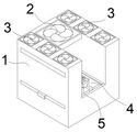
Fig. 1 is an appearance state diagram of the present invention.
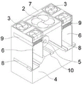
Fig. 2 is a schematic view of the half-section of the present invention.
Fig. 3 is a detailed schematic view of the slicing device of the present invention.
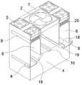
Fig. 4 is a schematic diagram of the half-section of the utility model.
In the figure: the device comprises a working machine body 1, a downward-pressing dust suppression fan 2, an upper dust suction and collection fan 3, a slicing working table 4, a slicing device 5, a dust collection cavity 6, a slicing working back plate 7, a dust collection drawer 8, a dust filter plate 9, a clamp sliding groove 10, a cutting motor 11, a cutting blade 12, a sliding back frame 13, a butt clamp 14, a clamp table 15, a sliding bottom frame 16, a pre-cutting groove 17, a drainage flow channel 18, a dust collection sliding groove 19 and a storage table 20.
Detailed Description
The invention will be described in further detail with reference to the accompanying drawings and specific embodiments.
The utility model provides a high-efficient section device of magnetic material, includes work organism 1, pushes down dust suppression fan 2, goes up suction dust collection fan 3, section workstation 4, section device 5, work organism 1 sets up the outside at section workstation 4, section device 5 sets up at work organism 1 inboard and section workstation 4 top surface, push down dust suppression fan 2 and set up at the interior top side of work organism 1, and push down dust suppression fan 2 and set up the top side at section workstation 4, go up suction dust collection fan 3 and be equipped with the multiunit, suction dust collection fan 3 is symmetrical setting in the top surface both sides of work organism 1 on the multiunit, and goes up suction dust collection fan 3 and sets up in the both sides that push down dust suppression fan 2.
The slicing machine is characterized in that the working machine body 1 comprises a dust collecting cavity 6 and a slicing working back plate 7, the dust collecting cavity 6 is symmetrically arranged in front of two sides of the slicing working back plate 7, the slicing working back plate 7 is arranged on the rear top surface of the slicing working table 4, the downward dust suppression fan 2 is fixed on the front side of the top end of the slicing working back plate 7, a dust collecting drawer 8 is arranged on the inner top side of the dust collecting cavity 6, a dust filtering plate 9 is arranged on the inner top side of the dust collecting cavity 6, the upward dust collection fan 3 is arranged on the top side of the dust collecting cavity 6, the dust filtering plate 9 is arranged on the bottom side of the upward dust collection fan 3, the rear side surface of the slicing device 5 is connected onto the slicing working back plate 7, the slicing device 5 can slide up and down on the front side surface of the slicing working back plate 7, a clamp sliding groove 10 is arranged on the top surface of the slicing working table 4, the bottom side surface of the slicing device 5 is connected into the clamp sliding groove 10, and the slicing device 5 can slide in the clamp sliding groove 10.
The slicing device 5 comprises a cutting motor 11, a cutting blade 12, a sliding back frame 13, a butt clamp 14, a clamp table 15 and a sliding bottom frame 16, the cutting motor 11 is fixed on the front side surface of the sliding back frame 13, the cutting blade 12 is connected on the bottom end side surface of the cutting motor 11, the butt clamp 14 is arranged on the clamp table 15, the sliding bottom frame 16 is arranged on the bottom surface of the clamp table 15, a pre-cutting groove 17 is formed in the clamp table 15, the cutting blade 12 is arranged on the top side of the pre-cutting groove 17, the sliding back frame 13 is connected on a slicing working back plate 7, and the sliding bottom frame 16 is connected in a clamp sliding groove 10 in the top surface of a slicing working table 4.
A drainage flow channel 18 is arranged between the dust collection cavity 6 and the slicing worktable 4, a dust collection chute 19 is formed in the bottom side of the dust collection cavity 6, the dust collection drawer 8 is arranged in the dust collection chute 19, the dust collection drawer 8 can slide in and out of the dust collection chute 19, an object placing table 20 is arranged on the side wall of the top end of the dust collection cavity 6, the dust filter plate 9 is arranged on the object placing table 20, and the dust filter plate 9 can slide in and out of the inner top side of the dust collection cavity 6.
The utility model discloses theory of operation: the use of this equipment, can embody by its characteristics, this equipment can gather and retrieve produced dust and particulate matter in the cutting process, the magnetic material who will wait to cut is placed on the butt clamp anchor clamps, remove the mobile position of section device in section work backplate and anchor clamps spout according to the cutting demand, cut into the thin slice through the cutting piece, the cutting process can produce magnetic particles and dust, if press down dust suppression fan work this moment, can blow particulate matter and dust to the section workstation, blow on the section workstation, prevent that the particulate matter from upwards splashing or spreading to the air in the cutting process, if last suction dust collection fan does not start, the dust can be pressed down dust suppression fan and blow the outside of equipment, just formed the diffusion, if start the suction dust collection fan, can form the negative pressure in the dust collection chamber, particulate matter and dust this moment are just inhaled the collection intracavity through the drainage runner, in the dust collection intracavity, less dust can be adsorbed in the dust filter plate bottom side, bigger particulate matter is then from the drainage runner inhales the direct dust collection that falls into in the collection chamber, the drawer can be changed after the dust collection slide, and can take out dust filter plate after the certain time.
The foregoing is a preferred embodiment of the present invention, and for those skilled in the art to understand the teaching of the present invention, the changes, modifications, replacements and variations to the embodiments will still fall within the protection scope of the present invention without departing from the principle and spirit of the present invention.
Claims (4)
1. The utility model provides a high-efficient section device of magnetic material, its characterized in that presses down dirt fan (2), goes up suction dust collection fan (3), section workstation (4), section device (5) including work organism (1), sets up in the outside of section workstation (4), section device (5) set up at work organism (1) inboard and section workstation (4) top surface, press down dirt fan (2) and set up in the interior top side of work organism (1), and press down dirt fan (2) and set up the top side at section workstation (4), go up suction dust collection fan (3) and be equipped with the multiunit, suction dust collection fan (3) are symmetrical setting in the top surface both sides of work organism (1) on the multiunit, and go up suction dust collection fan (3) and set up the both sides that press down dirt fan (2).
2. The efficient slicing device for the magnetic materials as claimed in claim 1, wherein the working machine body (1) is composed of a dust collecting cavity (6) and a slicing working back plate (7), the dust collecting cavity (6) is symmetrically arranged in front of two sides of the slicing working back plate (7), the slicing working back plate (7) is arranged on the rear top surface of the slicing working table (4), the downward-pressing dust suppression fan (2) is fixed on the front side of the top end of the slicing working back plate (7), a dust collection drawer (8) is arranged on the inner top side of the dust collecting cavity (6), a dust filter plate (9) is arranged on the inner top side of the dust collecting cavity (6), the upward-suction dust collection fan (3) is arranged on the top side of the dust collection cavity (6), the dust filter plate (9) is arranged on the bottom side of the upward-suction dust collection fan (3), the rear side surface of the slicing device (5) is connected to the slicing working back plate (7), the slicing device (5) can slide up and down on the front side surface of the slicing working back plate (7), the top surface of the slicing working table (4) is provided with a top surface, and a clamp (10) is connected to the bottom surface of the slicing device (5) and a sliding chute (10) which can slide in the slicing clamp (5) and can slide in the sliding groove (10) of the slicing working back plate (7).
3. The efficient slicing device for magnetic materials as claimed in claim 2, wherein the slicing device (5) is composed of a cutting motor (11), a cutting blade (12), a sliding back frame (13), a clamp (14), a clamp table (15) and a sliding bottom frame (16), the cutting motor (11) is fixed on the front side of the sliding back frame (13), the cutting blade (12) is connected on the bottom side of the cutting motor (11), the clamp (14) is arranged on the clamp table (15), the sliding bottom frame (16) is arranged on the bottom surface of the clamp table (15), a pre-cutting groove (17) is formed in the clamp table (15), the cutting blade (12) is arranged on the top side of the pre-cutting groove (17), the sliding back frame (13) is connected on the slicing back working plate (7), and the sliding bottom frame (16) is connected in the clamp sliding groove (10) on the top surface of the slicing working table (4).
4. The efficient slicing device for the magnetic materials as claimed in claim 2, wherein a drainage flow channel (18) is arranged between the dust collection chamber (6) and the slicing table (4), a dust collection chute (19) is formed in the bottom side of the dust collection chamber (6), the dust collection drawer (8) is arranged in the dust collection chute (19), the dust collection drawer (8) can slide inside and outside the dust collection chute (19), an object placing table (20) is arranged on the side wall of the top end of the dust collection chamber (6), the dust filter plate (9) is arranged on the object placing table (20), and the dust filter plate (9) can slide inside and outside the inner top side of the dust collection chamber (6).
Priority Applications (1)
| Application Number | Priority Date | Filing Date | Title |
|---|---|---|---|
| CN202220250200.2U CN217571142U (en) | 2022-02-07 | 2022-02-07 | High-efficient section device of magnetic material |
Applications Claiming Priority (1)
| Application Number | Priority Date | Filing Date | Title |
|---|---|---|---|
| CN202220250200.2U CN217571142U (en) | 2022-02-07 | 2022-02-07 | High-efficient section device of magnetic material |
Publications (1)
| Publication Number | Publication Date |
|---|---|
| CN217571142U true CN217571142U (en) | 2022-10-14 |
Family
ID=83536464
Family Applications (1)
| Application Number | Title | Priority Date | Filing Date |
|---|---|---|---|
| CN202220250200.2U Active CN217571142U (en) | 2022-02-07 | 2022-02-07 | High-efficient section device of magnetic material |
Country Status (1)
| Country | Link |
|---|---|
| CN (1) | CN217571142U (en) |
-
2022
- 2022-02-07 CN CN202220250200.2U patent/CN217571142U/en active Active
Similar Documents
| Publication | Publication Date | Title |
|---|---|---|
| EP3296048A1 (en) | Dust-reduced saw and method for realizing the same | |
| CN214184523U (en) | Shaving board processing is with inhaling bits edulcoration device | |
| CN217571142U (en) | High-efficient section device of magnetic material | |
| CN219188699U (en) | Automatic waste material cleaning and recycling device for valve body machining | |
| CN215614624U (en) | Precision mold with waste material collecting structure | |
| CN216503761U (en) | Processing milling machine waste recovery device | |
| CN214642694U (en) | Workpiece polishing device with waste collection function for machining | |
| CN214136443U (en) | Wood chip collecting device of wood carving machine | |
| CN212526286U (en) | Novel plate cutting machine | |
| CN114227541A (en) | Scrap collecting and processing device and method based on fan grinding | |
| CN213410536U (en) | Cutting device for machining with sweeps collect function | |
| CN216324804U (en) | Automatic reinforcing bar cutter of material loading | |
| CN213561390U (en) | Cutting device of mechanical workpiece | |
| CN219967273U (en) | Bedstead production cutting dust collector | |
| CN217225792U (en) | Cutting machine with garbage collection structure | |
| CN218194242U (en) | A burring equipment for steel sheet processing | |
| CN214768111U (en) | But height-adjusting's punching machine | |
| CN214721090U (en) | Sawing machine for machining rack of SC type construction elevator | |
| CN220409237U (en) | Effectual infrared ray stonecutter of dust fall | |
| CN218017373U (en) | Dust removal structure for engraving machine | |
| CN217621520U (en) | Concrete block cutting device | |
| CN220313600U (en) | Mobile dust collection device for wooden artware processing | |
| CN218461793U (en) | Furniture board burring device | |
| CN214772659U (en) | Cutting machine for wood working convenient to collect saw-dust | |
| CN208215711U (en) | A kind of portable pearl perforating device |
Legal Events
| Date | Code | Title | Description |
|---|---|---|---|
| GR01 | Patent grant | ||
| GR01 | Patent grant |