CN215614624U - Precision mold with waste material collecting structure - Google Patents
Precision mold with waste material collecting structure Download PDFInfo
- Publication number
- CN215614624U CN215614624U CN202122196286.3U CN202122196286U CN215614624U CN 215614624 U CN215614624 U CN 215614624U CN 202122196286 U CN202122196286 U CN 202122196286U CN 215614624 U CN215614624 U CN 215614624U
- Authority
- CN
- China
- Prior art keywords
- fixedly connected
- side wall
- base
- waste material
- waste
- Prior art date
- Legal status (The legal status is an assumption and is not a legal conclusion. Google has not performed a legal analysis and makes no representation as to the accuracy of the status listed.)
- Active
Links
Images


Landscapes
- Punching Or Piercing (AREA)
Abstract
The utility model belongs to the technical field of dies, and particularly relates to a precision die with a waste material collecting structure, which comprises a base, a workpiece table and a waste material collecting assembly, wherein the workpiece table is arranged on the base; the top of the base is fixedly connected with a group of supporting rods, and a cavity is formed in the base; the top of the supporting rod is fixedly connected with a top plate; a hydraulic cylinder is arranged at the bottom of the top plate; the workpiece table is fixedly connected to the top of the base, and a through hole is formed in the side wall of the workpiece table; an opening is formed in the inner side wall of the top end of the through hole, and a blanking port is formed at the bottom of the through hole; the waste material collecting assembly comprises a waste material box and a material sucking mechanism; the waste material box is arranged on the inner side wall of the bottom end of the cavity; the material sucking mechanism is arranged on the base; the waste material that gets off through the punching press is collected to absorb the waste material that splashes through inhaling material mechanism, make the work piece bench be difficult for remaining more waste material, avoid the trouble of artifical collection waste material.
Description
Technical Field
The utility model relates to the technical field of dies, in particular to a precise die with a waste material collecting structure.
Background
The stamping die is a die which can cause the workpiece to generate plastic deformation or separation by applying external force to the workpiece, the workpiece with required shape and size can be obtained by stamping, more workpiece waste materials can be remained on the working table surface when the workpiece is stamped, and the waste materials need to be collected to avoid influencing stamping.
Among the prior art at present, when accumulating more waste material on table surface, collect the arrangement through the staff to the waste material on the table surface, avoid the waste material to produce the influence to punching press work, but the manual work is collected the waste material comparatively troublesome, and work efficiency is low, consequently, proposes a precision mold with collect the waste material structure to above-mentioned problem.
SUMMERY OF THE UTILITY MODEL
In order to make up for the defects of the prior art and solve the problems that manual waste collection is troublesome and the working efficiency is low when workers collect and arrange waste on a working table, the utility model provides a precision die with a waste collection structure.
The technical scheme adopted by the utility model for solving the technical problems is as follows: the utility model relates to a precision die with a waste material collecting structure, which comprises a base, a workpiece table and a waste material collecting assembly, wherein the workpiece table is arranged on the base; the top of the base is fixedly connected with a group of supporting rods, and a cavity is formed in the base; the top of the supporting rod is fixedly connected with a top plate; a hydraulic cylinder is arranged at the bottom of the top plate; the output end of the hydraulic cylinder is provided with a punch; the workpiece table is fixedly connected to the top of the base, and a through hole is formed in the side wall of the workpiece table; an opening is formed in the inner side wall of the top end of the through hole, and a blanking port is formed at the bottom of the through hole; the blanking port is communicated with the inside of the cavity; the waste material collecting assembly is arranged on the base; the waste material collecting assembly comprises a waste material box and a material sucking mechanism; the waste material box is arranged on the inner side wall of the bottom end of the cavity; the material sucking mechanism is arranged on the base; the waste material that gets off through the punching press is collected to absorb the waste material that splashes through inhaling material mechanism, make the work piece bench be difficult for remaining more waste material, avoid the trouble of artifical collection waste material.
Preferably, the material suction mechanism comprises a waste bin, an air suction pump, a support and a dust hood; the waste bin is fixedly connected to the outer side wall of the base; the air pump is fixedly connected to the top of the base, the input end of the air pump is fixedly connected with an air inlet pipe, and the output end of the air pump is fixedly connected with an air outlet pipe; the bracket is fixedly connected on the outer side wall of the workpiece table; the dust hood is fixedly connected to the end part of the bracket; the air inlet pipe is communicated with the interior of the dust hood; the end part of the air outlet pipe extends into the waste bin and is communicated with the inside of the waste bin; the air pump is started, so that the waste materials are conveyed to the waste material box through the air inlet pipe and the air outlet pipe to be collected, and the splashed waste materials are collected.
Preferably, the top of the base is provided with a sliding chute; a clamping mechanism is arranged inside the sliding groove; the clamping mechanism comprises a clamping block, a threaded rod and a clamping plate; a groove is formed in the side wall of the clamping block; a threaded hole is formed in the inner side wall of the top end of the groove; the threaded rod is rotatably connected inside the threaded hole and is in threaded fit with the inner side wall of the threaded hole; the clamping plate is fixedly connected to the end part of the threaded rod; the workpiece penetrates through the through hole, one end of the workpiece is inserted into the groove, the threaded rod is rotated, and the clamping plate is gradually close to the workpiece and compresses the workpiece in the rotating process of the threaded rod, so that the stability of the workpiece is guaranteed.
Preferably, the top of the base is fixedly connected to the support plate; an electric push rod is fixedly connected to the side wall of the support plate; the output end of the electric push rod is fixedly connected with the side wall of the clamping block; the electric push rod is started, the clamping block is pushed to slide along the sliding groove through the electric push rod, and then the workpiece is fed along the through hole, and further the punch punches the workpiece for multiple times.
Preferably, the bottom of the clamping plate is fixedly connected with a rubber block; the inner side wall of the through hole is connected with a pair of limiting plates in a sliding manner through a spring; through set up the frictional force at splint bottom increase splint and work piece contact position for splint are better to compressing tightly of work piece the effect, guarantee the stability of work piece, and the limiting plate is spacing to the work piece, avoids the work piece to take place the skew.
Preferably, a filter screen is fixedly connected to the inner side wall of the waste bin; the filter screen is positioned at the bottom of the air outlet pipe; the dust hood is obliquely arranged; through set up the filter screen in the garbage bin and be arranged in filtering the sweeps powder from outlet duct tip discharge waste, and then make the sweeps of great granule separate with pulverous sweeps.
The utility model has the advantages that:
1. according to the utility model, when the punch performs stamping operation on a workpiece, stamped and dropped waste materials fall into the waste material box through the blanking port in the workpiece table, and when the stamping operation is performed, scraps of the waste materials can splash from the workpiece, the air suction pump is started, the splashed waste materials are driven by air flow to enter the dust hood, so that the waste materials are conveyed into the waste material box through the air inlet pipe and the air outlet pipe to be collected, the splashed waste materials are collected, the trouble of manually cleaning the waste materials is avoided, the waste materials are collected through the matching operation of the waste material box and the waste material box, and the trouble of manually collecting the waste materials is avoided;
2. according to the utility model, one end of a workpiece is inserted into the groove, the threaded rod is rotated, the threaded rod is in threaded fit with the inner side wall of the threaded hole, the clamping plate is gradually close to the workpiece and compresses the workpiece in the rotating process of the threaded rod, the stability of the workpiece is ensured, the clamping block is driven to slide along the sliding groove by starting the electric push rod, so that the workpiece is fed along the through hole, the punch is used for punching the workpiece for multiple times, and the punching efficiency is improved.
Drawings
In order to more clearly illustrate the embodiments of the present invention or the technical solutions in the prior art, the drawings used in the description of the embodiments or the prior art will be briefly described below, and it is obvious that the drawings in the following description are only some embodiments of the present invention, and for those skilled in the art, other drawings can be obtained according to these drawings without inventive exercise.
FIG. 1 is a front sectional view of a first embodiment;
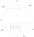
FIG. 2 is a side sectional view of the first embodiment;
FIG. 3 is an enlarged view of a portion of FIG. 1 at A;
FIG. 4 is an enlarged view of a portion of FIG. 2 at B;
FIG. 5 is a schematic three-dimensional structure diagram of a workbench and a limiting plate in the first embodiment;
fig. 6 is a front view of the second embodiment.
In the figure: 1. a base; 11. a support bar; 12. a cavity; 13. a top plate; 14. a hydraulic cylinder; 141. a punch; 15. a chute; 16. a support plate; 17. an electric push rod; 18. a non-slip mat; 2. a workpiece stage; 21. a through hole; 211. a limiting plate; 22. an opening; 23. a blanking port; 3. a waste collection assembly; 31. a waste material box; 32. A material sucking mechanism; 321. a waste bin; 322. an air pump; 323. a support; 324. a dust hood; 325. an air inlet pipe; 326. an air outlet pipe; 327. a filter screen; 4. a clamping mechanism; 41. a clamping block; 411. a groove; 412. a threaded hole; 42. a threaded rod; 43. a splint; 431. a rubber block.
Detailed Description
The technical solutions in the embodiments of the present invention will be clearly and completely described below with reference to the drawings in the embodiments of the present invention, and it is obvious that the described embodiments are only a part of the embodiments of the present invention, and not all of the embodiments. All other embodiments, which can be derived by a person skilled in the art from the embodiments given herein without making any creative effort, shall fall within the protection scope of the present invention.
Example one
Referring to fig. 1-5, a precision mold with a scrap collecting structure includes a base 1, a work stage 2, and a scrap collecting assembly 3; a group of support rods 11 are fixedly connected to the top of the base 1, and a cavity 12 is formed in the base 1; a top plate 13 is fixedly connected to the top of the support rod 11; a hydraulic cylinder 14 is arranged at the bottom of the top plate 13; the output end of the hydraulic cylinder 14 is provided with a punch 141; the workpiece table 2 is fixedly connected to the top of the base 1, and a through hole 21 is formed in the side wall of the workpiece table 2; an opening 22 is formed in the inner side wall of the top end of the through hole 21, and a blanking port 23 is formed in the bottom of the through hole 21; the blanking port 23 is communicated with the interior of the cavity 12; the waste collecting component 3 is arranged on the base 1; the waste material collecting component 3 comprises a waste material box 31 and a material sucking mechanism 32; the waste material box 31 is arranged on the inner side wall of the bottom end of the cavity 12; the material sucking mechanism 32 is arranged on the base 1; during operation, pass the through-hole 21 of work piece platform 2 with the work piece and steadily place on work piece platform 2, hydraulic cylinder 14 is started, drift 141 through the 14 output of hydraulic cylinder punches the work piece, the waste material that the punching press got off drops in waste material box 31 through blanking mouth 23 in work piece platform 2, punch 141 carries out the punching press during operation to the work piece, the piece of waste material that can splash from the work piece, absorb the waste material that splashes through inhaling material mechanism 32, avoid remaining more waste material on work piece platform 2, reduce the work load of artifical clean waste material.
The material suction mechanism 32 comprises a waste box 321, a suction pump 322, a bracket 323 and a dust hood 324; the waste bin 321 is fixedly connected to the outer side wall of the base 1; the air pump 322 is fixedly connected to the top of the base 1, the input end of the air pump 322 is fixedly connected with an air inlet pipe 325, and the output end of the air pump 322 is fixedly connected with an air outlet pipe 326; the bracket 323 is fixedly connected on the outer side wall of the workpiece table 2; the dust hood 324 is fixedly connected to the end part of the bracket 323; the air inlet pipe 325 is communicated with the interior of the dust hood 324; the end part of the air outlet pipe 326 extends into the waste box 321 and is communicated with the inside of the waste box 321; during operation, when collecting the waste material that splashes, start aspiration pump 322, the waste material that splashes is inside dust hood 324 of advancing under the drive of air current, intake pipe 325 and dust hood 324 intercommunication again, and then makes the waste material be carried to waste bin 321 through intake pipe 325 and outlet duct 326 and collect to the waste material that splashes is collected in the realization, avoids the trouble of artifical clean waste material.
The top of the base 1 is provided with a sliding chute 15; a clamping mechanism 4 is arranged inside the sliding groove 15; the clamping mechanism 4 comprises a clamping block 41, a threaded rod 42 and a clamping plate 43; a groove 411 is arranged on the side wall of the clamping block 41; a threaded hole 412 is formed in the inner side wall of the top end of the groove 411; the threaded rod 42 is rotatably connected inside the threaded hole 412 and is in threaded fit with the inner side wall of the threaded hole 412; the clamping plate 43 is fixedly connected with the end part of the threaded rod 42; when the punching machine works, a workpiece penetrates through the through hole 21, one end of the workpiece is inserted into the groove 411, the threaded rod 42 is rotated, the threaded rod 42 is in threaded fit with the inner side wall of the threaded hole 412, the clamping plate 43 is gradually close to the workpiece and compresses the workpiece in the rotating process of the threaded rod 42, the stability of the workpiece is guaranteed, and when the workpiece is punched, the clamping block 41 is pushed to slide in the sliding groove 15, so that the punch 141 performs punching work on the workpiece at multiple positions.
The top of the base 1 is fixedly connected with a support plate 16; an electric push rod 17 is fixedly connected to the side wall of the support plate 16; the output end of the electric push rod 17 is fixedly connected with the side wall of the clamping block 41; during operation, the electric push rod 17 is started, the output end of the electric push rod 17 is fixedly connected with the side wall of the clamping block 41, so that the clamping block 41 is pushed by the electric push rod 17 to slide along the sliding groove 15, the workpiece is fed along the through hole 21, and the punch 141 punches the workpiece for multiple times.
The bottom of the clamping plate 43 is fixedly connected with a rubber block 431; a pair of limiting plates 211 is connected to the inner side wall of the through hole 21 in a sliding manner through a spring; during operation, through set up the frictional force of rubber piece 431 increase splint 43 and work piece contact position in splint 43 bottom for splint 43 is better to compressing tightly of work piece the effect, guarantees the stability of work piece, carries on spacingly to the work piece through limiting plate 211, avoids the work piece to take place the skew, makes the precision of punching press higher.
A filter screen 327 is fixedly connected to the inner side wall of the waste box 321; the filter screen 327 is positioned at the bottom of the air outlet pipe 326; the dust hood 324 is arranged obliquely; in operation, the filter screen 327 is disposed in the waste box 321 for filtering the powder of the waste discharged from the end of the air outlet pipe 326, so as to separate the waste with larger particles from the powder of the waste.
Example two
Referring to fig. 6, in a first comparative example, as another embodiment of the present invention, a non-slip mat 18 is fixed to the bottom of the base 1; the anti-skid pad 18 is made of rubber; during operation, the friction force between the base 1 and the contact part of the placing surface is increased by arranging the anti-slip mat 18 at the bottom of the base 1, so that the placing of the base 1 is more stable, and the base 1 is not easy to slide.
The working principle is that a workpiece is stably placed on a workpiece table 2 after penetrating through a through hole 21 of the workpiece table 2, a limiting plate 211 on the inner side wall of the through hole 21 is contacted with the side wall of the workpiece under the action of spring force, the workpiece is limited by the limiting plate 211 to avoid the workpiece from deviating, one end of the workpiece is inserted into a groove 411, a threaded rod 42 is rotated, the threaded rod 42 is in threaded fit with the inner side wall of a threaded hole 412, a clamping plate 43 gradually approaches the workpiece and presses the workpiece in the rotating process of the threaded rod 42, the stability of the workpiece is ensured, the friction force of the contact part of the clamping plate 43 and the workpiece is increased by arranging a rubber block 431 at the bottom of the clamping plate 43, the pressing effect of the clamping plate 43 on the workpiece is better, when the workpiece is pressed, a hydraulic cylinder 14 is started, the workpiece is pressed by a punch 141, the waste materials dropped by punching fall into a waste material box 31 through a blanking port 23 in the workpiece table 2, when the punch 141 performs punching operation, scraps of waste materials can be splashed from a workpiece, the air suction pump 322 is started, the splashed waste materials are driven by air flow to enter the dust hood 324, the air inlet pipe 325 is communicated with the dust hood 324, so that the waste materials are conveyed into the waste box 321 through the air inlet pipe 325 and the air outlet pipe 326, the splashed waste materials are collected, the trouble of manually cleaning the waste materials is avoided, the waste materials are collected through the cooperation of the waste material box 31 and the waste box 321, the trouble of manually collecting the waste materials is avoided, the workpiece is fed along the through hole 21 by starting the electric push rod 17 to push the clamping block 41 to slide along the sliding groove 15, the punch 141 performs multiple punching operations on the workpiece, the filter screen 327 is arranged in the waste box 321 and is used for filtering waste powder in the waste materials discharged from the end part of the air outlet pipe 326, and the waste chips with larger particles are separated from the powdered waste chips, the friction force of the contact part of the base 1 and a placing surface is increased by arranging the anti-slip mat 18 at the bottom of the base 1, so that the base 1 is placed more stably.
In the description herein, references to the description of "one embodiment," "an example," "a specific example" or the like are intended to mean that a particular feature, structure, material, or characteristic described in connection with the embodiment or example is included in at least one embodiment or example of the utility model. In this specification, the schematic representations of the terms used above do not necessarily refer to the same embodiment or example. Furthermore, the particular features, structures, materials, or characteristics described may be combined in any suitable manner in any one or more embodiments or examples.
The foregoing shows and describes the general principles, essential features, and advantages of the utility model. It will be understood by those skilled in the art that the present invention is not limited to the embodiments described above, which are described in the specification and illustrated only to illustrate the principle of the present invention, but that various changes and modifications may be made therein without departing from the spirit and scope of the present invention, which fall within the scope of the utility model as claimed.
Claims (6)
1. The utility model provides a precision mold with collect waste material structure which characterized in that: comprises a base (1), a workpiece table (2) and a waste collecting component (3); the top of the base (1) is fixedly connected with a group of supporting rods (11), and a cavity (12) is arranged in the base (1); a top plate (13) is fixedly connected to the top of the supporting rod (11); a hydraulic cylinder (14) is arranged at the bottom of the top plate (13); the output end of the hydraulic cylinder (14) is provided with a punch (141); the workpiece table (2) is fixedly connected to the top of the base (1), and a through hole (21) is formed in the side wall of the workpiece table (2); an opening (22) is formed in the inner side wall of the top end of the through hole (21), and a blanking port (23) is formed in the bottom of the through hole (21); the blanking port (23) is communicated with the interior of the cavity (12); the waste collecting component (3) is arranged on the base (1); the waste material collecting assembly (3) comprises a waste material box (31) and a material sucking mechanism (32); the waste material box (31) is arranged on the inner side wall of the bottom end of the cavity (12); the material suction mechanism (32) is arranged on the base (1).
2. A precision mold having a scrap collecting structure in accordance with claim 1, wherein: the material suction mechanism (32) comprises a waste box (321), a suction pump (322), a support (323) and a dust hood (324); the waste box (321) is fixedly connected to the outer side wall of the base (1); the air suction pump (322) is fixedly connected to the top of the base (1), the input end of the air suction pump (322) is fixedly connected with an air inlet pipe (325), and the output end of the air suction pump is fixedly connected with an air outlet pipe (326); the bracket (323) is fixedly connected to the outer side wall of the workpiece table (2); the dust hood (324) is fixedly connected to the end part of the bracket (323); the air inlet pipe (325) is communicated with the interior of the dust hood (324); the end part of the air outlet pipe (326) extends into the waste box (321) and is communicated with the inside of the waste box (321).
3. A precision mold having a scrap collecting structure in accordance with claim 2, wherein: the top of the base (1) is provided with a sliding chute (15); a clamping mechanism (4) is arranged in the sliding groove (15); the clamping mechanism (4) comprises a clamping block (41), a threaded rod (42) and a clamping plate (43); a groove (411) is arranged on the side wall of the clamping block (41); a threaded hole (412) is formed in the inner side wall of the top end of the groove (411); the threaded rod (42) is rotatably connected inside the threaded hole (412) and is in threaded fit with the inner side wall of the threaded hole (412); the clamping plate (43) is fixedly connected to the end part of the threaded rod (42).
4. A precision mold having a scrap collecting structure in accordance with claim 3, wherein: the top of the base (1) is fixedly connected with a support plate (16); an electric push rod (17) is fixedly connected to the side wall of the support plate (16); the output end of the electric push rod (17) is fixedly connected with the side wall of the clamping block (41).
5. The precision mold with a scrap collecting structure in accordance with claim 4, wherein: the bottom of the clamping plate (43) is fixedly connected with a rubber block (431); a pair of limiting plates (211) are connected to the inner side wall of the through hole (21) in a sliding mode through springs.
6. The precision mold with a scrap collecting structure in accordance with claim 5, wherein: a filter screen (327) is fixedly connected to the inner side wall of the waste box (321); the filter screen (327) is positioned at the bottom of the air outlet pipe (326); the dust hood (324) is arranged obliquely.
Priority Applications (1)
| Application Number | Priority Date | Filing Date | Title |
|---|---|---|---|
| CN202122196286.3U CN215614624U (en) | 2021-09-10 | 2021-09-10 | Precision mold with waste material collecting structure |
Applications Claiming Priority (1)
| Application Number | Priority Date | Filing Date | Title |
|---|---|---|---|
| CN202122196286.3U CN215614624U (en) | 2021-09-10 | 2021-09-10 | Precision mold with waste material collecting structure |
Publications (1)
| Publication Number | Publication Date |
|---|---|
| CN215614624U true CN215614624U (en) | 2022-01-25 |
Family
ID=79914882
Family Applications (1)
| Application Number | Title | Priority Date | Filing Date |
|---|---|---|---|
| CN202122196286.3U Active CN215614624U (en) | 2021-09-10 | 2021-09-10 | Precision mold with waste material collecting structure |
Country Status (1)
| Country | Link |
|---|---|
| CN (1) | CN215614624U (en) |
Cited By (1)
| Publication number | Priority date | Publication date | Assignee | Title |
|---|---|---|---|---|
| CN115770809A (en) * | 2022-11-15 | 2023-03-10 | 明泰精密冲压(吴江)有限公司 | Automatic stamping equipment |
-
2021
- 2021-09-10 CN CN202122196286.3U patent/CN215614624U/en active Active
Cited By (1)
| Publication number | Priority date | Publication date | Assignee | Title |
|---|---|---|---|---|
| CN115770809A (en) * | 2022-11-15 | 2023-03-10 | 明泰精密冲压(吴江)有限公司 | Automatic stamping equipment |
Similar Documents
| Publication | Publication Date | Title |
|---|---|---|
| CN110355278B (en) | Metal stamping die | |
| CN215614624U (en) | Precision mold with waste material collecting structure | |
| CN104001777A (en) | Novel stamping device with dust collection function | |
| CN218192001U (en) | Flat iron punching and bending one-time forming die | |
| CN215094163U (en) | A perforating device for wood working | |
| CN111069789A (en) | Stabilize pole piece garbage collection equipment | |
| CN206446155U (en) | A kind of metal fillings collects briquetting forming machine automatically | |
| CN216138011U (en) | Automatic cover discharging mechanism of basic cover stamping equipment for easy-open covers | |
| CN218049858U (en) | Trimming die convenient to clearance waste material | |
| CN116020933A (en) | Automobile part stamping device and method with cleaning function | |
| CN212285503U (en) | Automobile sheet blanking die | |
| CN216324709U (en) | Garbage collection device for punch press | |
| CN212525588U (en) | Discharging device of large-size punching machine | |
| CN205416474U (en) | Rubbish compressing equipment extrusion die | |
| CN209349409U (en) | A kind of stamping die facilitating discharge waste material | |
| CN210210591U (en) | Corrugated container board cuts fixing device | |
| CN221537915U (en) | Collecting device of stamping die | |
| CN221515797U (en) | Punching device for sheet metal part machining | |
| CN211727265U (en) | Waste recovery device for punching machine for machine-building | |
| CN217571142U (en) | High-efficient section device of magnetic material | |
| CN212887277U (en) | Environment-friendly solid wood multilayer panel punches and uses fixing device | |
| CN215038508U (en) | Forming machine with dust removal function for refractory brick production | |
| CN213971576U (en) | Perforating device in paper processing production | |
| CN215467523U (en) | Machining die for outer threshold angle plate | |
| CN213496007U (en) | Hardware component mould blank convenient to open and close |
Legal Events
| Date | Code | Title | Description |
|---|---|---|---|
| GR01 | Patent grant | ||
| GR01 | Patent grant |