CN217251363U - Turnover case belt cleaning device - Google Patents
Turnover case belt cleaning device Download PDFInfo
- Publication number
- CN217251363U CN217251363U CN202122861325.7U CN202122861325U CN217251363U CN 217251363 U CN217251363 U CN 217251363U CN 202122861325 U CN202122861325 U CN 202122861325U CN 217251363 U CN217251363 U CN 217251363U
- Authority
- CN
- China
- Prior art keywords
- cleaning
- station
- turnover
- cleaning device
- case
- Prior art date
- Legal status (The legal status is an assumption and is not a legal conclusion. Google has not performed a legal analysis and makes no representation as to the accuracy of the status listed.)
- Active
Links
Images


Classifications
-
- Y—GENERAL TAGGING OF NEW TECHNOLOGICAL DEVELOPMENTS; GENERAL TAGGING OF CROSS-SECTIONAL TECHNOLOGIES SPANNING OVER SEVERAL SECTIONS OF THE IPC; TECHNICAL SUBJECTS COVERED BY FORMER USPC CROSS-REFERENCE ART COLLECTIONS [XRACs] AND DIGESTS
- Y02—TECHNOLOGIES OR APPLICATIONS FOR MITIGATION OR ADAPTATION AGAINST CLIMATE CHANGE
- Y02P—CLIMATE CHANGE MITIGATION TECHNOLOGIES IN THE PRODUCTION OR PROCESSING OF GOODS
- Y02P70/00—Climate change mitigation technologies in the production process for final industrial or consumer products
- Y02P70/50—Manufacturing or production processes characterised by the final manufactured product
Landscapes
- Cleaning In General (AREA)
Abstract
The utility model provides a turnover box cleaning device, which comprises a receiving station and a cleaning station; the receiving station comprises a station support, a first transfer chain, a first conveying motor and a turnover mechanism; the turnover mechanism is arranged on the station support and comprises a right-angle supporting plate and a turnover motor, the turnover motor drives the right-angle supporting plate to rotate by 90 degrees, the first transfer chains are arranged on the tracks on two sides of the station support, and the first conveying motor drives the first transfer chains to rotate through chain wheels arranged on two ends of the tracks; the cleaning station comprises a travelling mechanism, a cantilever, a cleaning frame, a driving assembly and a brush, the rear end of the cantilever is arranged on the travelling mechanism, the cleaning frame is arranged at the front end of the cantilever, the brush is arranged on the cleaning frame through the driving assembly, and the driving assembly drives the brush to move around the cleaning frame. The device has the advantages of high cleaning automation degree, labor saving and high cleaning efficiency.
Description
Technical Field
The utility model relates to a cleaning equipment of cigarette production link, specific theory has related to a turnover case belt cleaning device.
Background
The turnover box belongs to a common container on a tobacco production line, and after the turnover box is used, the turnover box needs to be cleaned and cleaned, so that the turnover box is wide in application and high in cleaning labor intensity.
For example, in the vacuum moisture regaining process of the tobacco processing line, tobacco leaves are unpacked and then are put into a vacuum moisture regaining turnover box, and then enter a vacuum moisture regaining machine from a conveying channel to be subjected to vacuum moisture regaining. The net wall of the turnover box can not be effectively cleaned for a long time, and the problems of uneven vacuum moisture regain, oil stain accumulation, tobacco pest breeding and the like are caused.
Because the volume and the weight of the vacuum dampening transfer box body are large, a proper cleaning machine is not available in the industry at present, the cleaning method in the industry of the domestic silk making workshop is still manually carried out, namely, the vacuum dampening transfer box is manually dragged out by a forklift and is manually cleaned by a high-pressure water gun, the method wastes time and labor, and the cleaning effect is not ideal.
After the tobacco leaves are subjected to vacuum moisture regain, the tobacco leaves with tobacco tar bonded on the box bottom and the box wall cannot be completely poured when the tobacco leaves are poured, and the tobacco leaves in the vacuum moisture regain turnover box cannot be completely removed even if the tobacco leaves are manually flushed by high-pressure gas.
Other types of totes also have similar problems.
In order to solve the above problems, people are always seeking an ideal technical solution.
SUMMERY OF THE UTILITY MODEL
The utility model aims at the not enough of prior art to a circulation case belt cleaning device that washing degree of automation is high, practice thrift the labour, clean efficient is provided.
In order to realize the purpose, the utility model discloses the technical scheme who adopts is: a turnover box cleaning device comprises a receiving station and a cleaning station;
the receiving station comprises a station support, a first transfer chain, a first conveying motor and a turnover mechanism;
the turnover mechanism is arranged on the station support and comprises a right-angle supporting plate and a turnover motor, the turnover motor drives the right-angle supporting plate to rotate by 90 degrees, the first transfer chains are arranged on the tracks on two sides of the station support, and the first conveying motor drives the first transfer chains to rotate through chain wheels arranged on two ends of the tracks;
the cleaning station comprises a traveling mechanism, a cantilever, a cleaning frame, a driving assembly and a brush, the rear end of the cantilever is installed on the traveling mechanism, the cleaning frame is installed at the front end of the cantilever, the brush is installed on the cleaning frame through the driving assembly, and the driving assembly drives the brush to move around the cleaning frame.
Basically, the driving assembly comprises a driving motor, a gear set, a plurality of transmission shafts arranged at the upper end and the lower end of the cleaning frame and a plurality of transmission chain wheels arranged on the transmission shafts, the transmission chain wheels which are opposite in upper and lower positions are driven by chains, and the hairbrushes are fixed on the transmission chains at equal intervals.
Basically, the wash rack is the rectangle frame, the brush is rectangular form brush, the brush hair of brush is in both ends position to both ends outside corner and extend to both ends.
Basically, the tail ends of the two flat plates forming the right-angle supporting plate are respectively provided with a position sensor.
Basically, the cleaning frame is provided with at least two rows of brushes side by side along the horizontal direction, and each group of chains is provided with at least two brushes along the circumferential direction.
Basically, running gear includes base, linear rail, rack, drive gear and walking motor, walking motor and drive gear install on the base, the both ends slidable mounting of base is on linear rail, walking motor drive gear rotates, drive gear and rack cooperation, drive base along linear rail walking.
Running gear includes base, linear rail, rack, drive gear and walking motor, walking motor and drive gear install on the base, the both ends slidable mounting of base is on linear rail, walking motor drive gear rotates, drive gear and rack cooperation, drive base along linear rail walking.
On the base, a plurality of high-pressure spray heads are arranged at the front end and the periphery of the cleaning frame.
Basically, center on it is provided with the washing case to wash the station, wash the case and surround and wash the station, wash the front end that the case corresponds the wash rack and leave the import, the front end that washs the case sets up flexible check curtain, flexible check curtain is in through the magnet actuation all around wash on the case.
Compared with the prior art, the utility model has substantive characteristics and progress, in particular to, the utility model can be directly applied to production lines needing turnover boxes, when the turnover boxes are used, the turnover boxes are transferred to a receiving station by using a forklift or a tool attached to the unloading turnover boxes, then the turnover boxes are turned over for 90 degrees by the turnover mechanism, the opening of the turnover boxes faces the front, the turnover boxes enter a cleaning box under the matching of a first transfer chain and a conveying roller group, then a brush is started to clean the interior of the turnover boxes, in the process, a walking mechanism on the cleaning station does reciprocating movement, the brush rotates along the chain simultaneously to clean the interior of the turnover boxes, and the left side wall and the right side wall of the turnover boxes are cleaned through bristles at two ends of the brush; when the turnover box needs to be cleaned, after cleaning work is finished, the high-pressure spray head is opened, high-temperature and high-pressure hot water is sprayed out, dirt on the inner side wall of the turnover box is removed under the assistance of the hairbrush, the dirt flows into the tobacco leaf collecting mechanism below, and then automatic cleaning and cleaning of the turnover box are achieved.
Drawings
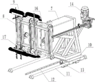
Fig. 1 is one of the overall structural schematic diagrams of the cleaning device for the transfer case of the present invention.
Fig. 2 is one of the overall structural schematic diagrams of the cleaning device for the transfer case of the present invention.
Fig. 3 is one of the schematic structural diagrams of the cleaning station of the present invention.
Fig. 4 is a second schematic structural view of the cleaning station of the present invention.
In the figure: 1. a station support; 2. a first transfer chain; 3. a first conveying motor; 4. a right-angle pallet; 5. turning over a motor; 6. a track; 7. a cantilever; 8. a cleaning rack; 9. a brush; 10. a base; 11. a linear track; 12. a rack; 13. a traveling motor; 14. a drive motor; 15. a gear set; 16. a drive shaft; 17. a drive sprocket; 18. a position sensor; 19. and (5) a turnover box.
Detailed Description
The technical solution of the present invention will be described in further detail through the following embodiments.
As shown in fig. 1-4, a cleaning device for a turnover box comprises a receiving station and a cleaning station;
the receiving station comprises a station support 1, a first transfer chain 2, a first conveying motor 3 and a turnover mechanism.
Turnover mechanism installs on station support 1, turnover mechanism includes right angle layer board 4 and upset motor 5, the drive of upset motor 5 right angle layer board 4 rotates 90, first transfer chain 2 is installed on the track 6 of 1 both sides of station support, first conveyor motor 3 drives first transfer chain 2 through installing the sprocket of installing at track 6 both ends and is rotary motion, constitutes a position sensor 18 is installed respectively to two dull and stereotyped ends of right angle layer board for whether the detection turnover case 19 blocks into the position, avoids the turnover in-process turnover case to turn over right angle layer board 4.
The cleaning station comprises a base 10, a linear track 11, a rack 12, a driving gear, a traveling motor 13, a cantilever 7, a cleaning rack 8, a driving component and a brush 9, the rear end of the cantilever 7 is installed on a traveling mechanism, the cleaning rack 8 is installed at the front end of the cantilever 7, the brush 9 is installed on the cleaning rack 8 through the driving component, the driving component drives the brush 9 to do circumferential motion around the cleaning rack 8, the traveling motor 13 drives the driving gear to rotate, the driving gear and the rack 12 are matched to drive the base 10 to do linear motion along the linear track 11, and the driving cantilever, the cleaning rack and the brush 9 are driven to do linear motion synchronously.
The driving assembly comprises a driving motor 14, a gear set 15, a plurality of transmission shafts 16 arranged at the upper end and the lower end of the cleaning frame 8 and a plurality of transmission chain wheels 17 arranged on the transmission shafts 16, the transmission chain wheels 17 which are opposite in the upper and lower positions are driven by chains, and the brushes are fixed on the transmission chains at equal intervals (only parts of the transmission chains are shown in the figure for illustration).
The cleaning frame 8 is a rectangular frame, the brush 9 is a strip-shaped brush, the bristles of the brush 9 are turned towards the outer sides of the two ends and extend to the two ends, and the purpose is that the cleaning work of the left side wall and the right side wall of the box body can be completed by using the brush.
At least two rows of hairbrushes are arranged on the cleaning rack side by side along the horizontal direction, and at least two hairbrushes are arranged on each group of chains along the circumferential direction.
The front end of wash rack and install a plurality of high pressure nozzle (not drawn in the picture) all around, center on the washing station is provided with washs the case, it surrounds the washing station to wash the case, wash the front end that the case corresponds the wash rack and leaves the import, the front end of wasing the case sets up flexible check curtain, flexible check curtain is in through the magnet actuation all around on the washing case.
The working principle is as follows:
the transfer device, such as a forklift, conveys the turnover box 8 to the turnover mechanism of the receiving station, automatically detects whether the turnover box 8 is put in place or not through the position sensor 7, after the safety is confirmed, the turnover mechanism rotates by 90 degrees, the turnover box is laid flat, the box opening is advanced, the first transfer chain is started to transfer the turnover box to the cleaning station, the conveying roller group 10 on the cleaning station receives the turnover box and drives the turnover box to move to the cleaning mechanism, then the walking mechanism drives the cantilever and the brush to walk into the turnover box, the driving motor is started, the brush cleans the interior of the turnover box, in the process, the walking mechanism drives the cantilever 7 and the cleaning frame 8 to move back and forth for a plurality of times so that the brush cleans the inner wall of the turnover box, dead corners are avoided, after the cleaning is finished, and conveying the turnover box to a receiving station in a reverse direction, reversing the turnover box through the turnover mechanism, and transferring the turnover box.
When cleaning is needed, after cleaning is finished, the high-pressure nozzle is opened, high-temperature and high-pressure water is sprayed out, and the interior of the turnover box is cleaned.
Finally, it should be noted that the above embodiments are only used for illustrating the technical solutions of the present invention and not for limiting the same; although the present invention has been described in detail with reference to preferred embodiments, it should be understood by those skilled in the art that: the invention can be modified or equivalent substituted for some technical features; without departing from the spirit of the present invention, it should be understood that the scope of the claims is intended to cover all such modifications and variations.
Claims (8)
1. The utility model provides a turnover case belt cleaning device which characterized in that: comprises a receiving station and a cleaning station;
the receiving station comprises a station support, a first transfer chain, a first conveying motor and a turnover mechanism;
the turnover mechanism is arranged on the station support and comprises a right-angle supporting plate and a turnover motor, the turnover motor drives the right-angle supporting plate to rotate 90 degrees, the first transfer chains are arranged on the rails on two sides of the station support, and the first conveying motor drives the first transfer chains to rotate through chain wheels arranged at two ends of the rails;
the cleaning station comprises a traveling mechanism, a cantilever, a cleaning frame, a driving assembly and a brush, the rear end of the cantilever is installed on the traveling mechanism, the cleaning frame is installed at the front end of the cantilever, the brush is installed on the cleaning frame through the driving assembly, and the driving assembly drives the brush to move around the cleaning frame.
2. The transfer case cleaning device according to claim 1, characterized in that: the driving assembly comprises a driving motor, a gear set, a plurality of transmission shafts arranged at the upper end and the lower end of the cleaning frame and a plurality of transmission chain wheels arranged on the transmission shafts, the transmission chain wheels which are opposite in upper and lower positions are driven by a chain, and the hairbrushes are fixed on the chain at equal intervals.
3. The transfer case cleaning device according to claim 2, characterized in that: the cleaning frame is a rectangular frame, the hairbrush is a strip-shaped hairbrush, and the bristles of the hairbrush are turned towards the outer sides of the two ends at the positions of the two ends and extend to the two ends.
4. The transfer case cleaning device according to claim 2, characterized in that: and the tail ends of the two flat plates forming the right-angle supporting plate are respectively provided with a position sensor.
5. The transfer case cleaning device according to claim 4, wherein: at least two rows of hairbrushes are arranged on the cleaning rack side by side along the horizontal direction, and at least two hairbrushes are arranged on each group of chains along the circumferential direction.
6. The transfer case cleaning device according to claim 5, wherein: running gear includes base, linear rail, rack, drive gear and walking motor, walking motor and drive gear install on the base, the both ends slidable mounting of base is on linear rail, walking motor drive gear rotates, drive gear and rack cooperation, drive base along linear rail walking.
7. The transfer case cleaning device according to any one of claims 1 to 6, wherein: and a plurality of high-pressure spray heads are arranged at the front end and the periphery of the cleaning frame.
8. The transfer case cleaning device according to claim 7, wherein: center on it is provided with the washing case to wash the station, wash the case and surround the washing station, the front end that washs the case and correspond the wash rack leaves the import, the front end that washs the case sets up flexible check apron, be in through the magnet actuation around the flexible check apron wash on the case.
Priority Applications (1)
| Application Number | Priority Date | Filing Date | Title |
|---|---|---|---|
| CN202122861325.7U CN217251363U (en) | 2021-11-19 | 2021-11-19 | Turnover case belt cleaning device |
Applications Claiming Priority (1)
| Application Number | Priority Date | Filing Date | Title |
|---|---|---|---|
| CN202122861325.7U CN217251363U (en) | 2021-11-19 | 2021-11-19 | Turnover case belt cleaning device |
Publications (1)
| Publication Number | Publication Date |
|---|---|
| CN217251363U true CN217251363U (en) | 2022-08-23 |
Family
ID=82881557
Family Applications (1)
| Application Number | Title | Priority Date | Filing Date |
|---|---|---|---|
| CN202122861325.7U Active CN217251363U (en) | 2021-11-19 | 2021-11-19 | Turnover case belt cleaning device |
Country Status (1)
| Country | Link |
|---|---|
| CN (1) | CN217251363U (en) |
-
2021
- 2021-11-19 CN CN202122861325.7U patent/CN217251363U/en active Active
Similar Documents
| Publication | Publication Date | Title |
|---|---|---|
| CN207805871U (en) | A kind of Furniture panel Full-automatic paint spraying production line | |
| CN201239103Y (en) | Machine for cleaning large carpet with broad width | |
| CN109967297A (en) | A kind of Furniture panel Full-automatic paint spraying production line | |
| CN101647682B (en) | Large-width carpet cleaning machine | |
| CN206911845U (en) | Multi-groove type hexagonal rotating cage supersonic wave cleaning machine | |
| CN104026710A (en) | Full-automatic cleaning system for edible mushroom and use method thereof | |
| CN204968918U (en) | Egg washs and air -dries integrated device | |
| CN210794774U (en) | Food conveyer belt with cleaning device | |
| CN112796266A (en) | Novel environmental protection dust collecting equipment | |
| CN109249903B (en) | Automatic cleaning device for high-speed train | |
| CN215940969U (en) | Automatic cleaning device for plug tray | |
| CN217251363U (en) | Turnover case belt cleaning device | |
| CN109201666A (en) | A kind of automatic cleaning equipment of vial | |
| CN219442148U (en) | Vacuum paint spraying device | |
| CN215918359U (en) | Moist cave dish self-cleaning device | |
| CN113909173B (en) | Automatic change brilliant support and remove gluey equipment | |
| CN209753510U (en) | Glass product cleaning device | |
| CN213727991U (en) | Digital product panel cleaning device | |
| CN210816616U (en) | Full-automatic glass bottle ash removal device | |
| CN209849198U (en) | Mould strip cleaning and spraying device | |
| CN206897931U (en) | Dedusting mechanism for spraying equipment | |
| CN216397446U (en) | Automatic oral liquid bottle washing equipment | |
| CN220363940U (en) | Wisdom commodity circulation transportation's goods transfer device | |
| CN106824874B (en) | Vertical glass cleaning device | |
| CN214782690U (en) | Conveying mechanism of clothes scrubbing machine |
Legal Events
| Date | Code | Title | Description |
|---|---|---|---|
| GR01 | Patent grant | ||
| GR01 | Patent grant |