CN217183936U - Beef cattle is raised and uses fodder reducing mechanism - Google Patents
Beef cattle is raised and uses fodder reducing mechanism Download PDFInfo
- Publication number
- CN217183936U CN217183936U CN202221024313.7U CN202221024313U CN217183936U CN 217183936 U CN217183936 U CN 217183936U CN 202221024313 U CN202221024313 U CN 202221024313U CN 217183936 U CN217183936 U CN 217183936U
- Authority
- CN
- China
- Prior art keywords
- box body
- fixedly connected
- rotating shaft
- feeding
- side wall
- Prior art date
- Legal status (The legal status is an assumption and is not a legal conclusion. Google has not performed a legal analysis and makes no representation as to the accuracy of the status listed.)
- Active
Links
Images


Classifications
-
- Y—GENERAL TAGGING OF NEW TECHNOLOGICAL DEVELOPMENTS; GENERAL TAGGING OF CROSS-SECTIONAL TECHNOLOGIES SPANNING OVER SEVERAL SECTIONS OF THE IPC; TECHNICAL SUBJECTS COVERED BY FORMER USPC CROSS-REFERENCE ART COLLECTIONS [XRACs] AND DIGESTS
- Y02—TECHNOLOGIES OR APPLICATIONS FOR MITIGATION OR ADAPTATION AGAINST CLIMATE CHANGE
- Y02P—CLIMATE CHANGE MITIGATION TECHNOLOGIES IN THE PRODUCTION OR PROCESSING OF GOODS
- Y02P60/00—Technologies relating to agriculture, livestock or agroalimentary industries
- Y02P60/80—Food processing, e.g. use of renewable energies or variable speed drives in handling, conveying or stacking
- Y02P60/87—Re-use of by-products of food processing for fodder production
Landscapes
- Apparatuses For Bulk Treatment Of Fruits And Vegetables And Apparatuses For Preparing Feeds (AREA)
Abstract
The utility model discloses a feed crushing device for beef cattle raising, which comprises a box body, a feeding mechanism and a reciprocating mechanism, wherein the box body is horizontally provided with a rotating shaft, the side wall of the rotating shaft in the box body is fixedly connected with a plurality of crushing knives, one end of the rotating shaft passes through the side wall of the box body and is fixedly connected with a motor, the upper end of the box body is provided with a second chute which is parallel to the rotating shaft, the utility model utilizes a connecting block and a moving block to connect a first feeding pipe and a second feeding pipe together, thereby leading the first feeding pipe and the second feeding pipe to move together, improving the efficiency of crushing and mixing forage grass and ingredients, leading the reciprocating screw rod to rotate through the rotating shaft, leading the second feeding pipe and the first feeding pipe to convey forage grass and ingredients along the axial direction of the rotating shaft, being convenient for the mixing forage grass and ingredients, meanwhile, the burden of crushing by the crushing knife is reduced, and the efficiency of crushing and mixing the forage grass and the ingredients is improved.
Description
Technical Field
The utility model relates to a technical field is smashed to the fodder, specifically is a beef cattle is raised and uses fodder reducing mechanism.
Background
When the beef cattle are raised, a large amount of forage grass is needed to feed the beef cattle, and the forage grass refers to herbaceous plants with stems and leaves capable of being used as forage for herbivores. The forage grass has strong regenerative power, can be harvested for many times in a year, and is rich in various trace elements and vitamins, so the forage grass becomes the first choice for raising livestock.
The publication No. CN216224725U is a crushing device for the alfalfa feed of dairy cows, which comprises a box body, wherein a first rotating rod is rotationally connected in the box body, and a crushing knife is fixedly connected to the first rotating rod; the automatic feeding device also comprises a batching box fixedly connected to the box body, wherein a plurality of groups of discharging grooves are formed in the batching box, and a feeding pipe is fixedly connected to the batching box; first motor, fixed connection is on the box, wherein, first motor output end fixedly connected with second bull stick, fixedly connected with scraper blade on the second bull stick, the scraper blade pastes with the inside bottom wall of batching box mutually.
Above-mentioned utility model when using, the forage grass passes through the filling tube and carries on to smashing the sword, because the position of filling tube output is fixed, can lead to the forage grass that is close to the filling tube in large quantity, keeps away from the forage grass of filling tube in small quantity, though the batching has carried out the homodisperse, still can lead to forage grass and batching to mix inhomogeneous, and forage grass piles up in same position, can increase the burden of smashing the sword, influences the crushing efficiency of forage grass.
In view of the above problems, an improved feed crushing apparatus for beef cattle raising is now devised.
SUMMERY OF THE UTILITY MODEL
The utility model aims at providing a beef cattle is raised and is used fodder reducing mechanism to solve the problem that proposes in the above-mentioned background art.
In order to achieve the above object, the utility model provides a following technical scheme:
the utility model provides a beef cattle is raised and uses fodder reducing mechanism, includes box, feed mechanism and reciprocating motion mechanism, the lower extreme fixedly connected with of box is used for discharging the discharging pipe of smashing the back fodder, the inside level of box is provided with the rotation axis, the both ends of rotation axis are all rotated and are connected on the lateral wall of box, fixedly connected with a plurality of is used for carrying out kibbling crushing sword to the fodder on the rotation axis lateral wall of box inside, the lateral wall fixedly connected with that the box was passed to one of them end of rotation axis is used for driving rotation axis pivoted motor, motor fixed mounting is on the lateral wall of box, the second spout that is parallel to each other with the rotation axis is seted up to the upper end of box.
Feed mechanism sets up on the box for carry forage grass and batching simultaneously along the axial of rotation axis, the mixing of the forage grass and batching of being convenient for reduces the kibbling burden of crushing sword simultaneously, improves the crushing efficiency of forage grass.
The reciprocating mechanism is arranged on the box body and used for horizontally reciprocating the feeding mechanism, so that forage grass and ingredients are simultaneously conveyed along the axial direction of the rotating shaft.
As a further aspect of the present invention: the feeding mechanism comprises a second feeding pipe, the second feeding pipe is vertically arranged inside a second sliding groove, the second feeding pipe is connected to the inner wall of the second sliding groove in a sliding mode, a hopper used for conveying ingredients to the second feeding pipe is fixedly connected to the upper end of the second feeding pipe, a moving block is fixedly connected to the side wall of the second feeding pipe between the hopper and the second sliding groove, and the lower end of the moving block is connected to the upper end of the box body in a sliding mode.
The side wall of the box body close to the moving block is horizontally provided with a first sliding groove, the first sliding groove is arranged above the rotating shaft, the inner wall of the first sliding groove is connected with a first feeding pipe used for conveying forage grass to the inside of the box body in a sliding mode, one end, far away from the first sliding groove, of the first feeding pipe is fixedly connected with a connecting block, one end, far away from the first feeding pipe, of the connecting block is fixedly connected to the side wall, far away from the second feeding pipe, of the moving block, and the output end of the first feeding pipe is located under the output end of the second feeding pipe.
As the utility model discloses further scheme again: the reciprocating mechanism comprises a reciprocating screw rod, a threaded hole is horizontally formed in the center of the moving block, the reciprocating screw rod is connected to the threaded hole in the center of the moving block through threads of the side wall in a rotating mode, mounting plates used for supporting the reciprocating screw rod are rotatably connected to the two ends of the reciprocating screw rod, the lower end of each mounting plate is fixedly connected to the upper end of the side wall of the box body, one end, away from the motor, of the reciprocating screw rod penetrates through a first belt wheel fixedly connected with the mounting plates, one end, away from the motor, of the rotating shaft penetrates through a second belt wheel fixedly connected with the side wall of the box body and used in cooperation with the first belt wheel, and belts are sleeved on the side walls of the second belt wheel and the first belt wheel.
As a further aspect of the present invention: the bottom fixedly connected with of box is convenient for the fodder after smashing to collect the water conservancy diversion piece on the discharging pipe.
As a further aspect of the present invention: the bottom of hopper fixedly connected with is convenient for the batching to carry the inside sloping block of second inlet tube.
As a further aspect of the present invention: fixedly connected with is used for improving the enhancement rib of first inlet pipe lateral wall structural strength on the lateral wall of first inlet pipe.
As a further aspect of the present invention: and the inner walls of the first sliding groove and the second sliding groove are fixedly connected with felt pads.
Compared with the prior art, the beneficial effects of the utility model are that:
1. the utility model discloses be provided with feed mechanism, utilize connecting block and movable block to link together first inlet pipe and second inlet pipe to make first inlet pipe and second inlet pipe can remove together, make first inlet pipe and second inlet pipe carry the rotation axis with forage grass and batching simultaneously on, improve the efficiency that forage grass and batching smash the mixture.
2. The utility model discloses be provided with reciprocating motion mechanism, at the second band pulley, under the transmission of belt and first band pulley, make reciprocating screw rotate through the rotation axis, reciprocating screw drives movable block reciprocating motion, the movable block drives second inlet pipe and first inlet pipe horizontal reciprocating motion to make second inlet pipe and first inlet pipe carry forage grass and batching along the axial of rotation axis, the mixture of forage grass and batching of being convenient for reduces the kibbling burden of crushing sword simultaneously, improve the efficiency that forage grass and batching smashed the mixture.
Drawings
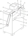
Fig. 1 is a front view of the three-dimensional structure of the present invention.
Fig. 2 is a schematic diagram of a rear three-dimensional structure of the present invention.
Fig. 3 is a schematic structural diagram of the present invention.
Wherein: 1-box body, 2-motor, 3-crushing cutter, 4-first feeding pipe, 5-mounting plate, 6-hopper, 7-moving block, 8-reciprocating screw, 9-second chute, 10-first belt wheel, 11-second feeding pipe, 12-first chute, 13-belt, 14-second belt wheel, 15-flow guide block, 16-discharging pipe, 17-rotating shaft and 18-connecting block.
Detailed Description
Referring to fig. 1-3, in an embodiment of the present invention, a feed crushing device for beef cattle raising includes a box 1, a feeding mechanism and a reciprocating mechanism, the lower end of the box body 1 is fixedly connected with a discharge pipe 16 for discharging the crushed feed, the bottom of the box body 1 is fixedly connected with a flow guide block 15 which is convenient for the crushed feed to be converged on the discharge pipe 16, a rotating shaft 17 is horizontally arranged in the box body 1, two ends of the rotating shaft 17 are rotatably connected to the side wall of the box body 1, a plurality of crushing knives 3 for crushing the feed are fixedly connected on the side wall of the rotating shaft 17 in the box body 1, one end of the rotating shaft 17 penetrates through the side wall of the box body 1 to be fixedly connected with a motor 2 for driving the rotating shaft 17 to rotate, the motor 2 is fixedly installed on the side wall of the box body 1, and a second sliding groove 9 parallel to the rotating shaft 17 is formed in the upper end of the box body 1.
Feed mechanism sets up on box 1 for carry forage grass and batching simultaneously along rotation axis 17's axial, the mixture of the forage grass and the batching of being convenient for reduces simultaneously and smashes 3 kibbling burdens of sword, improves the crushing efficiency of forage grass.
The reciprocating mechanism is arranged on the box body 1 and used for horizontally reciprocating the feeding mechanism, so that forage grass and ingredients are simultaneously conveyed along the axial direction of the rotating shaft 17.
Feed mechanism includes second inlet pipe 11, the vertical inside that sets up at second spout 9 of second inlet pipe 11, second inlet pipe 11 sliding connection is on the inner wall of second spout 9, the upper end fixedly connected with of second inlet pipe 11 is used for carrying the hopper 6 of batching to second inlet pipe 11, the bottom fixedly connected with of hopper 6 is convenient for the batching to carry the inside sloping block of second inlet pipe 11, fixedly connected with movable block 7 on the second inlet pipe 11 lateral wall between hopper 6 and the second spout 9, the lower extreme sliding connection of movable block 7 is in the upper end of box 1.
The side wall of the box body 1 close to the moving block 7 is horizontally provided with a first chute 12, the first chute 12 is arranged above the rotating shaft 17, the inner wall of the first chute 12 is connected with a first feed pipe 4 used for conveying forage to the inside of the box body 1 in a sliding mode, one end, far away from the first chute 12, of the first feed pipe 4 is fixedly connected with a connecting block 18, one end, far away from the first feed pipe 4, of the connecting block 18 is fixedly connected to the side wall, far away from the second feed pipe 11, of the moving block 7, and the output end of the first feed pipe 4 is located right below the output end of the second feed pipe 11.
The feeding mechanism is used for connecting the first feeding pipe 4 and the second feeding pipe 11 together by using the connecting block 18 and the moving block 7, so that the first feeding pipe 4 and the second feeding pipe 11 can move together, the first feeding pipe 4 and the second feeding pipe 11 simultaneously convey forage grass and ingredients to the rotating shaft 17, the efficiency of smashing and mixing the forage grass and the ingredients is improved, and the use by a user is facilitated.
The reciprocating mechanism comprises a reciprocating screw 8, a threaded hole is horizontally formed in the center of the moving block 7, the reciprocating screw 8 is rotatably connected to the threaded hole in the center of the moving block 7 through threads on the side wall, mounting plates 5 used for supporting the reciprocating screw 8 are rotatably connected to the two ends of the reciprocating screw 8, the lower ends of the mounting plates 5 are fixedly connected to the upper end of the side wall of the box body 1, one end, far away from the motor 2, of the reciprocating screw 8 penetrates through a first belt wheel 10 fixedly connected to the mounting plates 5, one end, far away from the motor 2, of the rotating shaft 17 penetrates through a second belt wheel 14 fixedly connected to the side wall of the box body 1 and matched with the first belt wheel 10, and a belt 13 is sleeved on the side walls of the second belt wheel 14 and the first belt wheel 10.
The reciprocating moving mechanism is used for driving the reciprocating screw 8 to rotate through the rotating shaft 17 under the transmission of the second belt wheel 14, the belt 13 and the first belt wheel 10, the reciprocating screw 8 drives the moving block 7 to reciprocate, and the moving block 7 drives the second feeding pipe 11 and the first feeding pipe 4 to horizontally reciprocate, so that the second feeding pipe 11 and the first feeding pipe 4 convey forage grass and ingredients along the axial direction of the rotating shaft 17, the forage grass and the ingredients are convenient to mix, the crushing burden of the crushing knife 3 is reduced, the efficiency of crushing and mixing the forage grass and the ingredients is improved, and the use by a user is convenient.
The utility model discloses a theory of operation is:
in use, fodder is fed through the first feed tube 4 into the interior of the housing 1 and ingredients are added to the interior of the hopper 6, the hopper 6 feeds ingredients to the interior of the second feed tube 11, and the second feed tube 11 feeds ingredients to the interior of the housing 1.
Simultaneously, the motor 2 is started, the output end of the motor 2 drives the rotating shaft 17 to rotate, the rotating shaft 17 drives the crushing cutter 3 to crush forage grass, the forage grass and ingredients are uniformly mixed, the rotating shaft 17 drives the second belt wheel 14 to rotate, the second belt wheel 14 drives the belt 13 to rotate, the belt 13 drives the first belt wheel 10 to rotate, the first belt wheel 10 drives the reciprocating screw 8 to rotate, under the action of threads, the reciprocating screw 8 drives the moving block 7 to horizontally reciprocate, the moving block 7 drives the second feeding pipe 11 and the connecting block 18 to move, the connecting block 18 drives the first feeding pipe 4 to move, so that the second feeding pipe 11 and the first feeding pipe 4 convey the forage grass and the ingredients to the crushing cutter 3 and the rotating shaft 17 along the axial direction of the rotating shaft 17, after crushing and stirring are completed, the flow guide block 15 collects the crushed forage to the discharging pipe 16, and the discharging pipe 16 discharges the forage.
Claims (7)
1. A feed crushing device for beef cattle raising, which comprises a box body (1), a feeding mechanism and a reciprocating mechanism, the lower end of the box body (1) is fixedly connected with a discharge pipe (16) for discharging the crushed feed, a rotating shaft (17) is horizontally arranged in the box body (1), two ends of the rotating shaft (17) are rotatably connected to the side wall of the box body (1), a plurality of crushing knives (3) for crushing the feed are fixedly connected on the side wall of the rotating shaft (17) in the box body (1), one end of the rotating shaft (17) penetrates through the side wall of the box body (1) and is fixedly connected with a motor (2) for driving the rotating shaft (17) to rotate, the motor (2) is fixedly arranged on the side wall of the box body (1), the device is characterized in that a second sliding groove (9) parallel to the rotating shaft (17) is formed in the upper end of the box body (1);
the feeding mechanism is arranged on the box body (1) and used for simultaneously conveying forage grass and ingredients along the axial direction of the rotating shaft (17);
the reciprocating mechanism is arranged on the box body (1) and used for horizontally reciprocating the feeding mechanism, so that forage grass and ingredients are simultaneously conveyed along the axial direction of the rotating shaft (17).
2. The beef cattle feeding feed crushing device as claimed in claim 1, wherein the feeding mechanism comprises a second feeding pipe (11), the second feeding pipe (11) is vertically arranged inside a second chute (9), the second feeding pipe (11) is slidably connected to the inner wall of the second chute (9), the upper end of the second feeding pipe (11) is fixedly connected with a hopper (6) used for conveying ingredients to the second feeding pipe (11), a moving block (7) is fixedly connected to the side wall of the second feeding pipe (11) between the hopper (6) and the second chute (9), and the lower end of the moving block (7) is slidably connected to the upper end of the box body (1);
first spout (12) have been seted up to the level on the lateral wall that box (1) is close to movable block (7), first spout (12) set up the top at rotation axis (17), sliding connection has first inlet pipe (4) that are used for carrying the forage grass to the inside of box (1) on the inner wall of first spout (12), the one end fixedly connected with connecting block (18) of first spout (12) are kept away from in first inlet pipe (4), the one end fixed connection that first inlet pipe (4) were kept away from in connecting block (18) is on the lateral wall that second inlet pipe (11) are kept away from in movable block (7), the output of first inlet pipe (4) is located second inlet pipe (11) output under.
3. The feed crushing device for beef cattle raising according to claim 2, wherein the reciprocating mechanism comprises a reciprocating screw (8), a threaded hole is horizontally formed in the center of the moving block (7), the reciprocating screw (8) is rotatably connected to the threaded hole in the center of the moving block (7) through threads on the side wall, mounting plates (5) for supporting the reciprocating screw (8) are rotatably connected to two ends of the reciprocating screw (8), the lower end of each mounting plate (5) is fixedly connected to the upper end of the side wall of the box body (1), one end of each reciprocating screw (8) far away from the motor (2) penetrates through the mounting plates (5) and is fixedly connected with a first belt wheel (10), one end of the rotating shaft (17) far away from the motor (2) penetrates through the side wall of the box body (1) and is fixedly connected with a second belt wheel (14) matched with the first belt wheel (10), the side walls of the second belt wheel (14) and the first belt wheel (10) are sleeved with a belt (13).
4. The feed grinder for beef cattle feeding as claimed in claim 1, wherein a deflector (15) is fixedly connected to the bottom of the housing (1) to facilitate the collection of the ground feed onto the discharge pipe (16).
5. A fodder crushing device for beef cattle feeding according to claim 2, characterized in that the bottom of the hopper (6) is fixedly connected with a sloping block for facilitating the feeding of ingredients to the inside of the second feeding pipe (11).
6. A fodder crushing device for beef cattle feeding as claimed in claim 2, characterized in that the side wall of the first feeding pipe (4) is fixedly connected with reinforcing ribs for improving the structural strength of the side wall of the first feeding pipe (4).
7. The feed grinder for feeding beef cattle as claimed in claim 2, wherein a felt pad is fixedly connected to each of the inner walls of the first chute (12) and the second chute (9).
Priority Applications (1)
| Application Number | Priority Date | Filing Date | Title |
|---|---|---|---|
| CN202221024313.7U CN217183936U (en) | 2022-04-30 | 2022-04-30 | Beef cattle is raised and uses fodder reducing mechanism |
Applications Claiming Priority (1)
| Application Number | Priority Date | Filing Date | Title |
|---|---|---|---|
| CN202221024313.7U CN217183936U (en) | 2022-04-30 | 2022-04-30 | Beef cattle is raised and uses fodder reducing mechanism |
Publications (1)
| Publication Number | Publication Date |
|---|---|
| CN217183936U true CN217183936U (en) | 2022-08-16 |
Family
ID=82775573
Family Applications (1)
| Application Number | Title | Priority Date | Filing Date |
|---|---|---|---|
| CN202221024313.7U Active CN217183936U (en) | 2022-04-30 | 2022-04-30 | Beef cattle is raised and uses fodder reducing mechanism |
Country Status (1)
| Country | Link |
|---|---|
| CN (1) | CN217183936U (en) |
-
2022
- 2022-04-30 CN CN202221024313.7U patent/CN217183936U/en active Active
Similar Documents
| Publication | Publication Date | Title |
|---|---|---|
| CN111821901A (en) | Additive mixing arrangement for fodder | |
| CN217183936U (en) | Beef cattle is raised and uses fodder reducing mechanism | |
| CN213376377U (en) | Feed additive grinds mixing arrangement | |
| CN219722518U (en) | Fodder proportioning machine of plant | |
| CN205385854U (en) | Mixed mixer of fodder grass | |
| CN207678368U (en) | A kind of straw cutting wire kneading machine | |
| CN216296148U (en) | Chinese herbal medicine composite mixing arrangement for beef cattle fodder | |
| CN214210124U (en) | A agitating unit for on full daily grain fodder preparation machine | |
| CN210869825U (en) | Total mixed ration fodder mixing machine | |
| CN209072967U (en) | One kind being used for the short crusher for fodder of sheep raising | |
| CN209155590U (en) | Forage expands mixing machine | |
| CN112369636A (en) | Poultry's feed processor | |
| CN218249958U (en) | Double-speed frequency conversion control daily ration machine | |
| CN216224725U (en) | Reducing mechanism is used to milk cow alfalfa fodder | |
| CN221230328U (en) | Forage grass processing mixing arrangement | |
| CN216059142U (en) | Compound feed stirring batch bin is bred to poultry | |
| CN210445635U (en) | Feed crushing mixer | |
| CN221059522U (en) | Fodder reducing mechanism | |
| CN214903001U (en) | Livestock breeding is with feed mixture device of throwing something and feeding | |
| CN215506599U (en) | Total mixed ration feed preparation machine | |
| CN220835934U (en) | Solid-liquid separation type crushing equipment | |
| CN214765788U (en) | Reducing mechanism of meat chicken feed production and processing usefulness | |
| CN220326299U (en) | Grass kneading machine for beef cattle cultivation | |
| CN109174348A (en) | Folium et Ramulus Mori microbiological fermented feed production system | |
| CN220432665U (en) | Fertilizer making machine utilizing cotton straw |
Legal Events
| Date | Code | Title | Description |
|---|---|---|---|
| GR01 | Patent grant | ||
| GR01 | Patent grant |