CN217141403U - Automatic cleaning device - Google Patents
Automatic cleaning device Download PDFInfo
- Publication number
- CN217141403U CN217141403U CN202123291982.9U CN202123291982U CN217141403U CN 217141403 U CN217141403 U CN 217141403U CN 202123291982 U CN202123291982 U CN 202123291982U CN 217141403 U CN217141403 U CN 217141403U
- Authority
- CN
- China
- Prior art keywords
- dust
- roller
- free cloth
- braking
- wiping
- Prior art date
- Legal status (The legal status is an assumption and is not a legal conclusion. Google has not performed a legal analysis and makes no representation as to the accuracy of the status listed.)
- Active
Links
Images

Landscapes
- Cleaning In General (AREA)
Abstract
The application discloses self-cleaning device for clean the product, include: a supply mechanism, a spraying mechanism, a braking mechanism, a wiping mechanism and a shifting mechanism. Above-mentioned automatic cleaning device through the cooperation between feed mechanism, spraying mechanism, arrestment mechanism, wiping mechanism and the mechanism of moving carries, has realized the automatic cleaning of product surface bad factor, has reduced the human cost. The spraying mechanism sprays cleaning liquid to the moving dustless cloth, the braking mechanism is matched with the supply mechanism to enable the dustless cloth to stop moving, and when the dustless cloth stops moving, the transfer mechanism is matched with the wiping mechanism to enable the profiling wiping head to wipe the surface of the product through the dustless cloth, so that bad factors on the surface of the product are cleaned, and the yield of the product after surface cleaning is improved.
Description
Technical Field
The application relates to the technical field of product cleaning, in particular to an automatic cleaning device.
Background
With the rapid development of the 3C product industry, people have higher and higher requirements on the appearance of products. After the existing product is produced in stages, the surface of the product has poor factors such as fog, fluff, particles, foreign matters and the like. Before the product is subjected to subsequent production such as film pasting, the adverse factors on the surface of the product need to be cleaned. At present, the method of manual cleaning is usually adopted to clean the adverse factors on the surface of the product. However, the manual cleaning effect is not good, the defective rate of the product surface after manual cleaning is high, and the required cleaning manpower is more, resulting in increased manpower cost.
SUMMERY OF THE UTILITY MODEL
In view of the above, there is a need for an automatic cleaning device to automatically clean the surface defect factors of the product, increase the yield of the product after surface cleaning, and reduce the labor cost.
The embodiment of the application provides an automatic cleaning device for clean the product, include: the feeding mechanism comprises a feeding driving part and a conveying roller assembly used for conveying the dust-free cloth, wherein the feeding driving part is connected with the conveying roller assembly and is used for driving the conveying roller assembly to rotate so that the conveying roller assembly drives the dust-free cloth to move; the spraying mechanism comprises a spraying head, the spraying head is arranged corresponding to a moving area of the dust-free cloth, and the spraying head is used for spraying cleaning liquid to the moving dust-free cloth; the braking mechanism comprises a braking driving part and a braking part connected with the braking driving part, the braking driving part is used for driving the braking part to be close to the dust-free cloth so as to press the dust-free cloth, and the braking driving part is matched with the supply driving part so as to stop the movement of the dust-free cloth; the wiping mechanism comprises a profiling wiping head, and the profiling wiping head is arranged corresponding to a moving area of the dust-free cloth; and the transfer mechanism comprises a manipulator, and the manipulator is used for transferring the product so as to be matched with the profiling wiping head to clean the product when the dust-free cloth stops moving.
In some embodiments, the feeding mechanism further comprises a drum around which the dust-free cloth is wound and can rotate; the conveying roller assembly comprises a first roller, a second roller, a third roller, a fourth roller and a fifth roller; the first roller is connected with the feeding driving piece and is opposite to the second roller; the first roller, the third roller, the fourth roller and the fifth roller are arranged at intervals along the moving direction of the dust-free cloth; and the dust-free cloth sequentially passes through the fifth roller, the fourth roller and the third roller and then enters between the first roller and the second roller.
In some embodiments, the braking mechanism further comprises a support; the supporting piece and the braking piece are respectively arranged on two opposite sides of a region where the dust-free cloth moves; the braking driving part drives the braking part to be close to or far away from the supporting part so as to press or loosen the dust-free cloth.
In some embodiments, the braking mechanism further comprises an elastic member connected with the braking member and away from the braking driving member, and the elastic member is used for elastically contacting the dust-free cloth.
In some embodiments, the braking driving member, the braking member, the elastic member and the supporting member form a pair of clamping assemblies, and the pair of clamping assemblies are arranged at intervals along the moving direction of the dust-free cloth; wherein the wiping mechanism is located between a pair of the clamping assemblies.
In some embodiments, the wiping mechanism further comprises a wiping drive coupled to the contoured wiping head for driving the contoured wiping head toward or away from the dust free cloth.
In some embodiments, the automatic cleaning device further comprises a detection mechanism, wherein the detection mechanism comprises a detector, and the detector is arranged corresponding to the moving area of the dust-free cloth and is used for detecting the dust-free cloth.
In some embodiments, the transfer mechanism further comprises a suction assembly comprising: an adsorption substrate connected to the robot; locate adsorb the base plate homonymy a plurality of absorption pieces and a plurality of backstop parts, a plurality of absorption pieces are used for adsorbing the product, a plurality of absorption pieces for adsorb the base plate protrusion in a plurality of backstop parts.
In some embodiments, the automatic cleaning device further comprises a dust suction mechanism, which is arranged adjacent to the transferring mechanism and is used for sucking the foreign matters on the products.
In some embodiments, the automated cleaning apparatus further comprises a seasoning mechanism disposed adjacent to the transfer mechanism for drying the product.
Above-mentioned automatic cleaning device through the cooperation between feed mechanism, spraying mechanism, arrestment mechanism, wiping mechanism and the mechanism of moving carries, has realized the automatic cleaning of product surface bad factor, has reduced the human cost. The spraying mechanism sprays cleaning liquid to the moving dustless cloth, the braking mechanism is matched with the supply mechanism to enable the dustless cloth to stop moving, and when the dustless cloth stops moving, the transfer mechanism is matched with the wiping mechanism to enable the profiling wiping head to wipe the surface of the product through the dustless cloth, so that bad factors on the surface of the product are cleaned, and the yield of the product after surface cleaning is improved.
Drawings
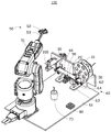
Fig. 1 is a schematic perspective view of an automatic cleaning device according to some embodiments of the present disclosure.
Fig. 2 is a schematic perspective view of the supply mechanism, the spray mechanism, the brake mechanism, the wiping mechanism, the detection mechanism, the bracket, the connection plate, and the first reinforcing member shown in fig. 1.
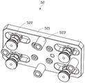
Fig. 3 is a schematic perspective view of the adsorption assembly shown in fig. 1.
Description of the main elements
Clamping assembly 31
Brake actuator 311
Retaining member 312
Support 313
Elastic member 314
Brake attachment 315
Second stiffener 316
First profiled wiping head 41
Second contoured wiper head 42
Wiping drive 43
Wiping attachment 44
Adsorbing member 522
Stop 523
Connecting rod 53
Machine table 60
Supporting substrate 61
Connecting plate 63
Detection connector 92
Dust-free cloth 200
Detailed Description
Reference will now be made in detail to embodiments of the present application, examples of which are illustrated in the accompanying drawings, wherein like or similar reference numerals refer to the same or similar elements or elements having the same or similar function throughout. The embodiments described below with reference to the accompanying drawings are illustrative and are only for the purpose of explaining the present application and are not to be construed as limiting the present application.
In the description of the present application, it is to be understood that the terms "center," "longitudinal," "lateral," "length," "width," "thickness," "upper," "lower," "front," "rear," "left," "right," "vertical," "horizontal," "top," "bottom," "inner," "outer," "clockwise," "counterclockwise," and the like are used in the orientations and positional relationships indicated in the drawings for convenience in describing the present application and for simplicity in description, and are not intended to indicate or imply that the referenced devices or elements must have a particular orientation, be constructed in a particular orientation, and be operated in a particular manner, and are not to be construed as limiting the present application. Furthermore, the terms "first", "second" and "first" are used for descriptive purposes only and are not to be construed as indicating or implying relative importance or implicitly indicating the number of technical features indicated. Thus, features defined as "first", "second", may explicitly or implicitly include one or more of the described features. In the description of the present application, it is to be noted that the meaning of "a plurality" is two or more unless specifically defined otherwise.
In the description of the present application, it is to be noted that, unless otherwise explicitly specified or limited, the terms "mounted," "connected," and "connected" are to be construed broadly, e.g., as meaning either a fixed connection, a removable connection, or an integral connection; they may be mechanically coupled, electrically coupled, or in communication with each other, directly coupled, or indirectly coupled through intervening media, in which case they may be interconnected, or in which case they may be in an interconnecting relationship. The specific meaning of the above terms in the present application can be understood by those of ordinary skill in the art as appropriate.
In this application, unless expressly stated or limited otherwise, the first feature "on" or "under" the second feature may comprise direct contact between the first and second features, or may comprise direct contact between the first and second features through another feature in between. Also, the first feature "on," "above" and "over" the second feature includes the first feature being directly above and obliquely above the second feature, or merely indicating that the horizontal thickness of the first feature is higher than that of the second feature. A first feature "under," "below," and "beneath" a second feature includes a first feature that is directly under and obliquely below the second feature, or simply means that the first feature is less horizontally thick than the second feature.
The following disclosure provides many different embodiments or examples for implementing different features of the application. In order to simplify the disclosure of the present application, specific example components and arrangements are described below. Of course, they are merely examples and are not intended to limit the present application. Moreover, the present application may repeat reference numerals and/or letters in the various examples, such repetition is for the purpose of simplicity and clarity and does not in itself dictate a relationship between the various embodiments and/or configurations discussed.
The embodiment of the application provides an automatic cleaning device for clean the product, include: the feeding mechanism comprises a feeding driving part and a conveying roller assembly used for conveying the dust-free cloth, wherein the feeding driving part is connected with the conveying roller assembly and is used for driving the conveying roller assembly to rotate so as to enable the conveying roller assembly to drive the dust-free cloth to move; the spraying mechanism comprises a spraying head, the spraying head is arranged corresponding to the area where the dust-free cloth moves, and the spraying head is used for spraying cleaning liquid to the moving dust-free cloth; the braking mechanism comprises a braking driving part and a braking part connected with the braking driving part, wherein the braking driving part is used for driving the braking part to be close to the dust-free cloth so as to press the dust-free cloth, and is matched with the supply driving part so as to stop the movement of the dust-free cloth; the wiping mechanism comprises a profiling wiping head, and the profiling wiping head is arranged corresponding to the moving area of the dust-free cloth; and the transfer mechanism comprises a mechanical arm, and the mechanical arm is used for transferring the product so as to be matched with the profiling wiping head to clean the product when the dust-free cloth stops moving.
The automatic cleaning device provided by the embodiment of the application realizes the automatic cleaning of the bad factors on the surface of the product and reduces the labor cost through the matching of the supply mechanism, the spraying mechanism, the braking mechanism, the wiping mechanism and the transfer mechanism. The spraying mechanism sprays cleaning liquid to the moving dustless cloth, the braking mechanism is matched with the supply mechanism to enable the dustless cloth to stop moving, and when the dustless cloth stops moving, the transfer mechanism is matched with the wiping mechanism to enable the profiling wiping head to wipe the surface of the product through the dustless cloth, so that bad factors on the surface of the product are cleaned, and the yield of the product after surface cleaning is improved.
Some embodiments of the present application will be described in detail below with reference to the accompanying drawings.
Referring to fig. 1, some embodiments of the present application provide an automatic cleaning apparatus 100. The automatic cleaning apparatus 100 is used to clean a product (not shown). The product can be the screen of electronic equipment, backplate, camera or other spare parts that need carry out the cleanness, and the product still can be the equipment that needs to carry out the cleanness such as tool, and this application embodiment does not limit this. The automatic cleaning apparatus 100 includes a supply mechanism 10, a spray mechanism 20, a brake mechanism 30, a wiping mechanism 40, and a transfer mechanism 50.
Referring to fig. 2, the feeding mechanism 10 includes a feeding driving member 11 and a conveying roller assembly 12 for conveying the dust-free cloth 200, the feeding driving member 11 is connected to the conveying roller assembly 12 and is used for driving the conveying roller assembly 12 to rotate, so that the conveying roller assembly 12 can move the dust-free cloth 200. The spraying mechanism 20 includes a spraying head 21, the spraying head 21 can be connected to a cleaning liquid supply device (not shown) provided on or external to the automatic cleaning device 100, the spraying head 21 is disposed corresponding to the area where the dust-free cloth 200 moves, and the spraying head 21 is used for spraying cleaning liquid to the moving dust-free cloth 200 to improve the cleaning effect of the dust-free cloth 200. The braking mechanism 30 includes a braking driving member 311 and a braking member 312 connected to the braking driving member 311, the braking driving member 311 is used for driving the braking member 312 to be close to the dust-free cloth 200 so that the braking member 312 presses the dust-free cloth 200, and cooperates with the feeding driving member 11 to stop the feeding driving member 11 from driving the conveying roller assembly 12 to rotate, so as to stop the dust-free cloth 200 from moving. The wiping mechanism 40 includes a profiling wiping head adapted to the product, which is disposed corresponding to an area where the dust-free cloth 200 moves, wherein the dust-free cloth 200 corresponding to the profiling wiping head is sprayed with the cleaning liquid by the spray head 21. The transfer mechanism 50 includes a robot 51, and the robot 51 transfers the product so as to cooperate with the copying wiping head to clean the product when the movement of the dust-free cloth 200 is stopped.
Some embodiments provide an implementation of the automatic cleaning device 100 that is substantially: the description will be given by taking a product as a camera of an electronic device as an example. First, the feed driving member 11 drives the conveying roller assembly 12 to rotate, so that the conveying roller assembly 12 moves the dust-free cloth 200. Then, the spray head 21 sprays cleaning liquid to the moving dust-free cloth 200. Then, when the dust-free cloth 200 sprayed with the cleaning liquid moves to a position corresponding to the profiling wiping head, the braking driving member 311 drives the braking member 312 to press the dust-free cloth 200, and the supply driving member 11 stops driving the transfer roller assembly 12 to rotate, so that the movement of the dust-free cloth 200 stops, and the dust-free cloth 200 is substantially tensioned under the cooperation of the supply mechanism 10 and the braking mechanism 30. Next, the transfer mechanism 50 transfers the product to the side of the dust-free cloth 200 away from the copying wiping head. Then, the transfer mechanism 50 drives the product to perform profiling movement and, in cooperation with the profiling wiping head, the dust-free cloth 200 sprayed with the cleaning liquid wipes the product until the wiping is completed. Next, the transfer mechanism 50 transfers the product to perform blanking and transfers a new product to be cleaned. Then, the brake driving member 311 drives the braking member 312 away from the dust-free cloth 200 to release the dust-free cloth 200, and the feed driving member 11 drives the transfer roller assembly 12 to rotate so that the movement of the dust-free cloth 200 is resumed. The cleaning device is reciprocating, so that the automatic cleaning of the bad factors on the surface of the product is realized, the influence of human factors on the cleaning effect is avoided, the labor cost is reduced, and the yield of the product after the surface is cleaned is improved.
In some embodiments, the cleaning solution may be alcohol, a surfactant solution, or other cleaning-available liquid.
Referring to fig. 1, in some embodiments, the automatic cleaning apparatus 100 further includes a machine table 60. The machine table 60 is used for carrying the supply mechanism 10, the spraying mechanism 20, the braking mechanism 30, the wiping mechanism 40, the transferring mechanism 50 and other mechanisms. In this way, the automatic cleaning device 100 achieves the effect of device integration, and the automatic cleaning device 100 is convenient to move and is also convenient to cooperate with other mechanisms or devices to achieve other functions of the product besides the automatic cleaning function, for example, the film pasting operation is performed after the product is cleaned.
In some embodiments, the machine table 60 includes a supporting substrate 61, a bracket 62, a connecting plate 63, and a first stiffener 64. The supporting base plate 61, the support 62, the connecting plates 63 and the first reinforcing members 64 are substantially plate-shaped, the support 62 is vertically connected with the supporting base plate 61 through the pair of connecting plates 63, the number of the first reinforcing members 64 is two, the two first reinforcing members 64 are respectively connected with the support 62 and the corresponding connecting plates 63, and the structural stability of the machine table 60 can be improved through the first reinforcing members 64. The transfer mechanism 50 may be provided on the support substrate 61. The supply mechanism 10, the spray mechanism 20, the brake mechanism 30, and the wiping mechanism 40 may be provided on the bracket 62.
It is understood that in other embodiments, the supply mechanism 10, the spraying mechanism 20, the braking mechanism 30 and the wiping mechanism 40 may be partially disposed on the support substrate 61, and another portion may be disposed on the support frame 62. The number of the connecting plates 63 and the first reinforcing members 64 may also be one, three, or more. When the bracket 62 is connected to the support base 61 by other means such as welding, the connection plate 63 and the first reinforcing member 64 may also be omitted.
In some embodiments, the robotic cleaning device 100 further comprises a suction mechanism 70. The dust suction mechanism 70 is disposed adjacent to the transfer mechanism 50 and may be disposed on the support substrate 61, and the dust suction mechanism 70 is configured to suck foreign matters such as lint and particles on the product that can be sucked. The dust suction mechanism 70 may suck foreign substances on the product by means of vacuum suction. Therefore, after the product is cleaned by wiping of the wiping mechanism 40, the dust suction mechanism 70 can further suck the foreign matters on the product, which is beneficial to improving the cleaning effect of the bad factors on the surface of the product.
It is understood that in other embodiments, the suction mechanism 70 may be disposed on the bracket 62.
In some embodiments, the automated cleaning device 100 further comprises a seasoning mechanism 80. The air drying mechanism 80 is adjacent to the transfer mechanism 50 and can be arranged on the support substrate 61 and adjacent to the dust suction mechanism 70, and the air drying mechanism 80 is used for blowing hot air or cold air to the product to dry the cleaning solution on the product and also can blow off foreign matters such as wool fibers and particles on the product which can be blown off. For example, the seasoning mechanism 80 blows plasma wind to the product to season the product and blow off foreign substances. So, the product through wiping mechanism 40 clean the back of wiping, again through air-dry mechanism 80 air-dry the cleaning solution on the product and blow off the foreign matter on the product, be favorable to promoting the clean effect of product surface harmful factor.
It is understood that in other embodiments, the airing mechanism 80 can also be disposed on the rack 62.
It is to be understood that in other embodiments, after the product is wiped by the wiping mechanism 40, the product may be deep cleaned by the airing mechanism 80 and the suction mechanism 70, or by the airing mechanism 80 or the suction mechanism 70. When the product is deeply cleaned by the airing mechanism 80 and the dust suction mechanism 70, the cleaning sequence of the airing mechanism 80 and the dust suction mechanism 70 can be changed.
With continued reference to fig. 2, in some embodiments, the feeding mechanism 10 further includes a roller 13, and the roller 13 is rotatably disposed on the bracket 62. The dust-free cloth 200 is wound around the drum 13 and can rotate along with the drum 13. Here, the area where the dust-free cloth 200 moves may be understood as a path or route where the dust-free cloth 200, which is separated from the drum 13, moves.
The transfer roller assembly 12 includes a first roller 121, a second roller 122, a third roller 123, a fourth roller 124, a fifth roller 125, a first piece 126, and a second piece 127. The first member 126 and the second member 127 are both substantially "door" shaped and are disposed on the bracket 62, the first roller 121 and the second roller 122 are rotatably disposed on the first member 126 and the second member 127, respectively, and illustratively, the first roller 121 and the second roller 122 are disposed on the first member 126 and the second member 127, respectively, through bearings. The first roller 121 is further connected to the supply driving member 11 and is disposed opposite to the second roller 122, and the first roller 121 and the second roller 122 may be in a meshing connection or other transmission connection, as long as they can rotate together to drive the dust-free cloth 200 to move. The supply driving member 11 and the first roller 121 are respectively disposed on two opposite side surfaces of the bracket 62, and the supply driving member 11 may be a servo motor. The first member 126, the second member 127 and the bearing are implemented as one way of arranging the first roller 121 and the second roller 122 opposite to each other, but may be implemented by other ways, such as an i-shaped bracket. Thus, when the supply driving member 11 drives the first roller 121 to rotate, the first roller 121 can drive the second roller 122 to rotate, and the first roller 121 and the second roller 122 drive the dust-free cloth 200 to move.
The first roller 121, the third roller 123, the fourth roller 124 and the fifth roller 125 are arranged at intervals along the moving direction of the dust-free cloth 200, the first roller 121, the third roller 123 and the fourth roller 124 are positioned below the dust-free cloth 200, the second roller 122 and the fifth roller 125 are positioned above the dust-free cloth 200, and the dust-free cloth 200 passes through the drum 13 and then sequentially passes through the fifth roller 125, the fourth roller 124 and the third roller 123 to enter between the first roller 121 and the second roller 122.
Some embodiments provide for an implementation of the supply mechanism 10 that is substantially: first, the drum 13 on which the dust-free cloth 200 is wound is rotatably provided on the bracket 62. Then, the dust-free cloth 200 is sequentially passed through the fifth roller 125, the fourth roller 124, and the third roller 123 using a mechanical device or a human, and finally passed through between the first roller 121 and the second roller 122. Then, the supply driving member 11 is started, so that the supply driving member 11 drives the first roller 121 to rotate, the first roller 121 drives the second roller 122 to rotate, and the dust-free cloth 200 moves, and the dust-free cloth 200 further drives the drum 13 to rotate under the driving of the first roller 121 and the second roller 122. In this way, the dust-free cloth 200 is continuously supplied.
It is understood that in other embodiments, the first roller 121, the third roller 123, and the fourth roller 124 may be positioned above the dust-free cloth 200, and the second roller 122 and the fifth roller 125 may be positioned below the dust-free cloth 200. Alternatively, the first roller 121, the third roller 123, and the fifth roller 125 may be positioned above the dust-free cloth 200, and the second roller 122 and the fourth roller 124 may be positioned below the dust-free cloth 200. The first roller 121, the second roller 122, the third roller 123, the fourth roller 124, and the fifth roller 125 may be arranged in other arrangements.
It will be appreciated that in other embodiments, the supply drive member 11 may be a rotary cylinder or other device that rotates the first roller 121.
It is understood that in other embodiments, the automatic cleaning device 100 may further include a recycling mechanism (not shown) for recycling the used dust-free cloth 200. Illustratively, the recycling mechanism may be a recycling frame for recycling the used dust-free cloth 200. Alternatively, the recovery mechanism may be a recovery drum 13, and the recovery drum 13 recovers the used dust-free cloth 200 by rotating to wind the used dust-free cloth 200.
In some embodiments, the spraying mechanism 20 is disposed on the connection plate 63, and the spraying head 21 can continuously or intermittently spray the cleaning liquid to the moving dust-free cloth 200. Illustratively, the spray head 21 sprays the cleaning liquid to the dust-free cloth 200 once every 10cm of movement of the dust-free cloth 200.
It is understood that in other embodiments, the spraying mechanism 20 can be disposed on the bracket 62 or the supporting substrate 61.
In some embodiments, the braking mechanism 30 further includes a support 313. The braking member 312 is substantially plate-shaped, the supporting member 313 is substantially L-shaped, the supporting member 313 and the braking member 312 are respectively disposed at opposite sides of a region where the dust cloth 200 moves, the supporting member 313 is connected to the bracket 62, the braking driving member 311 is connected to the bracket 62 through the braking connection member 315, the braking connection member 315 is substantially plate-shaped, and the braking driving member 311 may be a linear cylinder. The braking driving member 311 drives the braking member 312 to approach or separate from the supporting member 313, and presses or releases the dust-free cloth 200 under the cooperation of the braking member 312 and the supporting member 313.
It will be appreciated that in other embodiments, the brake actuator 311 may be a telescoping rod or other device capable of linear movement.
In some embodiments, the support 313 is connected to the bracket 62 by a second stiffener 316, the second stiffener 316 being generally plate-shaped. In this way, the second reinforcing member 316 can improve the stability of the connection between the supporting member 313 and the bracket 62, and prevent the supporting member 313 from being loosened by the pressing of the braking member 312, so that the braking mechanism 30 cannot effectively brake the dust-free cloth 200.
In some embodiments, the braking mechanism 30 further includes a resilient member 314. The elastic member 314 may be rubber or other elastic and frictional materials. The elastic member 314 is substantially plate-shaped, the elastic member 314 is connected to the braking member 312 and is away from the braking driving member 311, and the elastic member 314 is used for elastically contacting the dust cloth 200. Thus, the elastic member 314 prevents the braking member 312 and the supporting member 313 from pressing the dust-free cloth 200; the elastic member 314 can also enhance the friction force between the braking mechanism 30 and the dust-free cloth 200, and avoid the bad factor that the dust-free cloth 200 is relatively loose and cannot effectively clean the surface of the product when the transferring mechanism 50 and the wiping mechanism 40 cooperate to wipe the product.
In some embodiments, the brake actuating member 311, the braking member 312, the elastic member 314, the supporting member 313 and the related optional components are defined to constitute the clamping assembly 31. The number of the clamping assemblies 31 is a pair, and the pair of the clamping assemblies 31 are arranged at intervals along the moving direction of the dust-free cloth 200. Wherein the wiping mechanism 40 is located between a pair of gripper assemblies 31. In this way, the pair of gripping members 31 brake and grip the dust-free cloth 200, so that the dust-free cloth 200 between the pair of gripping members 31 is in a tensioned state during braking, and when the transfer mechanism 50 and the wiping mechanism 40 are engaged, it is possible to effectively wipe the defective elements on the surface of the product.
It will be appreciated that in other embodiments, the number of clamp assemblies 31 may also be three, four or more. It should be noted that the wiping mechanism 40 should be located between the two clamping assemblies 31.
In some embodiments, the wiping mechanism 40 further includes a wiping drive 43 connected to the contoured wiping head. The wiper drive 43 may be a linear air cylinder, the wiper drive 43 being connected to the bracket 62 by a wiper connection. The wiper drive 43 is used to drive the contoured wiper head toward and away from the dust free cloth 200 to avoid interference with the moving dust free cloth 200.
It will be appreciated that in other embodiments, the wiping drive 43 may also be a telescoping rod or other device capable of linear movement.
In some embodiments, the wiping mechanism 40 includes a pair of contoured wiping heads, which for ease of illustration are defined as a first contoured wiping head 41 and a second contoured wiping head 42, respectively, with the first contoured wiping head 41 and the second contoured wiping head 42 being connected to a corresponding wiping drive 43, respectively. The first contoured wiper head 41 and the second contoured wiper head 42 can be used to wipe two cameras on a product simultaneously. Thus, the cleaning efficiency of the automatic cleaning device 100 is improved.
It will be appreciated that the first contoured wiping head 41 can also be used for wet wiping products and the second contoured wiping head 42 for dry wiping products. Correspondingly, the spray head 21 of the spray mechanism 20 can spray the cleaning liquid only to the area of the clean-free cloth 200 corresponding to the first copying wiping head 41. In this way, deep cleaning of the product is achieved with both wet and dry wiping products. The airing mechanism 80 can also be omitted when the first contoured wiping head 41 is used for wet wiping products and the second contoured wiping head 42 is used for dry wiping products.
It will be appreciated that in other embodiments, the wiping mechanism 40 may also include three, four or more contoured wiping heads, which may be positioned to correspond to multiple areas to be cleaned on the product, thus facilitating the cleaning efficiency of the product. Alternatively, three, four or more contoured wiping heads are used for wet and dry wiping products, respectively, thus facilitating deep cleaning of the product and enhancing the cleaning efficiency of the product.
In some embodiments, the robotic cleaning device 100 further comprises a detection mechanism 90. The detecting mechanism 90 includes a detector 91, the detector 91 is disposed on the bracket 62 through a detecting connector 92, the detecting connector 92 is substantially L-shaped, the detector 91 is disposed corresponding to a moving area of the dust-free cloth 200, and the detector 91 is used for detecting the dust-free cloth 200. The detector 91 may include an infrared emitter and an infrared receiver respectively disposed at opposite sides of the dust cloth 200, the infrared receiver for receiving an infrared signal emitted from the infrared emitter. In some embodiments, when the infrared receiver receives the infrared signal from the infrared emitter, the automatic cleaning device 100 does not have the dust-free cloth 200, and the automatic cleaning device 100 further includes a controller (not shown) connected to the infrared receiver, and the controller prompts an operator or other automatic feeding equipment to provide the dust-free cloth 200 to the automatic cleaning device 100 when receiving the infrared signal from the infrared receiver. When the infrared receiver does not receive the infrared signal transmitted by the infrared transmitter, it indicates that the automatic cleaning device 100 has the dust-free cloth 200 that can be used.
It is understood that in other embodiments, the detector 91 may be disposed on the supporting substrate 61 through the detecting connector 92, and the detecting connector 92 is substantially plate-shaped or rod-shaped. The detector 91 may also be a distance sensor, an industrial camera, or the like that can detect the dust-free cloth 200.
Referring to fig. 1 and 3, in some embodiments, the transferring mechanism 50 further includes an absorbing assembly 52 and a connecting rod 53. The adsorption assembly 52 includes an adsorption base plate 521, a plurality of adsorption members 522, and a plurality of stoppers 523.
The suction substrate 521 has a substantially plate shape, and the suction substrate 521 is connected to the robot 51 through a link 53. The plurality of suction members 522 and the plurality of stoppers 523 are disposed on the same side of the suction substrate 521, the plurality of suction members 522 are used for sucking products, and the plurality of suction members 522 protrude from the plurality of stoppers 523 with respect to the suction substrate 521, which can be understood that the suction members 522 contact the products first. Therefore, when the adsorption component 52 adsorbs the product, the movement range of the product can be stopped by the plurality of stoppers 523, so that the product is prevented from being damaged due to excessive movement of the product caused by too strong adsorption force of the adsorption member 522; through a plurality of stoppers 523, the product can also be kept relatively flush, facilitating the driving of the product to perform profiling motion to improve the cleaning effect.
In some embodiments, the suction member 522 may be a suction nozzle, the suction member 522 may be connected to a negative pressure device (not shown) provided in or externally connected to the automatic cleaning apparatus 100, the stopper 523 has a substantially cylindrical shape, and the stopper 523 may be rubber or other elastic material. The number of the suction members 522 and the stoppers 523 may be four, and the suction members are uniformly disposed on the same side of the suction substrate 521.
It is understood that in other embodiments, the number of the stop member 523 and the suction member 522 may be two, three, five or more. The number of the stoppers 523 and the suction members 522 may be equal or unequal, for example, the number of the suction members 522 is four, and the number of the stoppers 523 is three.
Some embodiments provide an implementation of the automatic cleaning device 100 that is substantially as follows: first, the drum 13 around which the dust-free cloth 200 is wound is rotatably installed on the bracket 62, the dust-free cloth 200 is sequentially inserted into the fifth roller 125, the fourth roller 124, and the third roller 123 by a mechanical device or a manual work, and is inserted from between the first roller 121 and the second roller 122, and the cleaning operation can be performed after the detector 91 detects the dust-free cloth 200. Then, the supply driving member 11 drives the first roller 121 to rotate, and the dust-free cloth 200 is moved by the engagement between the first roller 121 and the second roller 122. Then, the spraying head 21 sprays cleaning liquid to the moving dust-free cloth 200, and the area of the dust-free cloth 200 sprayed with the cleaning liquid corresponds to the first profiling wiping head 41; meanwhile, the transfer mechanism 50 adsorbs the product by the adsorption member 52. Then, the pair of clamping assemblies 31 brakes the moving dust-free cloth 200 in cooperation with the supply driving member 11, so that the dust-free cloth 200 stops moving and the dust-free cloth 200 between the pair of clamping assemblies 31 is in a tensioned state. Then, the transferring mechanism 50 drives the product to move to the position where the dust-free cloth 200 corresponds to the wiping mechanism 40; at the same time, a wiping driving member 43 drives the first scanning wiping head 41 to move toward the dust-free cloth 200 until the first scanning wiping head 41 abuts against the dust-free cloth 200. Next, the transfer mechanism 50 drives the product to perform profiling motion on the dust-free cloth 200 corresponding to the first profiling wiping head 41, and the product is wet-wiped in cooperation with the first profiling wiping head 41. Then, after the wet wiping is finished, one wiping driving member 43 drives the first copying wiping head 41 to move in a direction away from the dust-free cloth 200, and the other wiping driving member 43 drives the second copying wiping head 42 to move in a direction close to the dust-free cloth 200 until the first copying wiping head 41 abuts against the dust-free cloth 200. Then, the transfer mechanism 50 drives the product to perform profiling motion on the dust-free cloth 200 corresponding to the second profiling wiping head 42, and the product is dry-wiped under the cooperation of the second profiling wiping head 42. Then, after the dry wiping is finished, the other wiping drive 43 drives the second copying wiping head 42 to move in a direction away from the dust-free cloth 200. Then, the transferring mechanism 50 drives the products to move to the air drying mechanism 80 and the dust collecting mechanism 70 in sequence for air drying and dust collection; meanwhile, the pair of gripper assemblies 31 release the dust-free cloth 200, and the supply driving member 11 drives the first roller 121 to rotate continuously, so that the dust-free cloth 200 moves continuously. Then, the transferring mechanism 50 drives the cleaned product to perform blanking and re-adsorb a new product to be cleaned. The automatic cleaning and the deep cleaning of the surface adverse factors of the product are realized by reciprocating.
It will be appreciated that in other embodiments, the pair of wiping drives 43 can also simultaneously drive the first contoured wiping head 41 and the second contoured wiping head 42 toward the dust free cloth 200 until both the first contoured wiping head 41 and the second contoured wiping head 42 abut the dust free cloth 200.
The automatic cleaning device 100 provided by the embodiment of the application realizes automatic cleaning and deep cleaning of bad factors on the surface of a product through the cooperation of the supply mechanism 10, the spraying mechanism 20, the braking mechanism 30, the wiping mechanism 40, the transfer mechanism 50 and the optional detection mechanism 90, has high yield after cleaning the surface of the product, has good cleaning effect, does not need manual cleaning of the product, and reduces the labor cost.
It will be evident to those skilled in the art that the present application is not limited to the details of the foregoing illustrative embodiments, and that the present application may be embodied in other specific forms without departing from the spirit or essential attributes thereof. The present embodiments are therefore to be considered in all respects as illustrative and not restrictive, the scope of the application being indicated by the appended claims rather than by the foregoing description, and all changes which come within the meaning and range of equivalency of the claims are therefore intended to be embraced therein.
Finally, it should be noted that the above embodiments are only used for illustrating the technical solutions of the present application and not for limiting, and although the present application is described in detail with reference to the preferred embodiments, it should be understood by those skilled in the art that modifications or equivalent substitutions can be made to the technical solutions of the present application without departing from the spirit and scope of the technical solutions of the present application.
Claims (10)
1. An automatic cleaning device for cleaning products, comprising:
the feeding mechanism comprises a feeding driving part and a conveying roller assembly used for conveying the dust-free cloth, wherein the feeding driving part is connected with the conveying roller assembly and is used for driving the conveying roller assembly to rotate so that the conveying roller assembly drives the dust-free cloth to move;
the spraying mechanism comprises a spraying head, the spraying head is arranged corresponding to a moving area of the dust-free cloth, and the spraying head is used for spraying cleaning liquid to the moving dust-free cloth;
the braking mechanism comprises a braking driving part and a braking part connected with the braking driving part, the braking driving part is used for driving the braking part to be close to the dust-free cloth so as to press the dust-free cloth, and the braking driving part is matched with the supply driving part so as to stop the movement of the dust-free cloth;
the wiping mechanism comprises a profiling wiping head, and the profiling wiping head is arranged corresponding to a moving area of the dust-free cloth; and
and the transfer mechanism comprises a manipulator, and the manipulator is used for transferring the product so as to be matched with the profiling wiping head to clean the product when the dust-free cloth stops moving.
2. The automatic cleaning apparatus of claim 1,
the feeding mechanism further comprises a roller, and the dust-free cloth is wound on the roller and can rotate along with the roller;
the conveying roller assembly comprises a first roller, a second roller, a third roller, a fourth roller and a fifth roller;
the first roller is connected with the feeding driving piece and is opposite to the second roller;
the first roller, the third roller, the fourth roller and the fifth roller are arranged at intervals along the moving direction of the dust-free cloth; wherein the content of the first and second substances,
the dust-free cloth sequentially passes through the fifth roller, the fourth roller and the third roller and then enters between the first roller and the second roller.
3. The automatic cleaning apparatus of claim 1,
the brake mechanism further comprises a support;
the supporting piece and the braking piece are respectively arranged on two opposite sides of a region where the dust-free cloth moves; wherein the content of the first and second substances,
the braking driving part drives the braking part to be close to or far away from the supporting part so as to press or loosen the dust-free cloth.
4. The automatic cleaning apparatus of claim 3,
the braking mechanism further comprises an elastic piece, the elastic piece is connected with the braking piece and far away from the braking driving piece, and the elastic piece is used for elastically contacting the dust-free cloth.
5. The automatic cleaning apparatus of claim 4,
the braking driving part, the braking part, the elastic part and the supporting part form a pair of clamping components, and the pair of clamping components are arranged at intervals along the moving direction of the dust-free cloth; wherein the content of the first and second substances,
the wiping mechanism is located between a pair of the gripper assemblies.
6. The automatic cleaning apparatus of claim 1,
the wiping mechanism further comprises a wiping driving piece connected with the profiling wiping head, and the wiping driving piece is used for driving the profiling wiping head to be close to or far away from the dust-free cloth.
7. The automatic cleaning apparatus of claim 1,
the automatic cleaning device further comprises a detection mechanism, the detection mechanism comprises a detector, and the detector and the area where the dust-free cloth moves are correspondingly arranged and used for detecting the dust-free cloth.
8. The automatic cleaning apparatus of claim 1,
move and carry mechanism still includes the adsorption component, the adsorption component includes:
an adsorption substrate connected to the robot;
locate adsorb the base plate homonymy a plurality of absorption pieces and a plurality of backstop parts, a plurality of absorption pieces are used for adsorbing the product, a plurality of absorption pieces for adsorb the base plate protrusion in a plurality of backstop parts.
9. The automatic cleaning apparatus of claim 1,
the automatic cleaning device also comprises a dust suction mechanism, wherein the dust suction mechanism is arranged close to the transfer mechanism and used for sucking the foreign matters on the products.
10. The automatic cleaning apparatus of claim 1,
the automatic cleaning device further comprises an air drying mechanism, and the air drying mechanism is arranged close to the transfer mechanism and used for drying the product.
Priority Applications (1)
| Application Number | Priority Date | Filing Date | Title |
|---|---|---|---|
| CN202123291982.9U CN217141403U (en) | 2021-12-25 | 2021-12-25 | Automatic cleaning device |
Applications Claiming Priority (1)
| Application Number | Priority Date | Filing Date | Title |
|---|---|---|---|
| CN202123291982.9U CN217141403U (en) | 2021-12-25 | 2021-12-25 | Automatic cleaning device |
Publications (1)
| Publication Number | Publication Date |
|---|---|
| CN217141403U true CN217141403U (en) | 2022-08-09 |
Family
ID=82687575
Family Applications (1)
| Application Number | Title | Priority Date | Filing Date |
|---|---|---|---|
| CN202123291982.9U Active CN217141403U (en) | 2021-12-25 | 2021-12-25 | Automatic cleaning device |
Country Status (1)
| Country | Link |
|---|---|
| CN (1) | CN217141403U (en) |
Cited By (2)
| Publication number | Priority date | Publication date | Assignee | Title |
|---|---|---|---|---|
| CN115365187A (en) * | 2022-09-06 | 2022-11-22 | 苏州德机自动化科技有限公司 | Electronic product frame wiping equipment |
| CN115870295A (en) * | 2022-12-05 | 2023-03-31 | 苏州天准科技股份有限公司 | Full-automatic cleaning device and cleaning method for lower surface of glass lens in carrier |
-
2021
- 2021-12-25 CN CN202123291982.9U patent/CN217141403U/en active Active
Cited By (4)
| Publication number | Priority date | Publication date | Assignee | Title |
|---|---|---|---|---|
| CN115365187A (en) * | 2022-09-06 | 2022-11-22 | 苏州德机自动化科技有限公司 | Electronic product frame wiping equipment |
| CN115365187B (en) * | 2022-09-06 | 2024-05-14 | 苏州德机自动化科技有限公司 | Electronic product frame wiping equipment |
| CN115870295A (en) * | 2022-12-05 | 2023-03-31 | 苏州天准科技股份有限公司 | Full-automatic cleaning device and cleaning method for lower surface of glass lens in carrier |
| CN115870295B (en) * | 2022-12-05 | 2023-10-03 | 苏州天准科技股份有限公司 | Full-automatic cleaning device and method for lower surface of glass lens in carrier |
Similar Documents
| Publication | Publication Date | Title |
|---|---|---|
| CN217141403U (en) | Automatic cleaning device | |
| CN209521265U (en) | A kind of mobile phone screen film covering device | |
| CN112170386B (en) | Lid cleaning machine behind cell-phone back to back | |
| CN114247666B (en) | Cleaning equipment and cleaning method | |
| CN103447263A (en) | Cover plate cleaning machine | |
| CN112340455A (en) | Paster production line for pasting polaroid on glass workpiece | |
| CN114713534B (en) | Battery filling port wiping device | |
| CN113210307A (en) | Wiping mechanism | |
| CN116729978B (en) | Material sorting equipment | |
| CN111703182B (en) | Surface mounting equipment and process for attaching polaroid to glass workpiece | |
| CN209351073U (en) | Digital product faceplate cleaning device | |
| CN218591219U (en) | Cleaning device and center cleaning equipment | |
| CN212889363U (en) | A paster equipment for being glass work piece pastes polaroid | |
| CN212889362U (en) | Polaroid attaching head mechanism and glass workpiece polaroid attaching equipment | |
| CN216225876U (en) | Circuit board cleaning device | |
| CN216175137U (en) | Cleaning device | |
| CN213198040U (en) | High-speed edge bonding machine | |
| CN212732782U (en) | A rubber coating system for on liquid crystal glazing production line | |
| CN113198782A (en) | Mobile phone cleaning device | |
| JP4189946B2 (en) | Mounting machine having nozzle cleaning unit | |
| CN212889360U (en) | Turning device in middle of glass work piece and glass work piece pastes polaroid equipment | |
| JP6517522B2 (en) | Cleaning device and work cleaning system | |
| CN213103386U (en) | Glass workpiece cleaning mechanism and glass workpiece polaroid pasting equipment | |
| CN115476263A (en) | Special-shaped grinding cleaning machine and cleaning process thereof | |
| CN213037014U (en) | Double-sheet detection conveying mechanism for polaroid and polaroid pasting equipment |
Legal Events
| Date | Code | Title | Description |
|---|---|---|---|
| GR01 | Patent grant | ||
| GR01 | Patent grant | ||
| CP01 | Change in the name or title of a patent holder | ||
| CP01 | Change in the name or title of a patent holder |
Address after: 451162 the second and third floors of building B07, zone B, comprehensive bonded zone, east side of Zhenxing Road, Hangkong District, Zhengzhou City, Henan Province Patentee after: Fulian Yuzhan Technology (Henan) Co.,Ltd. Address before: 451162 the second and third floors of building B07, zone B, comprehensive bonded zone, east side of Zhenxing Road, Hangkong District, Zhengzhou City, Henan Province Patentee before: HENAN YUZHAN PRECISION TECHNOLOGY Co.,Ltd. |