CN217064632U - Suspension type all-dimensional orchard operation platform - Google Patents
Suspension type all-dimensional orchard operation platform Download PDFInfo
- Publication number
- CN217064632U CN217064632U CN202221008302.XU CN202221008302U CN217064632U CN 217064632 U CN217064632 U CN 217064632U CN 202221008302 U CN202221008302 U CN 202221008302U CN 217064632 U CN217064632 U CN 217064632U
- Authority
- CN
- China
- Prior art keywords
- vertical
- transverse
- arm
- oil cylinder
- telescopic
- Prior art date
- Legal status (The legal status is an assumption and is not a legal conclusion. Google has not performed a legal analysis and makes no representation as to the accuracy of the status listed.)
- Expired - Fee Related
Links
- 239000002420 orchard Substances 0.000 title claims abstract description 35
- 239000000725 suspension Substances 0.000 title claims abstract description 28
- 239000003921 oil Substances 0.000 claims abstract description 80
- 230000007246 mechanism Effects 0.000 claims abstract description 77
- 239000010720 hydraulic oil Substances 0.000 claims abstract description 15
- 210000001503 joint Anatomy 0.000 claims description 12
- 230000000712 assembly Effects 0.000 claims description 6
- 238000000429 assembly Methods 0.000 claims description 6
- 244000309464 bull Species 0.000 claims description 4
- 238000009826 distribution Methods 0.000 claims description 4
- 238000009434 installation Methods 0.000 claims description 3
- 230000001105 regulatory effect Effects 0.000 claims description 3
- 101001082628 Mus musculus H-2 class II histocompatibility antigen gamma chain Proteins 0.000 abstract description 6
- 230000008901 benefit Effects 0.000 abstract description 3
- 230000008859 change Effects 0.000 description 4
- 230000009471 action Effects 0.000 description 3
- 238000010586 diagram Methods 0.000 description 3
- 230000005540 biological transmission Effects 0.000 description 2
- 230000006378 damage Effects 0.000 description 2
- 235000013399 edible fruits Nutrition 0.000 description 2
- 230000033001 locomotion Effects 0.000 description 2
- 238000004519 manufacturing process Methods 0.000 description 2
- 238000000034 method Methods 0.000 description 2
- 230000008569 process Effects 0.000 description 2
- 230000000630 rising effect Effects 0.000 description 2
- 229910000831 Steel Inorganic materials 0.000 description 1
- 208000027418 Wounds and injury Diseases 0.000 description 1
- 230000009194 climbing Effects 0.000 description 1
- 230000008602 contraction Effects 0.000 description 1
- 238000006073 displacement reaction Methods 0.000 description 1
- 239000000284 extract Substances 0.000 description 1
- 230000005484 gravity Effects 0.000 description 1
- 238000003306 harvesting Methods 0.000 description 1
- 208000014674 injury Diseases 0.000 description 1
- 239000007788 liquid Substances 0.000 description 1
- 230000010152 pollination Effects 0.000 description 1
- 239000010959 steel Substances 0.000 description 1
- 230000008093 supporting effect Effects 0.000 description 1
- 230000001360 synchronised effect Effects 0.000 description 1
- 230000002195 synergetic effect Effects 0.000 description 1
- 238000003466 welding Methods 0.000 description 1
Images


Abstract
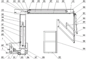
The utility model particularly relates to an all-round orchard operation platform of suspension type has solved at the bottom of the orchard operation platform operation flexibility ratio, the working range is little, the lifting range is limited, to hilly mountain region not applicable, the poor problem of commonality. A suspended omnibearing orchard operating platform comprises a slewing mechanism, a hydraulic motor and a vertical slewing shaft; the upright post type lifting mechanism comprises a telescopic upright post, a lifting driving oil cylinder, an I steering chain wheel and an I chain; the transverse telescopic mechanism comprises a telescopic crossbeam, a telescopic driving oil cylinder, a II steering chain wheel, a II chain, a III steering chain wheel and a III chain; the adjustable platform mechanism comprises a parallel four-bar mechanism, an operation platform body and an adjusting driving oil cylinder; the hydraulic driving device comprises a hydraulic pump, a gearbox and a hydraulic oil tank. The utility model discloses can once only accomplish the operation of two trees whole week, applicable in the hills mountain region, the operating range is big, has effectively improved the operating efficiency, has convenient regulation, factor of safety is high, the advantage that the commonality is strong.
Description
Technical Field
The utility model relates to the field of agricultural machinery, especially, relate to operation platform, specifically are all-round orchard operation platform of suspension type.
Background
At present, the total amount of fruit trees planted in China is huge, but planting terrains are complex and changeable, planting scales are also different, the proportion of hills and mountains is large, and the large-scale specialized planting area is not too large; the comprehensive mechanization levels of the dominant production area and the non-dominant production area of the fruits in China are respectively less than 20 percent and less than 10 percent. And orchard harvest is a weak link for orchard operation. In areas with laggard planting, small scale and complex terrain, mechanization of orchards laggard, branches and leaves are trimmed and picked by climbing to a certain height by using an escalator mostly depending on manpower, and artificial pollination is sometimes needed.
The orchard operation platform in developed countries is suitable for large-scale orchards, the orchard operation platform adopts an electromechanical liquid combination design, the mechanization degree is high, the operation width is large, but the price is high, the orchard operation platform is not suitable for orchard distribution terrain in China, and the orchard operation platform cannot be directly applied in China.
Most of the existing garden machines in China are lifting self-propelled operation platforms, are suitable for orchard operation for leveling lands on a large scale, and generally have the problems of low operation flexibility, small operation range, limited lifting range and inapplicability to hilly and mountain regions. Most of orchard operation platforms in the domestic market are designed according to specific row spacing, the universality is low, and the orchard operation platforms can not be compatible with different row spacing for operation.
SUMMERY OF THE UTILITY MODEL
The utility model discloses a solve at the bottom of the current orchard operation platform operational flexibility ratio, the operation scope is little, the lifting range is limited, to hills mountain region not applicable, the poor problem of commonality, provide an all-round orchard operation platform of suspension type.
The utility model discloses an adopt following technical scheme to realize:
a suspension type omnibearing orchard operating platform comprises a rack, a swing mechanism, a column type lifting mechanism, a transverse telescopic mechanism, an adjustable platform mechanism and a hydraulic driving device; a suspension mechanism is arranged at the left part of the frame;
the swing mechanism comprises a hydraulic motor and a vertical rotating shaft, wherein the base is fixedly connected to the rack, the vertical rotating shaft is positioned on the right side of the hydraulic motor, the middle of the vertical rotating shaft is rotatably supported on the rack, a pinion is fixedly assembled on an output shaft of the hydraulic motor, a large gear meshed with the pinion is fixedly assembled at the bottom of the vertical rotating shaft, and a lower flange plate is horizontally fixed at the top of the vertical rotating shaft;
the column type lifting mechanism comprises an upper flange plate which is positioned at the bottom and fixedly connected with a lower flange plate, a telescopic column is arranged at the upper side of the upper flange plate, the bottom of the telescopic column is fixed with the upper flange plate, and the telescopic column consists of a vertical outer knuckle arm, a vertical middle knuckle arm and a vertical inner knuckle arm which are sequentially sleeved from bottom to top; a lifting driving oil cylinder with an upward piston rod is arranged in an inner cavity of the telescopic stand column, the bottom of a cylinder barrel of the lifting driving oil cylinder is connected to the vertical outer knuckle arm, and a cross-shaped retainer which is in sliding connection with the vertical inner knuckle arm is horizontally fixed in the middle of the cylinder barrel; the top of a piston rod of the lifting driving oil cylinder is provided with an I-shaped steering chain wheel, an I-shaped chain is wound on the I-shaped steering chain wheel, one end of the I-shaped chain is connected to the bottom end of the vertical inner knuckle arm, and the other end of the I-shaped chain is connected to the bottom end of the vertical outer knuckle arm;
the transverse telescopic mechanism comprises two connecting lug plates which are fixedly connected to the top end parts of the vertical inner knuckle arms and are distributed in parallel front and back, a transversely placed telescopic cross beam is fixedly connected between the two connecting lug plates, and the telescopic cross beam consists of a transverse outer knuckle arm, a transverse middle knuckle arm and a transverse inner knuckle arm which are sequentially sleeved from left to right; the inner cavity of the telescopic cross beam is provided with a telescopic driving oil cylinder with a piston rod facing to the left, and the left end part of a cylinder barrel of the telescopic driving oil cylinder is connected with the left end part of the transverse middle-section arm; the left end part of a piston rod of the telescopic driving oil cylinder is connected with the left end part of the transverse outer knuckle arm; a second steering chain wheel is arranged at the right end part of the cylinder barrel of the telescopic driving oil cylinder, a second chain is wound on the second steering chain wheel, one end of the second chain is connected to the left end of the transverse inner knuckle arm, and the other end of the second chain is connected to the left end of the transverse outer knuckle arm; a third steering chain wheel arranged on the transverse middle knuckle arm is arranged below the telescopic driving oil cylinder, a third chain is wound on the third steering chain wheel, one end of the third chain is connected to the left end of the transverse inner knuckle arm, and the other end of the third chain is connected to the right end of the transverse outer knuckle arm;
the adjustable platform mechanism comprises an I-shaped connecting vertical rod fixedly connected to the bottom of the right end of the transverse inner knuckle arm, an operating platform body which is positioned on the left of the I-shaped connecting vertical rod and is positioned below the telescopic cross beam, and a parallel four-bar mechanism arranged between the I-shaped connecting vertical rod and the operating platform body, wherein an adjusting driving oil cylinder which is obliquely arranged from high to low and has a piston rod facing downwards from left to right is arranged on the right side of the I-shaped connecting vertical rod; the cylinder barrel of the adjusting driving oil cylinder is hinged to the upper part of the I-connection vertical rod; the right part of the parallel four-bar mechanism is hinged with a piston rod of the adjusting driving oil cylinder, and the left part of the parallel four-bar mechanism is hinged with the operating platform body;
the hydraulic driving device comprises a hydraulic pump, a gearbox and a hydraulic oil tank which are arranged on the frame; the output shaft of the gearbox is connected with the input shaft of the hydraulic pump; an oil inlet of the hydraulic pump is communicated with an oil outlet of the hydraulic oil tank; the oil outlet of the hydraulic pump is respectively communicated with the hydraulic motor, the lifting driving oil cylinder, the telescopic driving oil cylinder and the adjusting driving oil cylinder through a hydraulic control valve group.
Furthermore, the parallel four-bar mechanism comprises a driving rod, an upper driven rod and a lower driven rod which are hinged to the I-connection vertical rod and are sequentially distributed in parallel from top to bottom; the right end part of the driving rod is hinged with the end part of a piston rod of the adjusting driving oil cylinder, and the left end part of the driving rod is hinged with the middle part of the upper driven rod through a vertical pull rod; the operation platform body is the operation square frame of top open-ended, and its right side is fixed with II and connects the pole setting, and the left end portion of going up the driven lever, the left end portion of lower driven lever all articulate in the upper portion that II connects the pole setting.
Furthermore, the hydraulic control valve group comprises four valve assemblies, and the four valve assemblies are respectively arranged on oil paths of the hydraulic motor, the lifting driving oil cylinder, the telescopic driving oil cylinder and the adjusting driving oil cylinder; the valve assembly comprises an electromagnetic directional valve, a hydraulic lock and a speed regulating valve.
Furthermore, limiting mechanisms are arranged between the vertical outer joint arm and the vertical middle joint arm, between the vertical middle joint arm and the vertical inner joint arm, between the transverse outer joint arm and the transverse middle joint arm, and between the transverse middle joint arm and the transverse inner joint arm, and each limiting mechanism comprises an inner limiting ring and an outer limiting ring; the inner limiting rings are respectively fixed at the top end of the inner side wall of the vertical outer knuckle arm, the top end of the inner side wall of the vertical middle knuckle arm, the right end of the inner side wall of the transverse outer knuckle arm and the right end of the inner side wall of the transverse middle knuckle arm; the outer limiting rings are fixed to the bottom end of the outer side wall of the vertical middle-section arm, the bottom end of the outer side wall of the vertical inner-section arm, the left end of the outer side wall of the transverse middle-section arm and the left end of the outer side wall of the transverse inner-section arm respectively.
Further, a mounting gap located below is reserved between the outer side wall of the transverse outer section arm and the inner side wall of the transverse middle section arm, the third chain penetrates through the outer limiting ring and the mounting gap, and the end portion of the third chain is connected to the inner limiting ring.
Furthermore, two tapered roller bearings which are distributed up and down are arranged in the middle of the vertical rotating shaft, a bearing seat is jointly arranged outside the two tapered roller bearings, and the upper portion of the bearing seat is connected with the frame flange.
Further, the suspension mechanism comprises three pairs of suspension ear plates which are distributed in a triangular mode.
Further, the tooth distribution angle of the big gear is 270 degrees.
The utility model has the advantages of reasonable design reliably, according to traditional orchard operation machinery's requirement, can once only accomplish the operation of two trees whole week, can form a complete set agricultural machinery in addition and use, applicable in the operation in hills mountain region, the orchard of different row plant spacing can be adapted to the omnidirectional operation scope simultaneously, the operation scope is big, the suitability further promotes, has effectively improved the operating efficiency, has convenient regulation, factor of safety is high, the advantage that the commonality is strong, be adapted to the requirement of orchard operation.
Drawings
Fig. 1 is a schematic structural diagram of the present invention;
FIG. 2 is a schematic top view of FIG. 1;
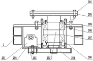
FIG. 3 is a schematic structural diagram of a swing mechanism of the present invention;
fig. 4 is a schematic structural view of the middle column type lifting mechanism of the present invention;
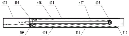
FIG. 5 is a schematic structural view of the middle transverse telescoping mechanism of the present invention;
FIG. 6 is a schematic structural view of an adjustable platform mechanism according to the present invention;
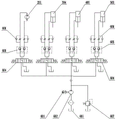
fig. 7 is a schematic connection diagram of the hydraulic driving device of the present invention.
In the figure, 1-a rack, 201-a hydraulic motor, 202-a vertical rotating shaft, 203-a pinion, 204-a bull gear, 205-a lower flange plate, 206-a tapered roller bearing, 207-a bearing seat, 208-a mounting seat, 209-a turntable flange plate, 301-an upper flange plate, 302-a vertical outer knuckle arm, 303-a vertical inner knuckle arm, 304-a lifting driving oil cylinder, 305-a cross-shaped holding frame, 306-an I steering sprocket, 307-an I chain, 401-a connecting lug plate, 402-a transverse outer knuckle arm, 403-a transverse middle knuckle arm, 404-a transverse inner knuckle arm, 405-a telescopic driving oil cylinder, 406-an II steering sprocket, 407-an II chain, 408-an III steering sprocket, 409-an III chain and 410-an inner limit ring, 411-an installation gap, 412-a connecting pin, 413-an inverted U-shaped base, 501-an I-th connecting vertical rod, 502-an operation platform body, 503-an adjusting driving oil cylinder, 504-a driving rod, 505-an upper driven rod, 506-a lower driven rod, 507-a vertical pull rod, 508-a II-th connecting vertical rod, 509-a hinged seat, 601-a hydraulic pump, 602-a gearbox, 603-a hydraulic oil tank, 604-an electromagnetic reversing valve, 605-a hydraulic lock, 606-a speed regulating valve, 607-an overflow valve and 7-a suspension lug plate.
Detailed Description
A suspension type omnibearing orchard operation platform is shown in attached figures 1 and 2 and comprises a rack 1, a swing mechanism, a column type lifting mechanism, a transverse telescopic mechanism, an adjustable platform mechanism and a hydraulic driving device; a suspension mechanism is arranged at the left part of the frame 1;
as shown in fig. 1, fig. 2 and fig. 3, the swing mechanism includes a hydraulic motor 201 whose base is fixedly connected to the frame 1, and a vertical swing shaft 202 located at the right side of the hydraulic motor 201 and whose middle part is rotatably supported on the frame 1, a pinion 203 is fixedly mounted on an output shaft of the hydraulic motor 201, a bull gear 204 engaged with the pinion 203 is fixedly mounted at the bottom of the vertical swing shaft 202, and a lower flange 205 is horizontally fixed at the top;
as shown in fig. 1, fig. 2 and fig. 4, the column lifting mechanism includes an upper flange 301 located at the bottom and fixedly connected to the lower flange 205, a telescopic column fixed to the upper flange 301 at the bottom is provided at the upper side of the upper flange 301, and the telescopic column is composed of a vertical outer arm 302, a vertical middle arm and a vertical inner arm 303 which are sequentially sleeved from bottom to top; a lifting driving oil cylinder 304 with an upward piston rod is arranged in an inner cavity of the telescopic upright post, the bottom of a cylinder barrel of the lifting driving oil cylinder 304 is connected to the vertical outer knuckle arm 302, and a cross-shaped retainer 305 which is in sliding connection with the vertical inner knuckle arm 303 is horizontally fixed in the middle of the cylinder barrel; an I-th steering chain wheel 306 is arranged at the top of a piston rod of the lifting driving oil cylinder 304, an I-th chain 307 is wound on the I-th steering chain wheel 306, one end of the I-th chain 307 is connected to the bottom end of the vertical inner knuckle arm 303, and the other end of the I-th chain 307 is connected to the bottom end of the vertical outer knuckle arm 302;
as shown in fig. 1, fig. 2, and fig. 5, the transverse telescopic mechanism includes two connecting ear plates 401 fixedly connected to the top end portion of the vertical inner arm 303 and distributed in parallel in the front-rear direction, and a transversely disposed telescopic cross beam is fixedly connected between the two connecting ear plates 401, and the telescopic cross beam is composed of a transverse outer arm 402, a transverse middle arm 403, and a transverse inner arm 404 which are sequentially sleeved from left to right; a telescopic driving oil cylinder 405 with a piston rod facing left is arranged in an inner cavity of the telescopic cross beam, and the left end part of a cylinder barrel of the telescopic driving oil cylinder 405 is connected with the left end part of the transverse middle-section arm 403; the left end of the piston rod of the telescopic driving oil cylinder 405 is connected with the left end of the transverse outer knuckle arm 402; a second steering chain wheel 406 is arranged at the right end part of the cylinder barrel of the telescopic driving oil cylinder 405, a second chain 407 is wound on the second steering chain wheel 406, one end of the second chain 407 is connected to the left end of the transverse inner knuckle arm 404, and the other end of the second chain 407 is connected to the left end of the transverse outer knuckle arm 402; a III steering chain wheel 408 mounted on the transverse middle knuckle arm 403 is arranged below the telescopic driving oil cylinder 405, a III chain 409 is wound on the III steering chain wheel 408, one end of the III chain 409 is connected to the left end of the transverse inner knuckle arm 404, and the other end of the III chain 409 is connected to the right end of the transverse outer knuckle arm 402;
as shown in fig. 1, fig. 2, and fig. 6, the adjustable platform mechanism includes an I-connection upright 501 fixedly connected to the bottom of the right end of the transverse inner arm 404, an operating platform body 502 located at the left of the I-connection upright 501 and below the telescopic cross beam, and a parallel four-bar mechanism disposed between the I-connection upright 501 and the operating platform body 502, wherein an adjusting driving cylinder 503 is disposed at the right side of the I-connection upright 501, and has a piston rod inclined to the right and downward; the cylinder barrel of the adjusting driving oil cylinder 503 is hinged to the upper part of the I-shaped connecting vertical rod 501; the right part of the parallel four-bar mechanism is hinged with a piston rod of an adjusting driving oil cylinder 503, and the left part of the parallel four-bar mechanism is hinged with the operation platform body 502;
as shown in fig. 1, fig. 2, and fig. 7, the hydraulic driving device includes a hydraulic pump 601, a transmission 602, and a hydraulic oil tank 603 disposed in the frame 1; the output shaft of the gearbox 602 is connected with the input shaft of the hydraulic pump 601; an oil inlet of the hydraulic pump 601 is communicated with an oil outlet of the hydraulic oil tank 603; the oil outlet of the hydraulic pump 601 is respectively communicated with the hydraulic motor 201, the lifting driving cylinder 304, the telescopic driving cylinder 405 and the adjusting driving cylinder 503 through a hydraulic control valve group.
The utility model realizes the integral rotation of the operating platform through the swing mechanism; the height adjustment of the operating platform close to the suspension end is realized through a column type lifting mechanism, the working principle is that the stroke change of a lifting driving oil cylinder 304 is utilized to drive an I chain 307 to move, and the small displacement is amplified by utilizing a chain and chain wheel mechanism, so that the lifting purpose is realized, and the stroke change of a telescopic column is 2 meters; the adjustment of the distance between the operation platform body 502 and the rack 1 along the horizontal direction is realized through a transverse telescopic mechanism, the working principle is that a three-stage synchronous telescopic structure is utilized, the extension amount of a telescopic driving oil cylinder 405 is changed to drive a chain II 407 or a chain III 409 to move, and a knuckle arm is pulled, so that the change along the transverse distance is realized to adapt to different row spacing; the position of the operation platform body 502 is adjusted through an adjustable platform mechanism, and the working principle is that the operation platform body 502 is lifted and lowered by adjusting the driving oil cylinder 503 to control the motion of the parallel four-bar mechanism; the hydraulic driving device provides power for all-directional movement of the operation platform, the gearbox 602 is installed in the middle of the rack 1, the hydraulic pump 601 is connected with the gearbox 602 through a flange, the flange is internally connected with an output shaft of the gearbox 602 and an input shaft of the hydraulic pump 601 through a coupler, and the hydraulic pump 601 extracts hydraulic oil in the hydraulic oil tank 603 and provides power for the whole operation platform.
When the agricultural machine works, the frame 1 is connected with an agricultural machine (such as an agricultural 50-horsepower tractor) through a suspension mechanism, a power output shaft of the agricultural machine is connected with an input shaft of a gearbox 602, the power of the agricultural machine provides power for a hydraulic pump 601 through the gearbox 602, the transmission ratio of the gearbox 602 is 0.27, the rotating speed of an input end 540r/min is increased to 2000r/min and is output to the hydraulic pump 601, and 14Mp pressure is provided for the hydraulic pump 601; the hydraulic pump 601 respectively delivers the hydraulic oil in the hydraulic oil tank 603 to the hydraulic motor 201, the lifting driving cylinder 304, the telescopic driving cylinder 405 and the adjusting driving cylinder 503 through the hydraulic control valve group, thereby providing required power for the hydraulic motor 201, the lifting driving cylinder 304, the telescopic driving cylinder 405 and the adjusting driving cylinder 503.
When the angle needs to be adjusted, the hydraulic motor 201 drives the pinion 203 to rotate, and under the meshing action of the pinion 203 and the gearwheel 204, the vertical rotating shaft 202 is driven to rotate along a certain direction, and then the lower flange plate 205 and the column type lifting mechanism are driven to rotate, so that the angle of the operating platform is adjusted.
When the height needs to be raised, the piston rod of the lifting driving oil cylinder 304 rises to drive the I-th steering sprocket 306 and the I-th chain 307 to rise, and one end of the I-th chain 307 is connected with the vertical outer knuckle arm 302 to further drive the other end of the I-th chain 307 and the vertical inner knuckle arm 303 to rise, so that the purpose of height rising is achieved. When the height needs to be reduced, the lifting driving oil cylinder 304 drives the piston rod to descend to drive the I-th steering chain wheel 306 to descend, meanwhile, under the action of gravity, the I-th chain 307 and the vertical inner knuckle arm 303 both descend, and in the descending process, the middle part of the I-th chain 307 is always in sliding contact with the I-th steering chain wheel 306, so that the purpose of height descending is achieved.
The adjustment of the lateral position is performed by the actuation of the telescopic actuation cylinder 405. When the stretching is needed, a piston rod of the telescopic driving oil cylinder 405 stretches out, and because the left end part of the piston rod is connected with the left end part of the transverse outer knuckle arm 402, a cylinder barrel of the telescopic driving oil cylinder 405 moves rightwards, so that a II steering chain wheel 406 and an II chain 407 are driven to move rightwards, because one end of the II chain 407 is connected with the left end of the transverse inner knuckle arm 404, and the other end of the II chain 407 is connected with the left end of the transverse outer knuckle arm 402, the II chain 407 moves rightwards, so that the transverse inner knuckle arm 404 moves rightwards, and the stretching of a transverse telescopic mechanism is realized; when the length of the telescopic mechanism needs to be shortened, a piston rod of the telescopic driving oil cylinder 405 retracts to drive a cylinder barrel of the telescopic driving oil cylinder 405 to move leftwards, then the transverse middle-joint arm 403 is driven to transversely move leftwards, the transverse middle-joint arm 403 moves leftwards to drive the III steering chain wheel 408 and the III chain 409 to move leftwards, one end of the III chain 409 is connected to the left end of the transverse inner-joint arm 404, the other end of the III chain 409 is connected to the right end of the transverse outer-joint arm 402, and the III chain 409 moves leftwards to drive the transverse inner-joint arm 404 to move leftwards, so that the length of the transverse telescopic mechanism is shortened.
The position adjustment of the adjustable platform mechanism is completed under the driving of the adjusting driving oil cylinder 503. When the operation platform body 502 needs to move to the right upper side, the piston rod of the driving oil cylinder 503 is adjusted to extend out, the connecting rod of the parallel four-bar mechanism is driven to rotate clockwise, and then the operation platform body 502 is driven to move to the right upper side; when the operation platform body 502 needs to move to the lower left, the piston rod of the driving oil cylinder 503 is adjusted to retract, the connecting rod of the parallel four-bar mechanism is driven to rotate anticlockwise, and then the operation platform body 502 is driven to move to the lower left; thereby realizing the position adjustment of the adjustable platform mechanism.
Under the synergistic action of the slewing mechanism, the column type lifting mechanism, the transverse telescopic mechanism and the adjustable platform mechanism, the omnibearing position adjustment of the operating platform body 502 can be completed, so that the operating platform can complete the whole-circle operation of two trees at one time, and the omnibearing operating range can adapt to orchards with different row spacing. The utility model overcomes at the bottom of the current orchard operation platform operation flexibility ratio, operation scope is little, the lifting range is limited, to hills mountain region not applicable, the poor problem of commonality.
As shown in fig. 1 and fig. 6, the parallel four-bar mechanism includes a driving rod 504, an upper driven rod 505 and a lower driven rod 506 hinged to the I-th connecting upright 501 and distributed in parallel from top to bottom; the right end part of the driving rod 504 is hinged with the end part of a piston rod of the adjusting driving oil cylinder 503, and the left end part is hinged with the middle part of the upper driven rod 505 through a vertical pull rod 507; the operation platform body 502 is an operation frame with an opening at the upper part, a second connecting vertical rod 508 is fixed at the right side of the operation platform body, and the left end part of the upper driven rod 505 and the left end part of the lower driven rod 506 are hinged to the upper part of the second connecting vertical rod 508.
The structural design realizes the change of the height of the operation platform body 502 from the ground by adjusting the extension of the driving oil cylinder 503 to drive the two groups of parallel four-bar mechanisms.
As shown in fig. 7, the hydraulic control valve set includes four valve assemblies, and the four valve assemblies are respectively installed on oil paths of the hydraulic motor 201, the lifting driving cylinder 304, the telescopic driving cylinder 405, and the adjusting driving cylinder 503; the valve assembly includes a solenoid directional valve 604, a hydraulic lock 605, and a speed valve 606.
This structural design passes through the execution of solenoid directional valve 604 control action, guarantees through hydraulic pressure lock 605 that executive component's pressure does not reveal, realizes through governing valve 606 that operating platform body 5020.1 m/s's rising or falling speed and 0.075 r/s's rotation angular velocity have further improved the utility model discloses a structural reliability.
Limiting mechanisms are arranged between the vertical outer joint arm 302 and the vertical middle joint arm, between the vertical middle joint arm and the vertical inner joint arm 303, between the transverse outer joint arm 402 and the transverse middle joint arm 403, and between the transverse middle joint arm 403 and the transverse inner joint arm 404, and each limiting mechanism comprises an inner limiting ring 410 and an outer limiting ring; the inner limiting ring 410 is respectively fixed at the top end of the inner side wall of the vertical outer knuckle arm 302, the top end of the inner side wall of the vertical middle knuckle arm, the right end of the inner side wall of the transverse outer knuckle arm 402 and the right end of the inner side wall of the transverse middle knuckle arm 403; the outer limiting ring is respectively fixed at the bottom end of the outer side wall of the vertical middle-section arm, the bottom end of the outer side wall of the vertical inner-section arm 303, the left end of the outer side wall of the transverse middle-section arm 403 and the left end of the outer side wall of the transverse inner-section arm 404.
Stop gear can prevent deviating from of festival arm, has further improved this operation platform's structural reliability.
As shown in fig. 5, a mounting gap 411 is left between the outer side wall of the transverse outer arm 402 and the inner side wall of the transverse middle arm 403, the third chain 409 penetrates through the outer limiting ring and the mounting gap 411, and the end of the third chain 409 is connected to the inner limiting ring 410.
As shown in fig. 1 and fig. 3, two tapered roller bearings 206 distributed up and down are disposed in the middle of the vertical rotating shaft 202, a bearing seat 207 is disposed outside the two tapered roller bearings 206, and the upper portion of the bearing seat 207 is flange-connected to the frame 1.
The tapered roller bearing 206 and the bearing seat 207 constitute a rotation pair of the vertical rotation shaft 202, thereby improving the rotation supporting effect of the frame 1 on the vertical rotation shaft 202.
As shown in fig. 1 and 2, the suspension mechanism includes three pairs of suspension ear plates 7 distributed in a triangular shape.
This structural design has realized being connected of three-point suspension mode of this operation platform and agricultural machinery, the simple operation nature when having increased this operation platform and connecting.
The teeth of the bull gear 204 are angularly distributed by 270.
This structural design is through the tooth distribution angle that changes gear wheel 204, and it is spacing to have realized this operation platform's machinery to prevent the harm that misoperation brought, avoid promptly falling object to the operating personnel's on the agricultural machinery injury, improved this operation platform's factor of safety.
In the specific implementation process, the size of the operation platform in the contraction state is 750mm multiplied by 1200mm, and the operation platform can bear 200kg of weight.
The hydraulic oil tank 603 is formed by welding steel plates with the thickness of 3mm, has the size of 950 mm multiplied by 250mm multiplied by 500mm, and can contain 118L of hydraulic oil; the hydraulic pump 601 is a CBF-20 type gear pump. The hydraulic motor 201 is of the type GM 5-25. The agricultural machine is preferably a 50 horsepower agricultural tractor and powers the hydraulic pump 601 to provide 14Mpa of pressure. An overflow valve 607 is provided beside the hydraulic oil tank 603.
The specification of the vertical pivot shaft 202 is phi 117 x 330 mm; a rotary table flange plate 209 is horizontally fixed at the right part of the frame 1, and the upper part of the bearing seat 207 is fixedly connected with the rotary table flange plate 209 through bolts. The size of the rotary table flange plate 209 is 610 mm multiplied by 510 mm. A mounting seat 208 is horizontally fixed on the front side of the frame 1, the base of the hydraulic motor 201 is fixedly connected to the mounting seat 208, and the hydraulic motor 201 penetrates through the mounting seat 208. The lower flange plate 205 and the upper flange plate 301 are both square flange plates.
The specification of the vertical outer joint arm 302 is 315mm multiplied by 1550 mm; the specification of the vertical middle-section arm is 307mm multiplied by 1420 mm; the specification of the vertical inner joint arm 303 is 290mm multiplied by 1708 mm; the wall thicknesses of the vertical outer knuckle arm 302, the vertical middle knuckle arm and the vertical inner knuckle arm 303 are all 3mm, and the gaps between the vertical outer knuckle arm 302 and the vertical middle knuckle arm as well as between the vertical middle knuckle arm and the vertical inner knuckle arm 303 are all 0.5 mm; the type of the lifting driving oil cylinder 304 is 50 multiplied by 1000mm of a hydraulic cylinder for a DG vehicle. The four end portions of the cross-shaped retainer 305 are integrally provided with T-shaped sliding blocks, and T-shaped sliding grooves which are connected with the four T-shaped sliding blocks in a sliding mode are formed in the inner side wall of the vertical inner section arm 303.
The specification of the transverse outer joint arm 402 is 254mm multiplied by 188mm multiplied by 3080 mm; the specification of the transverse middle-section arm 403 is 250mm multiplied by 187mm multiplied by 2400 mm; the specification of the transverse inner knuckle arm 404 is 204mm multiplied by 166mm multiplied by 2400 mm; the wall thicknesses of the transverse outer knuckle arm 402, the transverse middle knuckle arm 403 and the transverse inner knuckle arm 404 are all 3mm, and the gaps between the transverse outer knuckle arm 402 and the transverse middle knuckle arm 403 and between the transverse middle knuckle arm 403 and the transverse inner knuckle arm 404 are all 0.5 mm; the telescopic driving cylinder 405 is a DG type hydraulic cylinder for vehicle 40 × 2000 mm. The telescopic cross beam is fixedly connected with the two connecting ear plates 401 through two connecting pins 412 distributed left and right. The two connecting ear plates 401 are fixedly connected with the vertical inner section arm 303 through an inverted U-shaped base 413.
The specification of the active rod 504 is 50mm multiplied by 32mm multiplied by 865 mm; the specifications of the upper driven rod 505 and the lower driven rod 506 are 50mm multiplied by 32mm multiplied by 1265 mm; the specification of the operation platform body 502 is 700mm × 700mm × 1200 mm; the model of the adjusting driving oil cylinder 503 is 40 multiplied by 450 mm. The front side of the I-th connecting upright rod 501 is fixedly connected with a hinge seat 509, and the cylinder barrel of the adjusting driving cylinder 503 is rotatably connected with the hinge seat 509.
Claims (8)
1. The utility model provides an all-round orchard operation platform of suspension type which characterized in that: comprises a frame (1), a swing mechanism, a column type lifting mechanism, a transverse telescopic mechanism, an adjustable platform mechanism and a hydraulic driving device; a suspension mechanism is arranged at the left part of the frame (1);
the swing mechanism comprises a hydraulic motor (201) and a vertical swing shaft (202), wherein the base is fixedly connected to the rack (1), the vertical swing shaft is positioned on the right side of the hydraulic motor (201), the middle of the vertical swing shaft is rotatably supported on the rack (1), a pinion (203) is fixedly assembled on an output shaft of the hydraulic motor (201), a bull gear (204) meshed with the pinion (203) is fixedly assembled at the bottom of the vertical swing shaft (202), and a lower flange plate (205) is horizontally fixed at the top of the vertical swing shaft;
the column type lifting mechanism comprises an upper flange plate (301) which is positioned at the bottom and fixedly connected with a lower flange plate (205), a telescopic column is arranged at the upper side of the upper flange plate (301), the bottom of the telescopic column is fixed with the upper flange plate, and the telescopic column consists of a vertical outer knuckle arm (302), a vertical middle knuckle arm and a vertical inner knuckle arm (303) which are sequentially sleeved from bottom to top; a lifting driving oil cylinder (304) with an upward piston rod is arranged in an inner cavity of the telescopic upright post, the bottom of a cylinder barrel of the lifting driving oil cylinder (304) is connected to the vertical outer knuckle arm (302), and a cross-shaped retainer (305) which is in sliding connection with the vertical inner knuckle arm (303) is horizontally fixed in the middle of the cylinder barrel; an I-shaped steering chain wheel (306) is arranged at the top of a piston rod of the lifting driving oil cylinder (304), an I-shaped chain (307) is wound on the I-shaped steering chain wheel (306), one end of the I-shaped chain (307) is connected to the bottom end of the vertical inner knuckle arm (303), and the other end of the I-shaped chain is connected to the bottom end of the vertical outer knuckle arm (302);
the transverse telescopic mechanism comprises two connecting lug plates (401) which are fixedly connected to the top end of the vertical inner knuckle arm (303) and distributed in parallel from front to back, a transversely placed telescopic cross beam is fixedly connected between the two connecting lug plates (401), and the telescopic cross beam is composed of a transverse outer knuckle arm (402), a transverse middle knuckle arm (403) and a transverse inner knuckle arm (404) which are sequentially sleeved from left to right; a telescopic driving oil cylinder (405) with a piston rod facing left is arranged in an inner cavity of the telescopic cross beam, and the left end part of a cylinder barrel of the telescopic driving oil cylinder (405) is connected with the left end part of the transverse middle-section arm (403); the left end of a piston rod of the telescopic driving oil cylinder (405) is connected with the left end of the transverse outer knuckle arm (402); a second steering chain wheel (406) is arranged at the right end part of the cylinder barrel of the telescopic driving oil cylinder (405), a second chain (407) is wound on the second steering chain wheel (406), one end of the second chain (407) is connected to the left end of the transverse inner knuckle arm (404), and the other end of the second chain is connected to the left end of the transverse outer knuckle arm (402); a III steering chain wheel (408) arranged on the transverse middle knuckle arm (403) is arranged below the telescopic driving oil cylinder (405), a III chain (409) is wound on the III steering chain wheel (408), one end of the III chain (409) is connected to the left end of the transverse inner knuckle arm (404), and the other end of the III chain (409) is connected to the right end of the transverse outer knuckle arm (402);
the adjustable platform mechanism comprises an I-shaped connecting vertical rod (501) fixedly connected to the bottom of the right end of the transverse inner knuckle arm (404), an operating platform body (502) which is positioned on the left of the I-shaped connecting vertical rod (501) and is positioned below the telescopic cross beam, and a parallel four-bar mechanism arranged between the I-shaped connecting vertical rod (501) and the operating platform body (502), wherein an adjusting driving oil cylinder (503) which is obliquely arranged in a left-high-right-low mode and has a piston rod facing to the right is arranged on the right side of the I-shaped connecting vertical rod (501); the cylinder barrel of the adjusting driving oil cylinder (503) is hinged to the upper part of the I-shaped connecting vertical rod (501); the right part of the parallel four-bar mechanism is hinged with a piston rod of an adjusting driving oil cylinder (503), and the left part of the parallel four-bar mechanism is hinged with an operation platform body (502);
the hydraulic driving device comprises a hydraulic pump (601), a gearbox (602) and a hydraulic oil tank (603) which are arranged on the frame (1); an output shaft of the gearbox (602) is connected with an input shaft of the hydraulic pump (601); an oil inlet of the hydraulic pump (601) is communicated with an oil outlet of the hydraulic oil tank (603); an oil outlet of the hydraulic pump (601) is respectively communicated with the hydraulic motor (201), the lifting driving oil cylinder (304), the telescopic driving oil cylinder (405) and the adjusting driving oil cylinder (503) through a hydraulic control valve group.
2. The all-round orchard operation platform of suspension type of claim 1, characterized in that: the parallel four-bar mechanism comprises a driving rod (504), an upper driven rod (505) and a lower driven rod (506), which are hinged to the I-th connecting vertical rod (501) and sequentially distributed in parallel from top to bottom; the right end part of the driving rod (504) is hinged with the end part of a piston rod of the adjusting driving oil cylinder (503), and the left end part is hinged with the middle part of the upper driven rod (505) through a vertical pull rod (507); the operation platform body (502) is an operation frame with an opening at the upper part, a second connecting vertical rod (508) is fixed on the right side of the operation platform body, and the left end part of the upper driven rod (505) and the left end part of the lower driven rod (506) are hinged to the upper part of the second connecting vertical rod (508).
3. The all-round orchard operation platform of suspension type of claim 1, characterized in that: the hydraulic control valve group comprises four valve assemblies, and the four valve assemblies are respectively arranged on oil paths of a hydraulic motor (201), a lifting driving oil cylinder (304), a telescopic driving oil cylinder (405) and an adjusting driving oil cylinder (503); the valve assembly comprises an electromagnetic directional valve (604), a hydraulic lock (605) and a speed regulating valve (606).
4. The all-round orchard operation platform of suspension type of claim 1, characterized in that: limiting mechanisms are arranged between the vertical outer joint arm (302) and the vertical middle joint arm, between the vertical middle joint arm and the vertical inner joint arm (303), between the transverse outer joint arm (402) and the transverse middle joint arm (403), and between the transverse middle joint arm (403) and the transverse inner joint arm (404), and each limiting mechanism comprises an inner limiting ring (410) and an outer limiting ring; the inner limiting ring (410) is respectively fixed at the top end of the inner side wall of the vertical outer knuckle arm (302), the top end of the inner side wall of the vertical middle knuckle arm, the right end of the inner side wall of the transverse outer knuckle arm (402) and the right end of the inner side wall of the transverse middle knuckle arm (403); the outer limiting ring is respectively fixed at the bottom end of the outer side wall of the vertical middle-section arm, the bottom end of the outer side wall of the vertical inner-section arm (303), the left end of the outer side wall of the transverse middle-section arm (403) and the left end of the outer side wall of the transverse inner-section arm (404).
5. The all-round orchard operation platform of suspension type of claim 4, characterized in that: an installation gap (411) located below is reserved between the outer side wall of the transverse outer section arm (402) and the inner side wall of the transverse middle section arm (403), the III chain (409) penetrates through the outer limiting ring and the installation gap (411), and the end part of the III chain (409) is connected to the inner limiting ring (410).
6. The all-round orchard operation platform of suspension type of claim 1, characterized in that: two tapered roller bearings (206) which are distributed up and down are arranged in the middle of the vertical rotating shaft (202), a bearing seat (207) is arranged outside the two tapered roller bearings (206), and the upper part of the bearing seat (207) is connected with the frame (1) through a flange.
7. The all-round orchard operation platform of suspension type of claim 1, characterized in that: the suspension mechanism comprises three pairs of suspension ear plates (7) which are distributed in a triangular manner.
8. The all-round orchard operation platform of suspension type of claim 1, characterized in that: the tooth distribution angle of the large gear (204) is 270 degrees.
Priority Applications (1)
| Application Number | Priority Date | Filing Date | Title |
|---|---|---|---|
| CN202221008302.XU CN217064632U (en) | 2022-04-28 | 2022-04-28 | Suspension type all-dimensional orchard operation platform |
Applications Claiming Priority (1)
| Application Number | Priority Date | Filing Date | Title |
|---|---|---|---|
| CN202221008302.XU CN217064632U (en) | 2022-04-28 | 2022-04-28 | Suspension type all-dimensional orchard operation platform |
Publications (1)
| Publication Number | Publication Date |
|---|---|
| CN217064632U true CN217064632U (en) | 2022-07-29 |
Family
ID=82503634
Family Applications (1)
| Application Number | Title | Priority Date | Filing Date |
|---|---|---|---|
| CN202221008302.XU Expired - Fee Related CN217064632U (en) | 2022-04-28 | 2022-04-28 | Suspension type all-dimensional orchard operation platform |
Country Status (1)
| Country | Link |
|---|---|
| CN (1) | CN217064632U (en) |
-
2022
- 2022-04-28 CN CN202221008302.XU patent/CN217064632U/en not_active Expired - Fee Related
Similar Documents
| Publication | Publication Date | Title |
|---|---|---|
| CN103329878B (en) | New-concept intelligent multifunctional spaying machine chassis | |
| CN206307958U (en) | One kind can transversal stretching greenhouse transport vehicle hoistable platform | |
| CN102239763A (en) | Tobacco-seedling ridge-height self-adaptable automatic-guiding transplanter | |
| CN203399635U (en) | New concept intelligent multifunctional spraying machine chassis | |
| CN217064632U (en) | Suspension type all-dimensional orchard operation platform | |
| CN210900260U (en) | Full-automatic transplanting combined machine | |
| CN107364488A (en) | agricultural omni-directional wheel | |
| CN103355014A (en) | Spacing adjustable type double-ditch deep ploughing machine | |
| CN104322472A (en) | Electric remote-control electrostatic adjustable profiling sprayer | |
| CN212278819U (en) | Mini-tiller hanging type small vegetable transplanter | |
| CN114616983A (en) | Suspension type all-dimensional orchard operating platform | |
| CN104351156A (en) | Electric remote-control electrostatic adjustable profile modeling spray method | |
| CN207208178U (en) | A kind of agricultural omni-directional wheel | |
| CN102726161B (en) | Garlic combined harvester | |
| CN215922153U (en) | Agricultural machinery equipment terraced fields and irrigation canals and ditches mechanism of crossing | |
| CN203505042U (en) | Garlic harvesting device capable of harvesting two rows of garlic | |
| CN204157525U (en) | The adjustable profile modeling spray equipment of a kind of electric remote control electrostatic | |
| CN113924836A (en) | Agricultural machinery equipment terraced fields and irrigation canals and ditches mechanism of crossing | |
| CN202364566U (en) | Farmland harvester | |
| CN208540463U (en) | A kind of agricultural planting frame with regulatory function | |
| CN109257982A (en) | A kind of agricultural machinery seedling separation device | |
| CN106416461B (en) | Hand-held double-tail-wheel cultivator | |
| CN212813780U (en) | Longitudinal hydraulic driving mechanism of plant protection machine | |
| CN204796046U (en) | Powder ridge deep ploughing subsoiler | |
| CN113580843B (en) | Bionic connecting rod and paddy field impeller with adjustable in-out soil angle |
Legal Events
| Date | Code | Title | Description |
|---|---|---|---|
| GR01 | Patent grant | ||
| GR01 | Patent grant | ||
| CF01 | Termination of patent right due to non-payment of annual fee |
Granted publication date: 20220729 |