CN202364566U - Farmland harvester - Google Patents
Farmland harvester Download PDFInfo
- Publication number
- CN202364566U CN202364566U CN2011203887748U CN201120388774U CN202364566U CN 202364566 U CN202364566 U CN 202364566U CN 2011203887748 U CN2011203887748 U CN 2011203887748U CN 201120388774 U CN201120388774 U CN 201120388774U CN 202364566 U CN202364566 U CN 202364566U
- Authority
- CN
- China
- Prior art keywords
- frame
- results
- wheel
- harvesting
- driving wheel
- Prior art date
- Legal status (The legal status is an assumption and is not a legal conclusion. Google has not performed a legal analysis and makes no representation as to the accuracy of the status listed.)
- Expired - Fee Related
Links
Images

Abstract
The utility model discloses a farmland harvester, which comprises a frame, a steering mechanism, an engine, a gearbox, a hydraulic pump, a steering wheel and a driving wheel, wherein the gearbox is in transmission connection with a rear axle assembly, and the rear axle assembly is fixed on the top of the frame. The farmland harvester is characterized in that: the steering wheel is arranged at the front end of the frame; the driving wheel comprises driving wheels and transmission wheels; the rear part of the frame is fixedly connected with a harvesting device; the left end and the right end of the rear axle assembly are fixedly connected with transmission shafts provided with power wheels; the harvesting device comprises a harvesting frame, support wheels symmetrically arranged on the harvesting frame, a spading device arranged on the harvesting frame and a sliding connection device arranged at the front end of the harvesting frame; and a support wheel adjusting device is arranged between the support wheels and the harvesting frame. The farmland harvester is harvesting machinery, the harvesting efficiency is obviously improved, and the labor intensity is low; meanwhile, the farmland harvester has a tricycle structure and can adapt to different farmland.
Description
Technical field
The utility model relates to agricultural mechanical field, specifically, relates to a kind of rural area reaping machine.
Background technology
At present, in the farmland, orchard or booth, people are to the rhizomes of crops or be grown in underground fruit, adopt the mode of artificial results mostly, and efficient is low, and labour intensity is big.And the harvesting apparatus fixed-site of some present rural area harvest machineries only is applicable to a small amount of farmland, and is difficult to be applied to most farmland, and the scope of application is little.
Summary of the invention
The purpose of the utility model is to overcome above-mentioned defective, and a kind of harvesting apparatus adjustable positions is provided, and is applied widely, and the rural area reaping machine of walking stable.
For addressing the above problem, the technical scheme that the utility model adopted is:
A kind of rural area reaping machine; Comprise frame, steering mechanism, engine, gearbox, hydraulic pump and by the deflecting roller of steering mechanism's control with by the driving wheel of gearbox control; The gearbox rear axle assy that is in transmission connection; Rear axle assy is fixed on the top of frame, it is characterized in that: said deflecting roller is provided with one, is arranged on the front end of frame; Said driving wheel comprises that symmetry is installed in the driving wheel of frame lower, on the driving wheel respectively with drive is installed; The rear portion of said frame is provided with and is fixedly connected with harvesting apparatus;
The right ends of said rear axle assy is fixedly connected with power transmission shaft respectively, and the end of power transmission shaft is installed on the frame through bearing block respectively; Be separately installed with power wheel on the power transmission shaft, power wheel is respectively through the driving-belt drive that is in transmission connection;
Said harvesting apparatus comprises that results frame, symmetry are installed in the support wheel of results frame, are arranged on the sliding connecting device that the shovel on the results frame goes out device and is arranged on results frame front end; Be provided with the support wheel adjusting device between said support wheel and the results frame, shovel out to be provided with between device and the results frame and shovel out adjusting device.
Further say:
Said deflecting roller is located at the dead ahead of one of them driving wheel, and the angle that the line between the line between the center of above-mentioned driving wheel and the center of deflecting roller and the center of two driving wheels forms is the right angle.
The said mechanism that is slidingly connected comprises slide bar that is fixedly mounted on frame rear end and the sliding sleeve that is fixedly connected with the results frame, and the sliding sleeve cover is connected on the slide bar.
Be provided with the packaged type elevator between said results frame and the frame; Said packaged type elevator comprises that the portable holder that is installed in frame top, the holder that is arranged on the reaping machine top of the trellis and two ends are fixedly mounted on the lifting hydraulic cylinder on portable holder and the holder respectively, and lifting hydraulic cylinder is communicated with through oil pipe with hydraulic pump; Be provided with mobile adjusting device between portable holder and the frame.
Owing to adopted technique scheme, compared with prior art, the utility model is a harvest machinery; Results efficient significantly improves, and labour intensity is little, simultaneously; The utility model adopts three wheeled structures, and a front-wheel is a deflecting roller, and two trailing wheels are driving wheel; Through sliding connecting device and the acting in conjunction of packaged type elevator, regulate the position of harvesting apparatus within the specific limits, make the utility model can adapt to multiple field.
Description of drawings
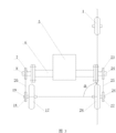
Fig. 1 is the structural representation of a kind of embodiment of the utility model;
Fig. 2 is the structural representation of harvesting apparatus among the embodiment of the utility model;
Fig. 3 is that the position of deflecting roller described in the embodiment of the utility model and two driving wheels concerns sketch map.
Below in conjunction with accompanying drawing and embodiment the utility model is done further description.
Embodiment
Embodiment:
A kind of rural area reaping machine; As shown in Figure 1; Comprise frame 1, steering mechanism 3, engine 4, gearbox 5, hydraulic pump 2 and by the deflecting roller 22 of steering mechanism's 3 controls with by the driving wheel of gearbox 5 controls, gearbox 5 rear axle assy 6 that is in transmission connection, rear axle assy 6 is fixed on the top of frame.Deflecting roller 22 is provided with one, is arranged on the front end of frame 1.Driving wheel comprises that symmetry is installed in the driving wheel 17,28 of frame lower, on the driving wheel 17,28 respectively with drive 19,26 is installed.The rear portion of said frame is provided with and is fixedly connected with harvesting apparatus.
The right ends of said rear axle assy 6 is fixedly connected with power transmission shaft 7,23 respectively, and the end of power transmission shaft 7,23 is installed on the frame through bearing block respectively.Be separately installed with power wheel 8,24 on the power transmission shaft, power wheel 8,24 is respectively through driving- belt 20,25 drive 19,26 that is in transmission connection;
As shown in Figure 2, harvesting apparatus comprises that results frame 16, symmetry are installed in the support wheel 14 of results frame, are arranged on the sliding connecting device that the shovel on the results frame goes out device 15 and is arranged on results frame 16 front ends.Be provided with support wheel adjusting device 13 between support wheel 14 and the results frame 16, shovel out to be provided with between device 15 and the results frame and shovel out adjusting device 12.
The mechanism that is slidingly connected comprises the slide bar 18 that is fixedly mounted on frame rear end and the sliding sleeve 29 that is fixedly connected with the results frame, and sliding sleeve 29 overlaps and is connected on the slide bar.Be provided with the packaged type elevator between results frame and the frame; Said packaged type elevator comprises that the portable holder 9 that is installed in frame top, the holder 11 that is arranged on the reaping machine top of the trellis and two ends are fixedly mounted on the lifting hydraulic cylinder 10 on portable holder 9 and the holder 11 respectively, and lifting hydraulic cylinder 10 is communicated with through oil pipe with hydraulic pump, and lifting hydraulic cylinder 10 is worked under the effect of hydraulic pump; According to actual conditions; Hydraulic stem when not working on the hydraulic cylinder shrinks, and harvesting apparatus is lifted, and hydraulic stem stretches out during work; Harvesting apparatus is put down, carry out harvest operation.Be provided with between portable holder and the frame and move adjusting device 21.In the present embodiment, mobile adjusting device can be a spiro rod regulating device, and portable holder is threaded on the screw rod, and screw rod is fixed on frame top through bearing block.When needing to move; As long as rotating screw bolt just can drive portable holder and move; Be fixedly mounted on lifting hydraulic cylinder on the portable holder also along with moving, same drive results frame moves through sliding on the slide bar, reaches the purpose of regulating the results shelf position.In addition, mobile adjusting device also can be the set bolt of adjustable positions, is provided with through hole corresponding with it at frame top, and according to actual needs, the through hole of selecting diverse location reaches the purpose of regulating the results shelf position through bolt installation and moving formula holder.
On harvesting apparatus, shovel out device 15 and can shovel out height of devices through shoveling out adjusting device 12 adjustings, support wheel 14 is through the height of support wheel adjusting device 13 adjustable support wheel.Shovel out adjusting device and the acting in conjunction of support wheel adjusting device, regulate the operating position of harvesting apparatus, can be at the completion harvest operation under the different geographical conditions.
As shown in Figure 3, deflecting roller 22 is located at the dead ahead of one of them driving wheel, and the angle that the line between the line between the center of above-mentioned driving wheel and the center of deflecting roller and the center of two driving wheels forms is the right angle.Such design makes the reaping machine working stability, and is little to the destruction in field.
In addition, brake gear, put into gear device and arrangement of clutch all are to adopt prior art, repeat no more at this.
Claims (4)
1. rural area reaping machine; Comprise frame (1), steering mechanism (3), engine (4), gearbox (5), hydraulic pump (2) and by the deflecting roller (22) of steering mechanism (3) control with by the driving wheel of gearbox (5) control; Gearbox (5) rear axle assy (6) that is in transmission connection; Rear axle assy (6) is fixed on the top of frame (1), it is characterized in that: said deflecting roller (22) is provided with one, is arranged on the front end of frame (1); Said driving wheel comprises that symmetry is installed in the driving wheel of frame (1) bottom (17,28), on the driving wheel (17,28) respectively with drive (19,26) is installed; The rear portion of said frame (1) is provided with and is fixedly connected with harvesting apparatus;
The right ends of said rear axle assy (6) is fixedly connected with power transmission shaft (7,23) respectively, and the end of power transmission shaft (7,23) is installed on the frame (1) through bearing block respectively; Be separately installed with power wheel (8,24) on the power transmission shaft (7,23), power wheel (8,24) is respectively through driving-belt (20, the 25) drive that is in transmission connection (19,26);
Said harvesting apparatus comprises that results frame (16), symmetry are installed in the support wheel (14) of results frame, are arranged on the jockey that the shovel on the results frame goes out device (15) and is arranged on results frame (16) front end; Be provided with support wheel adjusting device (13) between said support wheel (14) and the results frames (16), shovel out to be provided with between device (15) and the results frames (16) and shovel out adjusting device (12).
2. the rural area rainer adjustable according to the said wheelspan of claim 1; It is characterized in that: said deflecting roller (22) is located at the dead ahead of one of them driving wheel, and the angle a that the line between the line between the center of the center of above-mentioned driving wheel and deflecting roller (22) and the center of two driving wheels forms is the right angle.
3. rural area according to claim 1 reaping machine; It is characterized in that: said bindiny mechanism comprises slide bar (18) that is fixedly mounted on frame (1) rear end and the sliding sleeve (29) that is fixedly connected with results frames (16), and sliding sleeve (29) cover is connected on the slide bar (18).
4. rural area according to claim 3 reaping machine; It is characterized in that: be provided with the packaged type elevator between said results frame and the frame; Said packaged type elevator comprises that the portable holder (9) that is installed in frame (1) top, holder (11) and the two ends that are arranged on results frame (16) top are fixedly mounted on the lifting hydraulic cylinder (10) on portable holder (9) and the holder (11) respectively, and lifting hydraulic cylinder (10) is communicated with through oil pipe with hydraulic pump (2); Be provided with mobile adjusting device (21) between portable holder (9) and the frame (1).
Priority Applications (1)
| Application Number | Priority Date | Filing Date | Title |
|---|---|---|---|
| CN2011203887748U CN202364566U (en) | 2011-10-13 | 2011-10-13 | Farmland harvester |
Applications Claiming Priority (1)
| Application Number | Priority Date | Filing Date | Title |
|---|---|---|---|
| CN2011203887748U CN202364566U (en) | 2011-10-13 | 2011-10-13 | Farmland harvester |
Publications (1)
| Publication Number | Publication Date |
|---|---|
| CN202364566U true CN202364566U (en) | 2012-08-08 |
Family
ID=46588299
Family Applications (1)
| Application Number | Title | Priority Date | Filing Date |
|---|---|---|---|
| CN2011203887748U Expired - Fee Related CN202364566U (en) | 2011-10-13 | 2011-10-13 | Farmland harvester |
Country Status (1)
| Country | Link |
|---|---|
| CN (1) | CN202364566U (en) |
Cited By (2)
| Publication number | Priority date | Publication date | Assignee | Title |
|---|---|---|---|---|
| CN103650736A (en) * | 2012-09-16 | 2014-03-26 | 马灿魁 | Improved simple garlic harvester |
| CN104842779A (en) * | 2015-05-19 | 2015-08-19 | 青岛仁通机械有限公司 | Leek harvester with high ground clearance |
-
2011
- 2011-10-13 CN CN2011203887748U patent/CN202364566U/en not_active Expired - Fee Related
Cited By (2)
| Publication number | Priority date | Publication date | Assignee | Title |
|---|---|---|---|---|
| CN103650736A (en) * | 2012-09-16 | 2014-03-26 | 马灿魁 | Improved simple garlic harvester |
| CN104842779A (en) * | 2015-05-19 | 2015-08-19 | 青岛仁通机械有限公司 | Leek harvester with high ground clearance |
Similar Documents
| Publication | Publication Date | Title |
|---|---|---|
| CN204653503U (en) | A kind of adjustable for height high-clearance sprayer full hydraulic drive chassis and hydraulic system thereof | |
| CN200988514Y (en) | Crawler tractor of liftable machine body | |
| CN202958118U (en) | Full-hydraulic drive two-dimensional horizontally-moving lifting type farm-oriented car frame | |
| CN103144498B (en) | A kind of automatic lifting drive axle | |
| CN202364566U (en) | Farmland harvester | |
| CN204968357U (en) | Self -propelled rotary cultivator | |
| CN205378551U (en) | Header linkage type crawler -type maize picker that skins | |
| CN201976412U (en) | Subsoiling and fertilizing machine for tea garden | |
| CN204907175U (en) | Self -propelled round is dragged sugarcane to cut machine of shop | |
| CN204335464U (en) | The clear native machine of burying grapevine | |
| CN106489337B (en) | High-clearance caterpillar band type field working vehicle | |
| CN204994229U (en) | Novel track rotary cultivator | |
| CN105684825A (en) | A vine burying and soil clearing machine for grapes | |
| CN203608536U (en) | Well cellar machine for planting tobacco | |
| CN202738387U (en) | Hydraulic system for rotary cultivators | |
| CN205755365U (en) | Farmland operation tractor | |
| CN200969737Y (en) | Field weeder and fertilizer spreader | |
| CN205546479U (en) | Agricultural ditching machines that loosen soil | |
| CN205196245U (en) | Weeder | |
| CN201119294Y (en) | Garlic harvester | |
| CN2588771Y (en) | Farmland automatic flush coater | |
| CN205357095U (en) | Overhead intertillage fertilizer distributor of tricycle | |
| CN204047029U (en) | A kind of single-wheel hand-held hoeing machine | |
| CN205284154U (en) | Potato, peanut harvester | |
| CN103999590B (en) | Three-wheel field operating vehicle is pinched, sprays, is intertilled hydraulic lifting system |
Legal Events
| Date | Code | Title | Description |
|---|---|---|---|
| C14 | Grant of patent or utility model | ||
| GR01 | Patent grant | ||
| CF01 | Termination of patent right due to non-payment of annual fee |
Granted publication date: 20120808 Termination date: 20151013 |
|
| EXPY | Termination of patent right or utility model |