CN216832454U - Box folding machine - Google Patents
Box folding machine Download PDFInfo
- Publication number
- CN216832454U CN216832454U CN202122753410.1U CN202122753410U CN216832454U CN 216832454 U CN216832454 U CN 216832454U CN 202122753410 U CN202122753410 U CN 202122753410U CN 216832454 U CN216832454 U CN 216832454U
- Authority
- CN
- China
- Prior art keywords
- box body
- plate
- box
- pushing
- cylinder
- Prior art date
- Legal status (The legal status is an assumption and is not a legal conclusion. Google has not performed a legal analysis and makes no representation as to the accuracy of the status listed.)
- Active
Links
Images


Landscapes
- Making Paper Articles (AREA)
Abstract
The utility model provides a box folding machine, which comprises a box body feeding groove and a box body adsorption mechanism, wherein the box body adsorption mechanism adsorbs a box body paperboard from the box body feeding groove and positions the box body paperboard; the lateral pushing mechanism is used for pushing and unfolding the folded box body into a solid shape, and a first bottom turnover mechanism and a second bottom turnover mechanism are arranged at the lower part of the lateral pushing mechanism; the box body adsorption device lower part is equipped with the third bottom and turns over a mechanism, and this book box machine can every a set of box body of unloading automatically to absorb the box body cardboard and fix a position through adsorption device, set up folding mechanism respectively to box body lower part and upper portion in proper order again, can turn over the portion of turning over of a box body simultaneously in proper order, quick shaping, and the unloading improves work efficiency greatly, and reasonable structure turns over the bad rate of turning over of reduction box body.
Description
Technical Field
The utility model relates to the field of automation equipment, in particular to a box folding machine.
Background
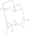
The packing box is used for packing the product, and the packing box is a common product packing tool at present, and the packing box can not only ensure the product safety in the product transportation process, but also improve the product grade. Paper packing carton is simple because of its self production technology, easy operation, advantage such as low price is by extensive use, paper packing carton on the market at present mostly all is foldable packing carton, the prototype is stamping forming's hardboard usually, as shown in fig. 1, be the folding portion including four sides and four sides lower part, and four sides and folding portion have the folding seal of predetermineeing, be convenient for turn over, the folding portion of four sides overlaps each other and can realize the shaping, if through manual operation, the efficiency is extremely low, the development of present era has not been adapted for early, when folding the box through the equipment, because the shoes box folder that CN 104369426B disclosed, moreover, the structure is complicated, and there is not reasonable mechanism of going up the unloading, can't be applicable to as shown in fig. 1 the box body, the folding portion of bottom can't turn over simultaneously and put in place, and break the box body cardboard easily.
SUMMERY OF THE UTILITY MODEL
In order to solve the technical problem, the utility model provides a box folding machine which comprises a box body feeding groove and a box body adsorption mechanism, wherein the box body adsorption mechanism adsorbs and positions a box body paperboard from the box body feeding groove;
the lateral pushing mechanism is used for pushing and unfolding the folded box body into a solid shape, and a first bottom turnover mechanism and a second bottom turnover mechanism are arranged at the lower part of the lateral pushing mechanism; and a third bottom turnover mechanism is arranged at the lower part of the box body adsorption mechanism.
Preferably, the box body blanking groove comprises a material carrying frame which is obliquely arranged, the tail end of the material carrying frame is provided with a limiting mechanism, and the inner wall of the tail end of the material carrying frame is provided with a semi-cylindrical stop block; the carton carrying frame is characterized in that sliding grooves are formed in two sides of the carrying frame, a pressing rod is arranged between the sliding grooves in a sliding connection mode, rolling wheels are arranged at two ends of the pressing rod and clamped in the sliding grooves, and the pressing rod presses the upper portions of the carton body paperboards arranged in the carrying frame in sequence.
Preferably, the limiting mechanism comprises a bottom plate located at the lower part of the material loading frame, the lower part of the bottom plate is connected with a screw rod mechanism, and a limiting baffle is fixed on the bottom plate.
Preferably, the box body adsorption mechanism comprises an XY axis module, a vacuum adsorption plate is connected to the sliding end of the XY axis module, and the vacuum adsorption plate faces the box body blanking groove.
Preferably, the lateral pushing assembly comprises a lateral pushing cylinder, the output end of the lateral pushing cylinder is provided with a pushing plate, and the output end of the pushing plate is provided with a curved surface portion.
Preferably, the edge folding mechanism comprises a rotary cylinder, a connecting rod is arranged at the output end of the rotary cylinder, and a first turning plate is arranged at the end part of the connecting rod.
Preferably, the first bottom turnover mechanism comprises a fixed plate, a rotating shaft is rotatably connected to the fixed plate, a pushing block is eccentrically arranged on the rotating shaft, a pushing cylinder is rotatably connected to the pushing block, the other end of the pushing cylinder is rotatably connected to the fixed plate, a second turnover plate is arranged at the end part of the rotating shaft, and the second turnover plate points to the box body blanking groove.
Preferably, the second bottom turnover mechanism comprises a transverse plate, a push-pull cylinder is arranged at the lower part of the transverse plate, the output end of the push-pull cylinder is connected with a fourth turnover plate, and the fourth turnover plate is rotatably connected with the end part of the transverse plate.
Preferably, the third bottom turnover mechanism comprises a vertical plate fixed at the bottom of the box body blanking groove, the vertical plate is vertically and slidably connected with a sliding plate, the lower part of the sliding plate is connected with a first jacking cylinder, the output end of the first jacking cylinder is fixed with the sliding plate, the sliding plate is rotatably connected with a second jacking cylinder, the output end of the second jacking cylinder is rotatably connected with a third turnover plate, and one side of the third turnover plate is rotatably connected with the sliding plate.
Preferably, still include box body output mechanism, box body output mechanism includes the conveyer belt, the conveyer belt is located box body adsorption apparatus constructs one side.
The box folding machine provided by the utility model has the following beneficial effects: this roll over box machine can every a set of box body of unloading automatically to absorb the box body cardboard and fix a position through adsorption apparatus, set up folding mechanism respectively to box body lower part and upper portion in proper order again, can turn over the book portion of turning over of the box body simultaneously in proper order, quick shaping, and the unloading improves work efficiency greatly, and reasonable structure turns over the bad rate of turning over the book that reduces the box body.
Drawings
In order to more clearly illustrate the technical solutions in the embodiments of the present invention, the drawings used in the description of the embodiments will be briefly introduced below.
FIG. 1 is a schematic illustration of a prior art carton blank;
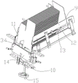
FIG. 2 is a schematic view of the overall structure of the present invention;
FIG. 3 is a schematic view of the magazine of the present invention;
FIG. 4 is a schematic view of a cassette adsorption mechanism of the present invention;
FIG. 5 is a schematic view of the position of each folding mechanism of the present invention;
FIG. 6 is a schematic view of a first bottom folding mechanism of the present invention;
FIG. 7 is a schematic view of a second bottom-folding mechanism and a third bottom-folding mechanism of the present invention;
FIG. 8 is a schematic diagram of a lateral pushing assembly for pushing a box to form a box according to the present invention;
wherein, 1, a box body blanking groove; 2. a box body adsorption mechanism; 3. a lateral pushing assembly; 4. positioning a plate; 5. A first bottom folding mechanism; 6. a second bottom folding mechanism; 7. a third bottom folding mechanism; 8. a flanging mechanism; 9. a material loading frame; 10. a limiting mechanism; 11. a semi-cylindrical stopper; 12. a chute; 13. a roller; 14. A base plate; 15. a screw mechanism; 16. an XY axis module; 17. a vacuum adsorption plate; 18. a side push cylinder; 19. A rotating cylinder; 20. a first flap; 21. a fixing plate; 22. a rotating shaft; 23. a push block; 24. a push cylinder; 25. a second flap; 26. a transverse plate; 27. a push-pull cylinder; 28. a fourth turning plate; 29. a vertical plate; 30. a slide plate; 31. a second jacking cylinder; 32. a third turning plate; 33. a box body output mechanism; 34. a limit baffle; 35. Pushing the plate; 36. the first jacking cylinder.
Detailed Description
The technical solution in the embodiments of the present invention will be clearly and completely described below with reference to the accompanying drawings in the embodiments of the present invention.
As shown in fig. 2, the utility model provides a box folding machine, which comprises a box body feeding groove 1 and a box body adsorption mechanism 2, wherein the box body adsorption mechanism 2 adsorbs a box body paperboard from the box body feeding groove 1 and positions the box body paperboard, two sides of the box body adsorption mechanism 2 are respectively provided with a lateral pushing assembly 3 and a positioning plate 4, and edge folding mechanisms 8 are respectively arranged above and below the positioning plate 4; of course the whole mechanism is externally provided with a housing (not shown in the figures) and in particular,
As shown in fig. 3, the box body feeding trough 1 comprises a material carrying frame 9 which is obliquely arranged, the tail end of the material carrying frame 9 is provided with a limiting mechanism 10, and the inner wall of the tail end of the material carrying frame 9 is provided with a semi-cylindrical stop 11; the two sides of the material carrying frame 9 are provided with chutes 12, a pressure bar (in the figure, the pressure bar is shielded by paper boards) is arranged between the chutes 12 in a sliding connection way, two ends of the pressure bar are provided with rollers 13, the rollers 13 are clamped in the chutes 12, the pressure bar presses the upper parts of the box body paper boards sequentially arranged in the material carrying frame 9, the material carrying frame 9 is obliquely arranged, two sides of the extending direction of the material carrying frame 9 are provided with baffles, the baffles are provided with chutes 12, the pressure bar is clamped in the chute 12 through the rollers 13 and can move along the chute 12, when the superposed box body paper boards are arranged in the material carrying frame 9, the pressure bar presses the upper parts of the superposed box body paper boards through the self weight, a semi-cylindrical stop block 11 arranged on the inner wall of the output end position of the material carrying frame 9 limits all the box body paper boards, after one box body paper board is taken away through the box body adsorption mechanism 2, the pressure bar downwards along the chute 12 to push the position of one box body paper board, the box bodies are ensured to be compact, and the box body adsorption mechanism 2 is convenient to absorb the paper boards.
Here, it is to be noted that: in order to guarantee that the placement of every box body position is correct, 1 department of silo has set up stop gear 10 under the box body, including being located carry the bottom plate 14 of the 9 lower parts of work or material rest, 14 sub-unit connections on the bottom plate have lead screw mechanism 15, be fixed with limit baffle 34 on the bottom plate 14, limit baffle 34's position is the breach position on the box body cardboard, guarantees that every box body cardboard places the unanimity, if place the error, because limit baffle 34's setting, box body adsorption mechanism 2 can't adsorb and take away, stops the machine promptly and corrects.
As shown in fig. 4, the box body adsorption mechanism 2 is arranged on the upper portion of the output end of the box body blanking slot 1, the box body adsorption mechanism 2 comprises an XY axis module 16, a vacuum adsorption plate 17 is connected to the sliding end of the XY axis module 16, the vacuum adsorption plate 17 faces the box body blanking slot 1, the XY axis module 16 can move in the vertical direction and move towards the opening of the box body blanking slot 1, the vacuum adsorption plate 17 is close to the box body paperboard and then absorbs the box body paperboard and moves along the positioning plate 4 through the XY axis module 16, the positioning plate 4 is arranged towards the blanking slot, the lateral pushing assembly 3 is pushed out when the vacuum adsorption plate 17 pulls the box body paperboard, the lateral pushing assembly 3 comprises a lateral pushing cylinder 18, the output end of the lateral pushing cylinder 18 is provided with a pushing plate 35, the end of the pushing plate 35 is provided with a curved surface portion, and the structure of the pushing plate 35 is the same as that of the positioning plate 4, but set up with 4 symmetries of locating plate, the in-process of box body cardboard is drawn and is pulled to box body adsorption apparatus structure 2, promote cylinder 24 and stretch out, and promote push pedal 35 and stretch out, the opposite direction that the orientation and the box body taken out is stretched out, promote the box body cardboard this moment, cooperation locating plate 4, can inject the box body cardboard and open and become the solid box body, as shown in figure 8, at this moment, the bottom and the top of box body all do not turn over the book, then the hem mechanism 8 of cooperation side this moment, first bottom turns over a book mechanism 5, second bottom turns over a book mechanism 6 and a third bottom turns over a book mechanism 7 and turns over a book, above-mentioned mechanism is located around the fashioned solid box body of shaping respectively, specific theory: the lower part of the lateral pushing mechanism is provided with a first bottom turnover mechanism 5 and a second bottom turnover mechanism 6; and a third bottom turnover mechanism 7 is arranged at the lower part of the box body adsorption mechanism 2.
As shown in fig. 5, the edge folding mechanism 8 includes a rotary cylinder 19, the rotary cylinders 19 of the two groups of edge folding mechanisms 8 are respectively fixed on the upper portion and the lower portion of the positioning plate 4, a connecting rod is arranged at the output end of the rotary cylinder 19, a first turning plate 20 is arranged at the end of the connecting rod, the rotary cylinder 19 rotates to drive the first turning plate 20 to press the upper portion and the lower portion of the box body to be turned into the box body, namely, the positions a and b in fig. 1, and meanwhile, the first turning plate 20 on the upper portion can also play a role in positioning the box body.
Subsequently, turn over the e and d part of box body respectively through first bottom turnover mechanism 5 and second bottom turnover mechanism 6, specific saying so: as shown in fig. 7, the second bottom-folding mechanism 6 includes: the second bottom turnover mechanism 6 comprises a transverse plate 26, a push-pull air cylinder 27 is arranged at the lower part of the transverse plate 26, the output end of the push-pull air cylinder 27 is connected with a fourth turnover plate 28, the fourth turnover plate 28 is rotatably connected with the end part of the transverse plate 26, the fourth turnover plate 28 can be pushed upwards by the extension of the push-pull air cylinder 27, i.e. the fourth turnover is driven, as shown in fig. 6, the first bottom turnover mechanism 5 comprises a fixed plate 21, a rotating shaft 22 is rotatably connected with the fixed plate 21, a push block 23 is eccentrically arranged on the rotating shaft 22, a push air cylinder 24 is rotatably connected with the push block 23, the other end of the push air cylinder 24 is rotatably connected with the fixed plate 21, a second turnover plate 25 is arranged at the end part of the rotating shaft 22, the second turnover plate 25 points to the box body blanking groove 1, and the push block 23 can be pushed to rotate along the rotating shaft 22 when the output end of the push air cylinder 24 extends, and then drive the second and turn over the board 25 and rotate upwards, promote d part to turn over promptly and turn over, e turns over promptly and pushes down b, and d turns over and pushes down e to all turn over excessively when each part turns over, the last part of being convenient for inserts, specific saying so:
Third bottom turns over a mechanism 7 and then turns over a last part c, guarantees that it can insert between b, d, e, as shown in fig. 7, its structure including be fixed in the vertical board 29 of silo 1 bottom under the box body, vertical sliding connection has slide 30 on the vertical board 29, slide 30 sub-unit connection has first jacking cylinder 36, first jacking cylinder 36 output with slide 30 is fixed, it is connected with second jacking cylinder 31 to rotate on the slide 30, second jacking cylinder 31 output rotates and is connected with the third and turns over board 32, the third turn over board 32 one side with slide 30 rotates and connects, and its working method is: the sliding plate 30 is pulled downwards through the first jacking cylinder 36 firstly to ensure that enough space is reserved for sucking out of a box body plate, when the box body plate is pushed to be turned over at last, the sliding plate 30 is pushed to be upwards extended through the first jacking cylinder 36, and then the third turning plate 32 is pushed to be upwards rotated through the extension of the second jacking cylinder 31 on the sliding plate 30, so that the part c is pressed to be turned upwards and inserted among b, d and e, and the forming of the box body is realized.
After the molding, set up box body output mechanism 33 at the adsorption apparatus structure side, box body output mechanism 33 includes the conveyer belt, the conveyer belt is located 2 one sides of box body adsorption apparatus structure move to the conveyer belt tip through the XY axle module 16 of box body adsorption apparatus structure 2, place the box body with conveyer belt department, and then realize the quick unloading of box body.
Claims (10)
1. A box folding machine is characterized by comprising a box body feeding groove and a box body adsorption mechanism, wherein the box body adsorption mechanism adsorbs a box body paperboard from the box body feeding groove and positions the box body paperboard, a lateral pushing assembly and a positioning plate are respectively arranged on two sides of the box body adsorption mechanism, and edge folding mechanisms are respectively arranged above and below the positioning plate;
the lateral pushing mechanism is used for pushing and unfolding the folded box body into a solid shape, and a first bottom turnover mechanism and a second bottom turnover mechanism are arranged at the lower part of the lateral pushing mechanism; and a third bottom turnover mechanism is arranged at the lower part of the box body adsorption mechanism.
2. A box folding machine according to claim 1, wherein the box body discharging groove comprises an obliquely arranged material carrying frame, a limiting mechanism is arranged at the tail end of the material carrying frame, and a semi-cylindrical stop block is arranged on the inner wall of the tail end of the material carrying frame; the carton carrying frame is characterized in that sliding grooves are formed in two sides of the carrying frame, a pressing rod is arranged between the sliding grooves in a sliding connection mode, rolling wheels are arranged at two ends of the pressing rod and clamped in the sliding grooves, and the pressing rod presses the upper portions of the carton body paperboards arranged in the carrying frame in sequence.
3. A box folding machine according to claim 2, wherein the limiting mechanism comprises a bottom plate positioned at the lower part of the material loading rack, a screw rod mechanism is connected to the lower part of the bottom plate, and a limiting baffle is fixed on the bottom plate.
4. A box folding machine according to claim 1, wherein the box body adsorption mechanism comprises an XY axis module, a vacuum adsorption plate is connected to a sliding end of the XY axis module, and the vacuum adsorption plate faces the box body discharging groove.
5. A box folding machine according to claim 1, wherein the lateral pushing assembly comprises a lateral pushing cylinder, the output end of the lateral pushing cylinder is provided with a pushing plate, and the end of the pushing plate is provided with a curved surface part.
6. A box folding machine according to claim 1, wherein the folding mechanism comprises a rotary cylinder, a connecting rod is arranged at the output end of the rotary cylinder, and a first turning plate is arranged at the end of the connecting rod.
7. A box folding machine according to claim 1, wherein the first bottom folding mechanism comprises a fixed plate, a rotating shaft is rotatably connected to the fixed plate, a pushing block is eccentrically arranged on the rotating shaft, a pushing cylinder is rotatably connected to the pushing block, the other end of the pushing cylinder is rotatably connected to the fixed plate, a second turning plate is arranged at the end of the rotating shaft, and the second turning plate is directed to the box discharging chute.
8. A box folding machine according to claim 1, wherein the second bottom folding mechanism comprises a transverse plate, a push-pull cylinder is arranged at the lower part of the transverse plate, a fourth turning plate is connected to the output end of the push-pull cylinder, and the fourth turning plate is rotatably connected with the end part of the transverse plate.
9. The box folding machine according to claim 1, wherein the third bottom folding mechanism comprises a vertical plate fixed at the bottom of the box body blanking slot, a sliding plate is vertically and slidably connected to the vertical plate, a first jacking cylinder is connected to the lower portion of the sliding plate, an output end of the first jacking cylinder is fixed to the sliding plate, a second jacking cylinder is rotatably connected to the sliding plate, an output end of the second jacking cylinder is rotatably connected to a third turning plate, and one side of the third turning plate is rotatably connected to the sliding plate.
10. A box folding machine according to claim 1, further comprising a box body output mechanism, wherein the box body output mechanism comprises a conveying belt, and the conveying belt is positioned on one side of the box body adsorption mechanism.
Priority Applications (1)
| Application Number | Priority Date | Filing Date | Title |
|---|---|---|---|
| CN202122753410.1U CN216832454U (en) | 2021-11-11 | 2021-11-11 | Box folding machine |
Applications Claiming Priority (1)
| Application Number | Priority Date | Filing Date | Title |
|---|---|---|---|
| CN202122753410.1U CN216832454U (en) | 2021-11-11 | 2021-11-11 | Box folding machine |
Publications (1)
| Publication Number | Publication Date |
|---|---|
| CN216832454U true CN216832454U (en) | 2022-06-28 |
Family
ID=82103030
Family Applications (1)
| Application Number | Title | Priority Date | Filing Date |
|---|---|---|---|
| CN202122753410.1U Active CN216832454U (en) | 2021-11-11 | 2021-11-11 | Box folding machine |
Country Status (1)
| Country | Link |
|---|---|
| CN (1) | CN216832454U (en) |
-
2021
- 2021-11-11 CN CN202122753410.1U patent/CN216832454U/en active Active
Similar Documents
| Publication | Publication Date | Title |
|---|---|---|
| CN110757886B (en) | Automatic box pasting machine for bottom-locking paper box | |
| CN208760978U (en) | Plate material package machine | |
| CN107200159A (en) | Full-automatic, dress, joint sealing all-in-one | |
| CN112339335A (en) | Packaging carton forming equipment | |
| CN213137995U (en) | Folding forming machine | |
| CN206885473U (en) | Full-automatic, dress, joint sealing all-in-one | |
| CN211494702U (en) | Folding box forming conveying assembly with inner support | |
| CN209553651U (en) | Carton case unpacker | |
| CN216832454U (en) | Box folding machine | |
| CN109230792B (en) | Corrugated board creasing machine | |
| CN112046843A (en) | Rotating disc type lens boxing device | |
| CN112248531A (en) | Mechanical paper feeding device for corrugated carton processing | |
| CN217805739U (en) | Ceramic tile packaging production line | |
| CN114589960B (en) | Automatic hem shaping assembly line | |
| CN216333120U (en) | Multi-specification carton packaging production line | |
| CN212667809U (en) | Automatic paperboard folding and packaging device | |
| CN117735030B (en) | Glove boxing machine | |
| CN209666418U (en) | A kind of handle installation assembly line | |
| CN218858836U (en) | Automatic packaging machine for writing board | |
| CN215551294U (en) | Inner support folding forming device for packaging box | |
| CN212710257U (en) | Box folding mechanism of packing box | |
| CN220924680U (en) | Carton packing machine | |
| JPS6123378Y2 (en) | ||
| CN218804288U (en) | Folding structure for producing watermark cartons | |
| CN217865050U (en) | Automatic box opening and bottom buckling machine |
Legal Events
| Date | Code | Title | Description |
|---|---|---|---|
| GR01 | Patent grant | ||
| GR01 | Patent grant |