CN112339335A - Packaging carton forming equipment - Google Patents
Packaging carton forming equipment Download PDFInfo
- Publication number
- CN112339335A CN112339335A CN202011337574.XA CN202011337574A CN112339335A CN 112339335 A CN112339335 A CN 112339335A CN 202011337574 A CN202011337574 A CN 202011337574A CN 112339335 A CN112339335 A CN 112339335A
- Authority
- CN
- China
- Prior art keywords
- edge
- assembly
- folding
- paper
- top surface
- Prior art date
- Legal status (The legal status is an assumption and is not a legal conclusion. Google has not performed a legal analysis and makes no representation as to the accuracy of the status listed.)
- Pending
Links
Images


Classifications
-
- B—PERFORMING OPERATIONS; TRANSPORTING
- B31—MAKING ARTICLES OF PAPER, CARDBOARD OR MATERIAL WORKED IN A MANNER ANALOGOUS TO PAPER; WORKING PAPER, CARDBOARD OR MATERIAL WORKED IN A MANNER ANALOGOUS TO PAPER
- B31B—MAKING CONTAINERS OF PAPER, CARDBOARD OR MATERIAL WORKED IN A MANNER ANALOGOUS TO PAPER
- B31B50/00—Making rigid or semi-rigid containers, e.g. boxes or cartons
- B31B50/26—Folding sheets, blanks or webs
-
- B—PERFORMING OPERATIONS; TRANSPORTING
- B31—MAKING ARTICLES OF PAPER, CARDBOARD OR MATERIAL WORKED IN A MANNER ANALOGOUS TO PAPER; WORKING PAPER, CARDBOARD OR MATERIAL WORKED IN A MANNER ANALOGOUS TO PAPER
- B31B—MAKING CONTAINERS OF PAPER, CARDBOARD OR MATERIAL WORKED IN A MANNER ANALOGOUS TO PAPER
- B31B50/00—Making rigid or semi-rigid containers, e.g. boxes or cartons
- B31B50/60—Uniting opposed surfaces or edges; Taping
- B31B50/62—Uniting opposed surfaces or edges; Taping by adhesives
- B31B50/622—Applying glue on already formed boxes
-
- B—PERFORMING OPERATIONS; TRANSPORTING
- B31—MAKING ARTICLES OF PAPER, CARDBOARD OR MATERIAL WORKED IN A MANNER ANALOGOUS TO PAPER; WORKING PAPER, CARDBOARD OR MATERIAL WORKED IN A MANNER ANALOGOUS TO PAPER
- B31B—MAKING CONTAINERS OF PAPER, CARDBOARD OR MATERIAL WORKED IN A MANNER ANALOGOUS TO PAPER
- B31B50/00—Making rigid or semi-rigid containers, e.g. boxes or cartons
- B31B50/74—Auxiliary operations
Abstract
The invention relates to the technical field of automatic packaging machines, in particular to packaging paper box forming equipment, which comprises a folding edge-covering edge-pressing device, a surrounding frame forming device, a sticker gluing and grabbing device, a short-folding edge-scraping edge-pressing device and a multi-station turntable, wherein the folding edge-covering edge-pressing device is arranged on the surrounding frame forming device; the edge folding, edge covering and edge pressing device is used for folding, edge covering and edge pressing the facial tissue attached to the surface of the paperboard; the enclosure frame forming device is used for folding the paperboard to form an enclosure frame; the sticker gluing and grabbing device is used for attaching top surface paper to the top surface of the paper board formed by the enclosing frame; the short edge folding and edge scraping device is used for folding and scraping edges of the top surface paper; the multi-station turntable is used for edge covering, bottom clamping and bubble removing of the paper board after the enclosing frame is formed. According to the invention, a plurality of processes such as edge folding, edge covering, edge pressing, frame enclosing, bottom clamping and bubble removing are integrated on the same equipment, the whole full-automatic process is realized, manual operation is not needed, the labor cost is saved, and the production efficiency of the packaging box is greatly improved.
Description
Technical Field
The invention relates to the technical field of automatic packaging machines, in particular to packaging paper box forming equipment.
Background
At present, with the rapid development of economy, the commodity packaging industry is increasingly powerful, the requirements of packaging boxes are higher and higher in quality and larger in quantity, and most of the packaging boxes and blank boxes used in the packaging boxes are formed by die cutting of grey paperboards and four-corner fitting. Therefore, in the paper box processing process, the paper box needs to be subjected to frame enclosing treatment, and the paper box is subjected to edge folding after the frame enclosing is completed.
Traditional packing carton forming process is accomplished by artifical fold forming basically, has the operating efficiency low, the deviation appears easily, and the shaping effect is unstable, leads to the condemned problem of packing carton easily, has improved the manufacturing cost of packing carton to a certain extent. Due to the continuous rise of labor cost and the stability of processing quality, the automatic packaging carton forming equipment gradually replaces manpower and becomes the development trend of the industry;
if the patent document with the publication number of CN109572049A, publication date of 2019, 04 and 05, and the name of 'a surrounding frame forming machine', discloses a surrounding frame forming machine, which comprises a machine table, a conveying device, a multi-station turntable, a bubble removing device, a corn nail beating device for firmly connecting an ash plate and facial tissue, and a surrounding frame edge folding device for folding and forming the ash plate and the facial tissue, wherein the surrounding frame edge folding device comprises a first lifting table, side edge folding mechanisms symmetrically arranged on the left side and the right side of the lifting table, and a top edge folding mechanism connected to the multi-station turntable, and each station on the multi-station turntable is provided with a first die for supporting a paper box; through the side folding forming of side hem mechanism with hawk and facial tissue, through the complete folding forming in top surface and the side of top surface hem mechanism with hawk and facial tissue, extrude the bubble between facial tissue and the hawk through removing the bubble device, make the carton more pleasing to the eye, rethread beat the fixed hawk of corn nail device and facial tissue, make the carton more firm, have the shaping efficiently, the effectual advantage of shaping.
Disclosure of Invention
In order to improve the automation degree of the paper box forming equipment in the background technology and improve the production efficiency, the invention provides the packaging paper box forming equipment, which comprises a folding edge-covering and edge-pressing device, a surrounding frame forming device, a sticker gluing and grabbing device, a short edge-folding edge-scraping device and a multi-station turntable, wherein the folding edge-covering and edge-pressing device is arranged on the surrounding frame forming device;
the edge folding, edge covering and edge pressing device comprises a first edge folding assembly, an edge covering assembly and an edge pressing assembly, wherein the first edge folding assembly is used for folding the surface paper attached to the surface of the paperboard, the edge covering assembly is used for attaching the edge-folded surface paper to the paperboard, and the edge pressing assembly is used for reinforcing the attachment of the surface paper and the paperboard at the position of the crease;
the surrounding frame forming device is used for folding and forming the paper board subjected to the edge folding, edge wrapping and edge pressing treatment by the edge folding, edge pressing and edge pressing device;
the sticker gluing and grabbing device is used for attaching top surface paper to the top surface of the paperboard after the enclosing frame is formed;
the short folding edge and edge scraping device is used for folding and scraping edges of the top surface paper;
the periphery of the multi-station turntable is provided with a second folding edge component for folding and binding the surface paper attached to the surface of the paperboard after the forming of the surrounding frame, a bottom card attaching component for attaching a bottom card to complete the forming of the packaging box, a bubble removing component for removing bubbles from the formed packaging box and at least three workpiece trays for bearing workpieces.
On the basis of the structure, the folding edge covering and edge pressing device further comprises a magnet mounting assembly used for arranging a magnet on the paperboard before the processing of the folding edge covering and edge pressing device, wherein the magnet mounting assembly comprises a four-axis mechanical gripper used for gripping and mounting the magnet and a magnet mounting driving mechanism used for driving the four-axis mechanical gripper.
On the basis of the structure, further, the first folding component comprises a folding station, the folding station is a groove structure with the width matched with that of the paperboard, and the paperboard attached with the surface paper is placed into the groove structure, so that the surface paper attached to the surface of the paperboard is folded upwards.
On the basis of the structure, further, the edge covering assembly comprises an edge covering shovel plate and an edge covering driving mechanism for controlling the edge covering shovel plate to move.
On the basis of the structure, further, the corrugating component comprises a corrugating strip group and a corrugating driving mechanism for controlling the movement of the corrugating strip group.
On the basis of the structure, the enclosure frame forming device further comprises a bottom surface jacking assembly, a side surface folding edge assembly, a top surface turning plate assembly and a mould assembly;
the side surface folding assemblies are symmetrically arranged on the left side and the right side of the bottom surface jacking assembly and can rotate relative to the bottom surface jacking assembly; the top surface turning plate assembly is arranged above the bottom surface jacking assembly and can rotate relative to the bottom surface jacking assembly; and a mould assembly is arranged between the bottom surface jacking assembly and the top surface turning plate assembly and can rotate to the position above the bottom surface jacking assembly.
On the basis of the structure, further, the side edge folding assembly comprises a side edge enclosing frame plate for placing the side face of the paperboard and a rotary driving mechanism.
On the basis of the structure, furthermore, the upper end of the side enclosing frame plate is provided with a turnover enclosing plate assembly;
the turnover enclosing plate assembly comprises a turnover enclosing plate and a 90-degree rotating mechanism, so that the 90-degree rotating mechanism drives the turnover enclosing plate to rotate by 90 degrees.
On the basis of the structure, further, the bottom surface jacking assembly comprises a bottom surface fixing plate and a movable lifting mechanism for jacking the bottom surface fixing plate.
On the basis of above-mentioned structure, furtherly, the sticker is crossed gluey grabbing device includes the frame, set up the storage mechanism that is used for placing the top facial tissue in the frame, be used for with the inside transport mechanism of carrying of top facial tissue outside in the storage mechanism, be used for snatching the top facial tissue and with the top facial tissue after the rubber coating attached to enclosing the cardboard top surface behind the frame shaping snatch the mechanism and right the top facial tissue carries out the rubber coating mechanism of rubberizing.
On the basis of the structure, further, a lifting device capable of lifting the top surface paper is arranged in the storage mechanism.
On the basis of above-mentioned structure, furtherly, rubber coating mechanism includes the rubber coating frame, be provided with the roller assembly in the rubber coating frame, be used for the drive arrangement of roller assembly and place the roller assembly below is used for dipping glue to the flourishing gluey tray on the roller assembly.
On the basis of above-mentioned structure, furtherly, it scrapes stupefied limit subassembly including the supporting die subassembly that is used for supporting enclosing frame back cardboard inside, is used for rolling over the facial tissue minor face that turns over the top facial tissue and be used for scraping stupefied the stupefied limit subassembly of scraping to the facial tissue minor face that turns over after rolling over.
On the basis of above-mentioned structure, furtherly, the multistation carousel is still including being used for carrying the cardboard after enclosing the frame shaping to the upset material loading subassembly on the work piece tray, being used for carrying out the packing carton unloading subassembly of multistation carousel and being used for spouting gluey rubberizing subassembly to the bottom plate surface after accomplishing the operation of pasting the bottom plate.
On the basis of the structure, the bottom card sticking assembly further comprises a bottom card positioning mechanism, a bottom card feeding sucker and a bottom card feeding driving mechanism for driving the bottom card feeding sucker to move;
the bottom card positioning mechanism comprises a positioning push plate and a positioning fixing plate, and the positioning push plate is pushed to move by an air cylinder.
On the basis of the structure, the defoaming component further comprises a defoaming mold and a defoaming driving mechanism, wherein the defoaming mold is positioned above the workpiece tray, and the defoaming driving mechanism is used for driving the defoaming mold to move up and down.
On the basis of the structure, further, remove the bubble subassembly still including setting up at the activity kicking block that is located the multistation carousel below, and control the activity kicking block upwards pushes away the bottom surface of work piece tray and removes the movable kicking block actuating mechanism that the bubble mould was removed in order to cooperate and extrude the bubble to the product that is located on the work piece tray.
According to the invention, by arranging the folding edge-covering edge-pressing device, the surrounding frame forming device, the sticker gluing grabbing device, the short edge-folding edge-scraping device and the multi-station turntable, a plurality of processes such as folding edge, covering edge, edge-pressing, surrounding frame, bottom card pasting, bubble removing and the like are integrated on the same equipment, so that the folding edge adhesion, the attaching effect and the surrounding frame forming effect of the facial tissue of the packaging box can be effectively improved; the whole full automation process does not need manual operation, saves the labor cost and greatly improves the production efficiency of the packaging box.
Drawings
In order to more clearly illustrate the embodiments of the present invention or the technical solutions in the prior art, the drawings used in the description of the embodiments or the prior art will be briefly described below, and it is obvious that the drawings in the following description are some embodiments of the present invention, and those skilled in the art can also obtain other drawings according to the drawings without creative efforts.
FIG. 1 is a schematic view of a packaging carton forming apparatus provided by the present invention;
FIG. 2 is a schematic view of a semi-finished paperboard construction;
FIG. 3 is a schematic view of a semi-finished carton;
FIG. 4 is a first schematic view of the magnet mounting assembly;
FIG. 5 is a second schematic structural view of the magnet mounting assembly;
FIG. 6 is a first schematic structural view of the first flanging assembly, the hemming assembly and the edge pressing assembly;
FIG. 7 is a second schematic structural view of the first hemming assembly, the hemming assembly and the edge pressing assembly;
FIG. 8 is a third schematic structural view of the first hemming assembly, the hemming assembly and the edge pressing assembly;
FIG. 9 is a top view of the hemming, hemming and edge-pressing apparatus;
FIG. 10 is a first schematic view of a frame forming apparatus;
FIG. 11 is a second schematic view of the frame forming apparatus;
FIG. 12 is a third schematic view of the frame forming apparatus;
FIG. 13 is a schematic perspective view of a sticker passing gripping device;
FIG. 14 is a side view of the sticker dispensing gripper assembly;
FIG. 15 is a top view of the sticker passing gripping device
FIG. 16 is a schematic perspective view of the glue application mechanism;
FIG. 17 is a schematic view of an intermediate cross-sectional structure of the glue application mechanism;
FIG. 18 is a side view of the glue application mechanism;
FIG. 19 is a first view of the short-edge folding and edge shaving device;
FIG. 20 is a second view of the short-folded edge scraping device;
FIG. 21 is a third schematic view of a short-edge folding and edge scraping device;
FIG. 22 is a schematic view of a multi-station turntable;
FIG. 23 is a first schematic structural view of the reversing feeding assembly;
FIG. 24 is a second schematic structural view of the reversing feeding assembly;
FIG. 25 is a schematic structural view of a blanking assembly;
FIG. 26 is a schematic view of the glue assembly;
FIG. 27 is a first schematic view of a bottom card assembly;
FIG. 28 is a second schematic structural view of a back card assembly;
FIG. 29 is a first schematic structural view of a bubble removal assembly;
FIG. 30 is a second schematic structural view of the bubble removing assembly.
Reference numerals:
1000 paper board 1001 magnet placing hole 1100 face paper
1110 facial tissue long side 1120 facial tissue short side 1130 crease
3000 hem of 2000 magnet installation component is bordured and is pressed stupefied device 4000 and enclose frame forming device
2100 four-side mechanical gripper 3100 first flanging assembly 4100 bottom surface jacking assembly
2200 magnet installation driving mechanism 3110 hem station 4110 bottom surface fixed plate
2300 photoelectric detection device 3200 bordure subassembly 4120 activity elevating system
2400 pushing assembly 3210 edge-wrapping shovel plate 4200 side edge-folding assembly
Side frame surrounding plate of 3220 edge covering driving mechanism 4251 for transferring material in 2500
2001 magnet installation station 3300 is pressed stupefied subassembly 4260 and is turned over bounding wall subassembly
5000 sticker crosses gluey grabbing device 3310 and presses stupefied strip group 4261 and turn over bounding wall
5100 frame 3320 arris-pressing driving mechanism 4300 top surface turning plate assembly
5200 storing mechanism 3001 flanging station 4400 die assembly
5210 lifting device 6000-fold short edge scraping and edge flanging device 7000 multi-station rotary table
5300 transport mechanism 6100 supports a mold assembly 7001 workpiece pallet
5400 gripping mechanism 6200 second folding edge assembly 7100 short edge assembly
5500 rubber coating mechanism 6300 scrapes stupefied limit subassembly 7200 and pastes end card subassembly
5510 rubber coating frame 7310 remove bubble mould 7210 end card positioning mechanism
5520 roller assembly 7320 bubble removing driving mechanism 7211 positioning push plate
5530 a driving device 7330 movable top block 7212 positioning fixing plate
5540 glue containing tray 7340 movable top block driving mechanism 7220 bottom card feeding sucker
5550 a supporting tray 7350 fixed platform 7230 bottom card feeding driving mechanism
5560 drive assembly 7351 positioning boss 7300 debubbler assembly
7352 pushing cylinder 7420 cardboard feeding driving mechanism 7510 blanking suction cup
7400 overturning and feeding assembly 7430 overturning mechanism 7520 blanking driving mechanism
7600 gluing assembly of 7410 cardboard feeding clamping jaw 7500 blanking assembly
Detailed Description
In order to make the objects, technical solutions and advantages of the embodiments of the present invention clearer, the technical solutions in the embodiments of the present invention will be clearly and completely described below with reference to the drawings in the embodiments of the present invention, and it is obvious that the described embodiments are some, but not all, embodiments of the present invention. All other embodiments, which can be derived by a person skilled in the art from the embodiments given herein without making any creative effort, shall fall within the protection scope of the present invention.
In the description of the present invention, it should be noted that the terms "center", "longitudinal", "lateral", "up", "down", "front", "back", "left", "right", "vertical", "horizontal", "top", "bottom", "inner", "outer", etc., indicate orientations or positional relationships based on those shown in the drawings, and are only for convenience of description and simplicity of description, but do not indicate or imply that the referred device or element must have a specific orientation, be constructed and operated in a specific orientation, and thus, should not be construed as limiting the present invention. Furthermore, the terms "first," "second," and the like are used for descriptive purposes only and are not to be construed as indicating or implying relative importance. The terms "couple" or "couples" and the like are not restricted to physical or mechanical connections, but may include electrical connections, optical connections, and the like, whether direct or indirect.
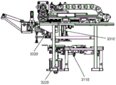
The invention provides a packaging paper box forming device, which comprises a folding edge-covering edge-pressing device 3000, a surrounding frame forming device 4000, a sticker gluing and grabbing device 5000, a short edge-folding edge-scraping edge-pressing device 6000 and a multi-station turntable 7000;
the folding edge covering and edge pressing device 3000 comprises a first folding edge component 3100 for folding the surface paper 1100 attached to the surface of the paperboard 1000, a folding edge component 3200 for attaching the folded surface paper 1100 to the paperboard 1000 and an edge pressing component 3300 for reinforcing the surface paper 1100 attached to the paperboard 1000 at the folding edge;
the surrounding frame forming device 4000 is used for folding and forming the paper board 1000 processed by the edge folding, edge covering and edge pressing device 3000;
the sticker adhesive grabbing device 5000 is used for attaching top surface paper to the top surface of the paper board 1000 after the enclosure frame is formed;
the short folding edge and edge scraping device 6000 is used for folding and scraping edges of the top facial tissue;
the periphery of the multi-station turntable 7000 is provided with a second flanging component 7100 for flanging and edging the surface paper attached to the surface of the paperboard 1000 after the surrounding frame is formed, a bottom-attaching clamp component 7200 for attaching a bottom clamp to complete the forming of the packaging box, a bubble removing component 7300 for removing bubbles from the formed packaging box, and at least three workpiece trays 7001 for bearing workpieces.
In specific implementation, as shown in fig. 1, 9, 10, 13, 21 and 22, the forming apparatus for packaging cartons comprises a folding, edge-covering and edge-pressing device 3000, a frame forming device 4000, a sticker gluing and grabbing device 5000, a folding and short edge-scraping and edge-pressing device 6000 and a multi-station turntable 7000;
as shown in fig. 2, the paperboard 1000 adhered with facial tissue 1100 is hereinafter referred to as a semi-finished paperboard, wherein two sides of the facial tissue 1100 are divided into a facial tissue long side 1110 and a facial tissue short side 1120, the paperboard 1000 is provided with a crease 1130, and the position of the crease 1130 is the edge formed by the surrounding frame;
firstly, after the paperboard 1000 is adhered with the facial tissue 1000 in the previous working section, the semi-finished paperboard is conveyed to a working position where a folding edge-wrapping and edge-pressing device 3000 is located by a conveying module, the facial tissue 1100 attached to the paperboard 1000 is turned upwards through the folding edge-wrapping and edge-pressing device 3000, then, the long edge 1110 of the facial tissue, which is turned upwards, is turned towards the inner side of the paperboard 1000 again and attached to the surface of the paperboard 1000, and the long edge 1110 of the facial tissue is completely adhered to the inner surface of the paperboard 1000 due to the fact that the surface of the facial tissue 1100 is coated with glue; then, the paperboard 1000 attached with the long side 1110 of the face paper is subjected to edge pressing;
then, after the corrugation pressing is finished, the semi-finished paperboard is turned over along the crease 1130 through a frame enclosing forming device 4000 and is formed in a frame enclosing mode; at this time, only 3 surfaces of the semi-finished paperboard enclosing frame are adhered with the facial tissue 1100, the facial tissue 1000 is not adhered to the top surface of the semi-finished paperboard enclosing frame, and the facial tissue at the top needs to be adhered to the top surface of the semi-finished paperboard enclosing frame through the facial tissue adhesive grabbing device 5000;
then, folding and edge scraping are carried out on the facial tissue short edge 1120 of the top facial tissue through a short edge folding and edge scraping device 6000;
the semi-finished paperboard before entering the multi-station turntable 7000 can be a semi-finished paperboard as shown in fig. 3, wherein in the attached facial tissue 1100, the long edges 1110 of the facial tissue on three sides are also completely attached to the inner wall of the paperboard 1000, while the short edges 1120 of the facial tissue are in a state of being turned inwards by 90 degrees, and only the long edges 1110 of the facial tissue on the remaining side are not attached to the inner wall of the paperboard 1000;
finally, the semi-finished product carton is transferred to a workpiece tray 7001 at a corresponding station of the multi-station turntable 7000, and the long edge 1110 of the facial tissue at the remaining side of the semi-finished product carton is folded inwards and covered by a second folding component 7100, so that the top facial tissue is attached to the inner wall of the paper board 1000; then the bottom card is put into the semi-finished product paper box through the bottom card sticking assembly 7200 to complete adhesion, so that the bottom card becomes the bottom of the semi-finished product paper box; finally, bubbles generated in the process of attaching the face paper 1100 are removed through the bubble removing assembly 7300, and a square packaging box without a cover is obtained.
As a preferred scheme, the second folding assembly 7100 comprises a positioning mechanism for positioning the semi-finished product carton, a flat folding mechanism for folding the attached top surface paper flatly, a folding attachment mechanism for folding the folded top surface paper and attaching the folded top surface paper to the inner surface of the paperboard 1000, and a folding driving mechanism for driving the movement of the paperboard positioning mechanism, the flat folding mechanism and the folding attachment mechanism;
during specific implementation, incoming materials of the front section are arranged regularly through the positioning mechanism, so that folding is conveniently implemented, then, sequentially through the flat folding mechanism, the long edge 1110 of the face paper on the remaining side is folded into the box by 90 degrees from the paper surface parallel to the adhered side, so that the long edge 1110 of the face paper is perpendicular to the paper board 1000, and through the folding attachment mechanism, the long edge 1110 of the face paper is folded into the box by 90 degrees and is firmly adhered to the inner surface of the corresponding paper board 1000 through extrusion.
According to the invention, by arranging the folding edge-covering edge-pressing device, the surrounding frame forming device, the sticker gluing grabbing device, the short edge-folding edge-scraping device and the multi-station turntable, a plurality of processes such as folding edge, covering edge, edge-pressing, surrounding frame, bottom card pasting, bubble removing and the like are integrated on the same equipment, so that the folding edge adhesion, the attaching effect and the surrounding frame forming effect of the facial tissue of the packaging box can be effectively improved; the whole full automation process does not need manual operation, saves the labor cost and greatly improves the production efficiency of the packaging box.
Preferably, a magnet mounting assembly 2000 for mounting a magnet on the cardboard 1000 before being processed by the hemming and edge-pressing apparatus 3000 is further included, and the magnet mounting assembly 2000 includes a four-axis mechanical gripper 2100 for gripping and mounting a magnet and a magnet mounting driving mechanism 2200 for driving the four-axis mechanical gripper 2100.
In specific implementation, as shown in fig. 4 and 5, since the side of the packing box needs to be provided with a magnet to adapt to the box cover to be opened and closed by the magnet, a magnet placing hole 1001 is further formed in the paper board 1000;
before the flanging, edge-covering and edge-pressing device 3000 processes, the semi-finished paperboard is moved to a station of the magnet mounting assembly 2000, the four-axis mechanical gripper 2100 is controlled by the magnet mounting driving mechanism 2200 to obtain a magnet at a magnet supply station and place the magnet on the magnet placement hole 1001, and after the magnet placement operation is completed, the semi-finished paperboard is transferred to a station or an intermediate station of the next process.
As a preferred scheme, the bottom of the magnet installation station is provided with an adsorption hole, and a semi-finished paperboard is fixed through an air suction assembly;
furthermore, the magnet supply position is provided with a magnet pushing assembly 2400 for pushing out the magnet from the material storage position, so that the grabbing device can grab the magnet.
In order to realize the fast circulation of products, the semi-finished paperboard is generally conveyed to a magnet installation station through a conveying belt, a photoelectric detection device 2300 can be arranged at the front end and/or the tail end of the magnet installation station, and when the semi-finished paperboard reaches the position of the photoelectric detection device 2300, the conveying belt stops running, so that the magnet installation accuracy is further improved, and the four-axis mechanical gripper 2100 is convenient to position and place magnets.
Preferably, the first folding member 3100 comprises a folding station 3110, and the folding station 3110 is a groove structure having a width corresponding to the width of the paper board 1000, and the paper board 1000 with the facial tissue 1100 attached thereto is placed in the groove structure, so that the facial tissue 1100 attached to the surface of the paper board 1000 is folded upwards.
In specific implementation, as shown in fig. 6, 7, 8 and 9, the semi-finished cardboard is conveyed to the hemming station 3110 of the first hemming assembly 3100 through the conveying module, the hemming station 3110 is a groove structure, and the width of the groove structure is matched with the width of the cardboard 1000, so that when the semi-finished cardboard is placed in the hemming station 3110, the face paper 1100 with two sides wider than the width of the cardboard 1000 is affected by the side walls of the groove structure, so that the face paper edge 1110 and the face paper short edge 1120 are folded upwards, and the hemming of the face paper 1100 is realized.
Preferably, the hemming assembly 3200 includes a hemming blade 3210 and a hemming drive mechanism 3220 for controlling the movement of the hemming blade 3210.
In specific implementation, as shown in fig. 6, 7, 8 and 9, the edge covering assembly 3200 includes an edge covering shovel 3210 and an edge covering driving mechanism 3220, the edge covering driving mechanism 3220 includes a driving cylinder having an output end connected to the edge covering shovel 3210, the edge covering shovel 3210 may be a side wall forming a groove structure of the edge folding station 3110 and located on one side of the long side 1110 of the facial tissue, when the semi-finished paperboard 1000 is placed in the edge folding station 3110, the facial tissue 1100 is folded upwards, and the driving cylinder pushes the edge covering shovel 3210 to move towards the inner side of the paperboard 1000, so that the long side 1110 of the facial tissue is folded towards the inner side of the paperboard 1000 and the paperboard is attached to the surface 1000, thereby achieving edge covering.
Preferably, the corrugating assembly 3300 includes a corrugating group 3310, and a corrugating drive mechanism 3320 for controlling movement of the corrugating group 3310.
In specific implementation, as shown in fig. 6, 7, 8 and 9, the corrugating unit 3300 includes a corrugating bar set 3310 and a corrugating driving mechanism 3320, the corrugating bar set 3310 is used to reinforce the adhesion of the paper 1100 to the board 1000 at the fold 1130, and the corrugating driving mechanism 3320 is used to drive the corrugating bar set 3310 to move downward to corrugate the board 1000, and after the corrugating bar set 3310 is controlled to return to the initial position to wait for the next product, the process is repeated.
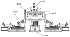
Preferably, the frame surrounding forming device 4000 comprises a bottom surface jacking assembly 4100, a side folding assembly 4200, a top surface turning plate assembly 4300 and a mould assembly 4400;
the side flanging assemblies 4200 are symmetrically arranged on the left side and the right side of the bottom surface jacking assembly 4100 and can rotate relative to the bottom surface jacking assembly 4100; the top surface turning plate component 4300 is arranged above the bottom surface jacking component 4100 and can rotate relative to the bottom surface jacking component 4100; a mold assembly 4400 is arranged between the bottom surface jacking assembly 4100 and the top surface turning plate assembly 4300, and the mold assembly 4400 can rotate to the position above the bottom surface jacking assembly 4100.
In specific implementation, as shown in fig. 10, 11 and 12, the corrugated cardboard 1000 has four folds 1130 to divide the cardboard 1000 into four sides, i.e., a bottom side, two side faces and a top side, which surround the frame; transferring the semi-finished corrugated paperboard to a turning frame station through a carrying module, and specifically, positioning the semi-finished corrugated paperboard on a supporting surface formed by a bottom surface jacking assembly 4100 and a side folding assembly 4200, wherein the bottom surface is positioned on the bottom surface jacking assembly 4100, two side surfaces are respectively positioned on the side folding assemblies 4200, and the top surface is positioned on one side folding assembly 4200;
the die assembly 4400 rotates to the position above the bottom surface jacking assembly 4100; then the bottom surface jacking assembly 4100 is lifted, and is matched with the die assembly 4400 to press and clamp the bottom surface, meanwhile, the side surface folding edge assemblies 4200 symmetrically arranged at the left side and the right side of the bottom surface jacking assembly 4100 can rotate 90 degrees from the horizontal direction to the die assembly 4400 relative to the bottom surface jacking assembly 4100, and the other two side surfaces of the paperboard are folded around the folding mark 1130 to be vertical to the bottom surface of the paperboard 1000, so that the two side surfaces of the paperboard 1000 are attached to the two vertical edges of the die assembly 4400;
when the side edge of the enclosure frame is formed, the top surface of the paperboard 1000 is naturally turned over towards the inside of the enclosure frame from the vertical direction because the inner side of the paperboard is subjected to edge pressing; the top surface turnover plate assembly 4300 and the bottom surface jacking assembly 4100 of the top surface turnover plate assembly 4300 are rotated by 90 degrees from the vertical direction to the mold assembly 4400 to the horizontal direction, and are matched with the mold assembly 4400 to press and clamp the top surface of the paperboard 1000, so that the semi-finished paperboard is automatically formed in a surrounding frame mode.
The bottom surface jacking assembly 4100, the side flanging assembly 4200, the top surface turning plate assembly 4300 and the die assembly 4400 are matched to form the semi-finished paperboard enclosing frame, and the manufactured enclosing frame is good in consistency, high in automation degree and production efficiency and suitable for large-scale production and application.
Specifically, the size of the mold assembly 4400 is matched with the shape and the size of the semi-finished paperboard enclosing frame, the mold assembly 4400 is a three-dimensional square block which has the same inner shape with the semi-finished paperboard enclosing frame, and the paperboard 1000 encloses a rectangular frame along the outer surface of the mold assembly 4400.
When in use, the mold assembly 4400 can be replaced by a person skilled in the art according to the requirement; the mold assembly 4400 can be rotated above the bottom jacking assembly 4100, and the mold assembly 4400 can be connected with an existing rotating mechanism, so that the mold assembly 4400 can rotate.
Preferably, the side gusset assembly 4200 includes a side enclosure plate 4251 for placing the sheet 1000 and a rotary drive mechanism.
In specific implementation, as shown in fig. 10, 11, and 12, before the step of forming the semi-finished cardboard enclosure frame, the side enclosure frame plate 4251 is placed in the horizontal direction, and when the step of forming the cardboard enclosure frame is performed, the semi-finished cardboard is transferred to the station where the enclosure frame forming device 4000 is located, the bottom jacking component 4100 is lifted to push against the bottom surface of the cardboard 1000, the cardboard 1000 is clamped and fixed by matching with the mold assembly 4400, the side enclosure frame plate 4251 is driven by the rotary driving mechanism to rotate from the horizontal position to the vertical position, two side surfaces of the cardboard 1000 are attached along two vertical edges of the mold assembly 4400, and side forming is completed.
Preferably, the upper end of the side enclosing frame plate 4251 is provided with a folding enclosing plate assembly 4260; the folding fence assembly 4260 comprises a folding fence 4261 and a 90-degree rotating mechanism, so that the 90-degree rotating mechanism drives the folding fence 4261 to rotate 90 degrees.
In specific implementation, as shown in fig. 10, 11 and 12, the folding fence assembly 4260 of the present embodiment is designed to enable the folding fence 4261 at the upper end of the side surrounding frame plate 4251 to rotate 90 degrees from the vertical direction towards the inside of the surrounding frame, so as to further ensure that the top surface of the cardboard 1000 is folded and falls down from the vertical direction towards the inside of the surrounding frame.
Specifically, the folding fence assembly 4260 is arranged at the upper end of one of the two bilaterally symmetrically arranged side fence plates 4251, and the specific position is selected according to the position of the top surface of the paperboard 1000.
The folding fence assembly 4260 comprises a folding fence 4261 and a 90-degree rotating mechanism, and the 90-degree rotating mechanism may adopt an existing mechanism, such as a 90-degree rotating link mechanism, a pneumatic rotating cylinder, a rack-and-pinion 90-degree rotating mechanism or a crank rocker mechanism, so that the 90-degree rotating mechanism drives the folding fence 4261 to rotate 90 degrees.
Preferably, the bottom surface jacking assembly 4100 comprises a bottom surface fixing plate 4110 and a movable lifting mechanism 4120 for jacking the bottom surface fixing plate 4110.
In a specific implementation, as shown in fig. 10, 11 and 12, the bottom surface fixing plate 4110 is used for cooperating with the mold assembly 4400 to fix the bottom surface of the paper board 1000 on the bottom surface fixing plate 4110, so as to facilitate a subsequent side frame; the movable lifting mechanism 4120 is connected to the bottom surface fixing plate 4110 such that the movable lifting mechanism 4120 drives the bottom surface fixing plate 4110 to move up and down, and the movable lifting mechanism 4120 may adopt an existing reciprocating linear motion mechanism.
Preferably, the sticker gluing and grabbing device 5000 comprises a frame 5100, a storage mechanism 5200 arranged on the frame 5100 and used for placing top surface paper, a carrying mechanism 5300 arranged above the storage mechanism 5200 and used for conveying the top surface paper in the storage mechanism 5200 outwards, a grabbing mechanism 5400 used for grabbing the top surface paper and attaching the glued top surface paper to the top surface of the cardboard 1000 after the enclosing frame is formed, and a gluing mechanism 5500 arranged below the grabbing mechanism 5400 and used for gluing the top surface paper.
In specific implementation, as shown in fig. 13, 14 and 15, a storage mechanism 5200 is arranged inside the frame 5100, before work, top tissue needs to be filled into the storage mechanism 5200, and then the top tissue is automatically conveyed from the storage mechanism 5200 to a designated position by a conveying mechanism 5300 for being gripped by the gripping mechanism 5400; the grabbing mechanism 5400 receives the top surface paper output by the carrying mechanism 5300, conveys the top surface paper to the glue coating mechanism 5500 positioned below the grabbing mechanism 5400, and after the top surface paper is coated with glue, the glued top surface paper is attached to the top surface of the paper board 1000 after the enclosure frame is formed through the grabbing mechanism 5400.
Preferably, the storage mechanism 5200 is provided with a lifting device 5210 inside for lifting the top surface paper.
In specific implementation, as shown in fig. 14, a lifting device 5210 capable of lifting the top surface paper is arranged inside the storage mechanism 5200. Preferably, the lifting device 5210 can lift the material to the top of the storage mechanism 5200 by a manual driving screw, a motor-driven guide rail or an air bar driving lifting, and wait for the carrying mechanism 5300 to transport the top facial tissue.
Preferably, the gluing mechanism 5500 includes a gluing frame 5510, the gluing frame 5510 is provided with a roller assembly 5520, a driving device 5530 for driving the roller assembly 5520, and a glue tray 5540 placed below the roller assembly 5520 for dipping glue on the roller assembly 5520.
In specific implementation, as shown in fig. 16, 17 and 18, the glue spreading mechanism 5500 includes a glue spreading frame 5510, and the glue spreading frame 5510 is provided with a roller assembly 5520, a driving device 5530 for driving the roller assembly 5520, and a glue containing tray 5540 placed below the roller assembly 5520 and used for dipping glue on the roller assembly 5520. Before working, glue is injected into the glue containing tray 5540 manually or through a glue adding pipe; when the automatic gluing device works, the lower circumferential surface of the roller assembly 5520 is soaked in glue in the glue containing tray 5540, the roller assembly 5520 is driven by the driving device 5530 to rotate, so that the glue is uniformly stained on the outer circumferential surface of the roller assembly 5520, when the grabbing mechanism 5400 drives the top face paper to pass through the highest position of the roller assembly 5520, the glue is smeared, and the purpose of automatically gluing the top face paper is achieved. As a preferable scheme, the roller assembly 5520 may adopt a form that an upper roller tube and a lower roller tube are close to each other, and the size of the smearing amount of glue is controlled by adjusting the distance of the central axis of the two roller tubes. On the other hand still is provided with stop device near the outer peripheral surface of an upper roller section of thick bamboo in the frame, dips in the glue after full in the institute week of a running roller section of thick bamboo, can keep off unnecessary glue when stop device, can make a section of thick bamboo of applying glue more even on the top facial tissue.
Preferably, the glue spreading mechanism 5500 further includes a support tray 5550 disposed below the glue containing tray 5540 and a driving assembly 5560 for driving the support tray 5550 to move up and down.
In specific implementation, as shown in fig. 17 and 18, the glue spreading mechanism 5500 further includes a support tray 5550 disposed below the glue containing tray 5540 and a driving unit 5560 for driving the support tray 5550 to move up and down. The supporting tray 5550 is used for supporting the glue containing tray 5540, when the driving assembly 5560 drives the supporting tray 5550 to move downwards, the glue containing tray 5540 also moves downwards along with the downward movement, and the function of the supporting tray 5550 is that the glue containing tray 5540 can be taken out of the gluing mechanism 5500, so that the glue containing tray can be conveniently filled with glue or cleaned; when the glue spreader works, the driving component 5560 drives the supporting tray 5550 to move upwards, and the glue containing tray 5540 also moves upwards along with the supporting tray, and the supporting tray moves to a position where the roller barrel can dip glue on the roller barrel. Preferably, the driving assembly 5560 may employ a cylinder as a power source.
Preferably, the short folding edge scraping and corrugating device 6000 comprises a supporting mold assembly 6100 for supporting the inside of the frame back paper board 1000, a short folding edge assembly 6200 for folding the top facial paper short edges 1120, and a corrugating edge scraping assembly 6300 for scraping the folded facial paper short edges 1120.
In specific implementation, as shown in fig. 19, 20 and 21, the folding edge assembly 6100 is a workpiece with right-angle edges, and the supporting mold 6300 is a three-dimensional square block having the same shape as the inner shape of the semi-finished cardboard enclosure;
firstly, the paperboard 1000 processed by the sticker gluing and grabbing device 5000 is transported to a station of the short-folding edge and edge scraping device 6000 through a carrying module, and a supporting die 6300 extends into the interior of the surrounding frame of the paperboard 1000 to support the paperboard 1000; the folding edge assembly 6100 located above the paper board 1000 presses the paper board 1000 after the enclosure frame is formed downward, so that the facial tissue short edge 1120 of the facial tissue at the top of the paper board is folded downward by 90 degrees; then the front corrugating unit 6200 presses the facial tissue short edge 1120 and moves horizontally back and forth to achieve the corrugating effect;
the cardboard 1000 after being processed by the short edge folding and edge scraping device 6000 is a semi-finished cardboard as shown in fig. 3, in the attached facial tissue 1100, the long edges 1110 of the facial tissue on three sides are also attached to the inner wall of the cardboard 1000, the short edges 1120 of the facial tissue on four sides are all in a state of being turned inwards by 90 degrees, and only the long edges 1110 of the facial tissue on the remaining one side are not attached to the inner wall of the cardboard 1000, and then the cardboard is transported to the next process through a transporting module.
Preferably, the multi-station turntable 7000 further comprises a turning feeding assembly 7400 for conveying the paper board 1000 after the enclosing frame is formed to the workpiece tray 7001, a blanking assembly 7500 for conveying the packaging boxes out of the multi-station turntable 7000, and a gluing assembly 7600 for spraying glue on the surface of the bottom plate after the bottom plate adhering operation is completed.
In specific implementation, as shown in fig. 23 and 24, the turning and feeding assembly 7400 includes a cardboard feeding clamping jaw 7410, the cardboard feeding clamping jaw 7410 can more stably grab and transfer the semi-finished cardboard to the workpiece tray 7001, the number of the cardboard feeding clamping jaws 7410 is preferably 4, stable product transfer is realized by simultaneously clamping four corners of the semi-finished cardboard, a cardboard feeding driving mechanism 7420 is disposed above the cardboard feeding clamping jaw 7410 through a bracket, the cardboard feeding driving mechanism 7420 includes a servo motor for driving the cardboard feeding clamping jaw 7410 to reciprocate between the cardboard supplying process and the multi-station turntable 7000, and an air cylinder for driving the cardboard feeding clamping jaw 7410 to move up and down, in actual operation, the cardboard clamping jaws 7410 are distributed on two sides, the clamping jaws are controlled to be close to clamp, so that the paper board is carried to move, and the paper board is transferred into the workpiece tray 7001;
as an adaptive solution, as shown in fig. 23 and fig. 24, the turning and feeding assembly 7400 may further be provided with a turning mechanism 7430, where the turning mechanism 7430 is used to turn the semi-finished paperboard conveyed in the previous step, and convey the turned semi-finished paperboard to the workpiece tray 7001 through the paperboard feeding clamping jaws 7410, on one hand, the paperboard feeding clamping jaws 7410 can be conveniently clamped by turning, and on the other hand, the product is turned, so as to conveniently implement the subsequent steps.
Specifically, as shown in fig. 25, unloading subassembly 7500 includes unloading sucking disc 7510, adsorbs the packing carton that has attached the end card through unloading sucking disc 7510 to shift it to the discharge gate, unloading sucking disc 7510 preferably sets up to 4, through carrying out the mode that adsorbs the product in four corners simultaneously for the more stable quilt of product is conveyed to the discharge gate, unloading actuating mechanism 7520 is including being used for driving unloading sucking disc 7510 and the servo motor of reciprocating motion between carousel 7000 and subsequent handling to and be used for driving the cylinder of unloading sucking disc 7510 up-and-down motion, and when using in practice, absorb the product through cylinder control sucking disc to realize portability packing carton motion, with the realization with the packing carton transport work piece tray 7001.
Specifically, in order to fully utilize the space and the operation advantages of the multi-station turntable 7000, as shown in fig. 22 and 26, a gluing assembly 7600 is further disposed around the multi-station turntable 7000, the gluing assembly 7600 is used for gluing the surface of the bottom plate of the packaging box after the bottom plate adhering operation is completed, the gluing mode can be glue spraying, glue dispensing and the like, and the gluing process is a pre-process for facilitating the subsequent process to adhere the decorative bottom plate inside the packaging box.
Preferably, the bottom card attaching assembly 7200 comprises a bottom card positioning mechanism 7210, a bottom card feeding suction cup 7220, and a bottom card feeding driving mechanism 7230 for driving the bottom card feeding suction cup 7220 to move;
the bottom card positioning mechanism 7210 includes a positioning push plate 7211 and a positioning fixing plate 7212, the positioning push plate 7211 is moved by the pushing of an air cylinder.
In specific implementation, as shown in fig. 27 and 29, the bottom card attaching assembly 7200 includes a bottom card positioning mechanism 7210, the bottom card positioning mechanism 7210 includes a positioning push plate 7211 and a positioning fixing plate 7212, and the positioning push plate 7211 disposed on the other three sides is matched with the positioning fixing plate 7212 to position the position of the bottom card conveyed to the bottom card positioning mechanism 7210, so that the bottom card feeding suction cup 7220 can be more accurately placed on a paper board formed by an inner frame of the workpiece tray 7001 when sucking the bottom card and transferring the bottom card, thereby reducing multiple operations or defective products caused by inaccurate placement;
wherein, end card material loading actuating mechanism 7230 is including being used for driving end card material loading sucking disc 7220 at multistation carousel 7000 and end card positioning mechanism 7210 reciprocating motion's servo motor to and be used for driving end card material loading sucking disc 7220 oscilaltion motion's cylinder, when in actual use, absorb the product through cylinder control sucking disc, thereby realize the motion of portability end card, in order to realize carrying out end card positioning mechanism 7210 with the end card and place the product on work piece tray 7001.
Preferably, the defoaming assembly 7300 includes a defoaming die 7310 located above the work tray 7001, and a defoaming driving mechanism 7320 for driving the defoaming die 7310 to move up and down.
In specific implementation, as shown in fig. 29 and 30, the defoaming assembly 7300 is used for defoaming the surface paper attached to the surface of the packaging box, the defoaming assembly 7300 includes a defoaming die 7310 and a defoaming driving mechanism 7320, the defoaming driving mechanism 7320 is disposed above the multi-station turntable 7000 through a bracket, the defoaming die 7310 is connected with the output end of the defoaming driving mechanism 7320, the defoaming die 7310 is a cuboid as a whole, the size of the defoaming die 7310 is matched with the size inside the packaging box, preferably, the defoaming driving mechanism 7320 is an air cylinder, the defoaming die 7310 is made of POM material, and the defoaming die 7310 can be driven to move up and down when the defoaming driving mechanism 7320 operates.
Preferably, the defoaming assembly 7300 further includes a movable top block 7330 disposed below the multi-station turntable 7000, and a movable top block driving mechanism 7340 for controlling the movable top block 7330 to push the bottom surface of the workpiece tray 7001 upward to cooperate with a defoaming die 7310 to extrude and defoam the product on the workpiece tray 7001.
In specific implementation, as shown in fig. 29 and fig. 30, the defoaming assembly 7300 further includes a movable top block 7330, the movable top block driving mechanism 7340 is a double-stroke cylinder, and the movable top block driving mechanism 7330 is controlled to move upwards, and contacts with the bottom surface of the workpiece tray 7001 after passing through the multi-station turntable 7000, and continues to push upwards, so as to realize the re-extrusion defoaming of the product by matching with the defoaming mold 7310, thereby further enhancing the defoaming effect;
as a preferable scheme, as shown in fig. 29 and fig. 30, the defoaming assembly 7300 includes a fixed platform 7350, a through hole is formed in the fixed platform 7350 for the up-and-down movement of the movable top block 7330, meanwhile, 2 positioning protrusions 7351 are provided on the fixed platform 7350, pushing cylinders 7352 are respectively provided at the left and right sides below the fixed platform 7350, the positioning protrusions 7351 are adapted to the positioning grooves provided below the turntable 7000, in a specific implementation, the two-stroke cylinder and the pushing cylinders 7352 are simultaneously activated, the pushing cylinders 7352 push the fixed platform 7350 to move upward so that the positioning protrusions 7351 extend into the positioning grooves, so that the fixed platform 7350 can be aligned with the workpiece tray 7001, and the two-stroke cylinder continues to push the movable top block 7330 to push the bottom plate of the workpiece tray 7001 upward for secondary extrusion defoaming.
Although terms such as cardboard, facial tissue, magnet mounting assemblies, hemming and edge folding and pressing devices, framing devices, short-edge folding and edge scraping devices, multi-station turntables, etc. are used more often herein, the possibility of using other terms is not excluded. These terms are used merely to more conveniently describe and explain the nature of the present invention; they are to be construed as being without limitation to any additional limitations that may be imposed by the spirit of the present invention.
Finally, it should be noted that: the above embodiments are only used to illustrate the technical solution of the present invention, and not to limit the same; while the invention has been described in detail and with reference to the foregoing embodiments, it will be understood by those skilled in the art that: the technical solutions described in the foregoing embodiments may still be modified, or some or all of the technical features may be equivalently replaced; and the modifications or the substitutions do not make the essence of the corresponding technical solutions depart from the scope of the technical solutions of the embodiments of the present invention.
Claims (10)
1. A packaging carton forming device is characterized in that: comprises a folding edge-covering and edge-pressing device (3000), a surrounding frame forming device (4000), a sticker gluing and grabbing device (5000), a short edge-folding edge-scraping and edge-pressing device (6000) and a multi-station turntable (7000);
the flanging, edge-covering and edge-pressing device (3000) comprises a first flanging assembly (3100) for flanging the surface paper (1100) attached to the surface of the paperboard (1000), a flanging assembly (3200) for attaching the flanged surface paper (1100) to the paperboard (1000), and an edge-pressing assembly (3300) for reinforcing the surface paper (1100) at the position of the crease and attaching to the paperboard (1000);
the surrounding frame forming device (4000) is used for turning and forming the folding and surrounding frame of the paperboard (1000) processed by the folding, edge-wrapping and edge-pressing device (3000);
the sticker gluing and grabbing device (5000) is used for attaching top surface paper to the top surface of the paper board (1000) after the enclosure frame is formed;
the folding edge and edge scraping device (6000) is used for folding and scraping edges of the top facial tissue;
the periphery of the multi-station turntable (7000) is provided with a second folding edge assembly (7100) for folding and edge-wrapping the surface paper attached to the surface of the paper board (1000) after the surrounding frame is formed, a bottom-attaching clamp assembly (7200) for attaching a bottom clamp to complete forming of the packaging box, a bubble removing assembly (7300) for removing bubbles from the formed packaging box and at least three workpiece trays (7001) for bearing workpieces.
2. The packaging carton forming apparatus as claimed in claim 1, wherein: the first edge folding assembly (3100) comprises an edge folding station (3110), the edge folding station (3110) is a groove structure with the width matched with that of the paper board (1000), and the paper board (1000) attached with the surface paper (1100) is placed into the groove structure, so that the surface paper (1100) attached to the surface of the paper board (1000) is folded upwards.
3. The packaging carton forming apparatus as claimed in claim 1, wherein: the edge covering assembly (3200) comprises an edge covering shovel plate (3210) and an edge covering driving mechanism (3220) for controlling the movement of the edge covering shovel plate (3210).
4. The packaging carton forming apparatus as claimed in claim 1, wherein: the corrugating component (3300) comprises a corrugating strip group (3310) and a corrugating driving mechanism (3320) for controlling the movement of the corrugating strip group (3310).
5. The packaging carton forming apparatus as claimed in claim 1, wherein: the enclosure frame forming device (4000) comprises a bottom surface jacking assembly (4100), a side flanging assembly (4200), a top surface turning plate assembly (4300) and a mould assembly (4400);
the side flanging assemblies (4200) are symmetrically arranged on the left side and the right side of the bottom surface jacking assembly (4100) and can rotate relative to the bottom surface jacking assembly (4100); the top surface turning plate component (4300) is arranged above the bottom surface jacking component (4100) and can rotate relative to the bottom surface jacking component (4100); be equipped with mould subassembly (4400) between bottom surface jacking subassembly (4100) and top surface flap subassembly (4300), mould subassembly (4400) can rotate to the top of bottom surface jacking subassembly (4100).
6. The packaging carton forming apparatus as claimed in claim 1, wherein: the sticker gluing and grabbing device (5000) comprises a rack (5100), a storage mechanism (5200) arranged on the rack (5100) and used for placing top surface paper, a carrying mechanism (5300) used for outwards conveying the top surface paper in the storage mechanism (5200), a grabbing mechanism (5400) used for grabbing the top surface paper and attaching the glued top surface paper to the top surface of a paperboard (1000) after a surrounding frame is formed, and a gluing mechanism (5500) used for gluing the top surface paper.
7. The packaging carton forming apparatus as claimed in claim 1, wherein: folding the weak point and scraping stupefied limit device (6000) including be used for to enclosing frame back cardboard (1000) inside support mould subassembly (6100) that support, be used for turning over a facial tissue minor face (1120) of top facial tissue and roll over weak point subassembly (6200) and be used for scraping stupefied limit subassembly (6300) to facial tissue minor face (1120) after turning over.
8. The packaging carton forming apparatus as claimed in claim 1, wherein: the multi-station turntable (7000) further comprises a turnover feeding assembly (7400) used for conveying the paper board (1000) after the enclosing frame is formed to the workpiece tray (7001), a discharging assembly (7500) used for conveying out the packaging boxes of the multi-station turntable (7000) and a gluing assembly (7600) used for spraying glue on the surface of the bottom plate after the bottom plate adhering operation is completed.
9. The packaging carton forming apparatus as claimed in claim 1, wherein: the defoaming assembly (7300) comprises a defoaming die (7310) positioned above the workpiece tray (7001), and a defoaming driving mechanism (7320) for driving the defoaming die (7310) to move up and down.
10. The packaging carton forming apparatus as claimed in claim 1, wherein: the bottom card sticking assembly (7200) comprises a bottom card positioning mechanism (7210), a bottom card feeding suction cup (7220) and a bottom card feeding driving mechanism (7230) for driving the bottom card feeding suction cup (7220) to move;
the bottom card positioning mechanism (7210) comprises a positioning push plate (7211) and a positioning fixing plate (7212), and the positioning push plate (7211) is pushed to move by an air cylinder.
Priority Applications (1)
| Application Number | Priority Date | Filing Date | Title |
|---|---|---|---|
| CN202011337574.XA CN112339335A (en) | 2020-11-25 | 2020-11-25 | Packaging carton forming equipment |
Applications Claiming Priority (1)
| Application Number | Priority Date | Filing Date | Title |
|---|---|---|---|
| CN202011337574.XA CN112339335A (en) | 2020-11-25 | 2020-11-25 | Packaging carton forming equipment |
Publications (1)
| Publication Number | Publication Date |
|---|---|
| CN112339335A true CN112339335A (en) | 2021-02-09 |
Family
ID=74365524
Family Applications (1)
| Application Number | Title | Priority Date | Filing Date |
|---|---|---|---|
| CN202011337574.XA Pending CN112339335A (en) | 2020-11-25 | 2020-11-25 | Packaging carton forming equipment |
Country Status (1)
| Country | Link |
|---|---|
| CN (1) | CN112339335A (en) |
Cited By (9)
| Publication number | Priority date | Publication date | Assignee | Title |
|---|---|---|---|---|
| CN113147083A (en) * | 2021-05-12 | 2021-07-23 | 许昌裕同印刷包装有限公司 | Enclose frame make-up machine |
| CN113276473A (en) * | 2021-05-17 | 2021-08-20 | 武汉嘉艺华颂技术有限公司 | Box encloses frame shaping structure in packing |
| CN113580658A (en) * | 2021-07-30 | 2021-11-02 | 漳州鑫圣源包装制品有限公司 | Corrugated box automated production assembly line |
| CN114083829A (en) * | 2021-11-26 | 2022-02-25 | 中科天工(武汉)智能技术有限公司 | Method and device for folding edges of gummed paper material |
| CN114228237A (en) * | 2021-11-18 | 2022-03-25 | 金华瑞彬智能制造科技有限公司 | Full-automatic cake box bottom support production equipment and processing method thereof |
| CN114589960A (en) * | 2022-05-05 | 2022-06-07 | 苏州裕同印刷有限公司 | Automatic hem shaping assembly line |
| CN114633514A (en) * | 2022-03-17 | 2022-06-17 | 广东力顺源智能自动化有限公司 | Automatic bending and edge covering machine core of paperboard |
| CN115610014A (en) * | 2022-10-27 | 2023-01-17 | 湖北京华彩印有限公司 | Edge covering forming method for manual packaging box surrounding frame |
| CN117416095A (en) * | 2023-12-19 | 2024-01-19 | 苏州裕同印刷有限公司 | Box sleeve forming equipment and forming method |
-
2020
- 2020-11-25 CN CN202011337574.XA patent/CN112339335A/en active Pending
Cited By (14)
| Publication number | Priority date | Publication date | Assignee | Title |
|---|---|---|---|---|
| CN113147083B (en) * | 2021-05-12 | 2023-02-03 | 许昌裕同印刷包装有限公司 | Enclose frame make-up machine |
| CN113147083A (en) * | 2021-05-12 | 2021-07-23 | 许昌裕同印刷包装有限公司 | Enclose frame make-up machine |
| CN113276473A (en) * | 2021-05-17 | 2021-08-20 | 武汉嘉艺华颂技术有限公司 | Box encloses frame shaping structure in packing |
| CN113580658A (en) * | 2021-07-30 | 2021-11-02 | 漳州鑫圣源包装制品有限公司 | Corrugated box automated production assembly line |
| CN113580658B (en) * | 2021-07-30 | 2023-09-26 | 陕西吉宏包装有限公司 | Automatic production line for corrugated cartons |
| CN114228237B (en) * | 2021-11-18 | 2023-12-08 | 金华瑞彬智能制造科技有限公司 | Full-automatic cake box bottom support production equipment and processing method thereof |
| CN114228237A (en) * | 2021-11-18 | 2022-03-25 | 金华瑞彬智能制造科技有限公司 | Full-automatic cake box bottom support production equipment and processing method thereof |
| CN114083829B (en) * | 2021-11-26 | 2023-03-10 | 中科天工(武汉)智能技术有限公司 | Method and device for folding edges of gummed paper material |
| CN114083829A (en) * | 2021-11-26 | 2022-02-25 | 中科天工(武汉)智能技术有限公司 | Method and device for folding edges of gummed paper material |
| CN114633514A (en) * | 2022-03-17 | 2022-06-17 | 广东力顺源智能自动化有限公司 | Automatic bending and edge covering machine core of paperboard |
| CN114589960A (en) * | 2022-05-05 | 2022-06-07 | 苏州裕同印刷有限公司 | Automatic hem shaping assembly line |
| CN115610014A (en) * | 2022-10-27 | 2023-01-17 | 湖北京华彩印有限公司 | Edge covering forming method for manual packaging box surrounding frame |
| CN117416095A (en) * | 2023-12-19 | 2024-01-19 | 苏州裕同印刷有限公司 | Box sleeve forming equipment and forming method |
| CN117416095B (en) * | 2023-12-19 | 2024-02-20 | 苏州裕同印刷有限公司 | Box sleeve forming equipment and forming method |
Similar Documents
| Publication | Publication Date | Title |
|---|---|---|
| CN112339335A (en) | Packaging carton forming equipment | |
| CN214448853U (en) | Packaging carton forming equipment | |
| CN108466449B (en) | Inner box forming equipment and forming method of paper box | |
| CN206590158U (en) | Automatic corner protector inclusion mechanism | |
| CN214448871U (en) | Slip sheet snatchs suction disc mechanism and automatic slip sheet equipment of pasting | |
| EP3638589A1 (en) | Packing station and method for ceramic slabs | |
| CN113665874B (en) | Automatic packaging system and method for bagged products | |
| CN114633512A (en) | Automatic forming method of paper box | |
| CN213593749U (en) | Feeding mechanism of iron sheet sticking machine | |
| CN210148812U (en) | Novel paperboard indentation device | |
| CN110509604B (en) | Forming and defoaming machine for leather case packaging box and using method thereof | |
| CN214188629U (en) | Bubble removing equipment for forming of packaging box | |
| CN112078182A (en) | Automatic packaging box forming system and method | |
| CN114589960B (en) | Automatic hem shaping assembly line | |
| CN111216407A (en) | Automatic forming equipment that bordures of carton | |
| CN112223829A (en) | Bubble removing equipment for forming of packaging box | |
| CN214160262U (en) | Adhesive coating grabbing equipment for stickers | |
| CN215554778U (en) | Automatic packaging system for bagged products | |
| CN210525944U (en) | Forming and defoaming machine for leather case packaging box | |
| CN212472562U (en) | Automatic attaching and folding equipment for feeding device and packaging box | |
| CN211031427U (en) | Automatic dough wrapping machine with edge folding and bubble removing functions | |
| CN112757700A (en) | Honeycomb carton manufacturing device and method with damping function | |
| CN214164216U (en) | Edge folding, edge covering and edge pressing equipment for facial tissue of packaging box | |
| CN216610222U (en) | Fine work carton transmission loading attachment | |
| CN219505561U (en) | Dispensing forming machine |
Legal Events
| Date | Code | Title | Description |
|---|---|---|---|
| PB01 | Publication | ||
| PB01 | Publication | ||
| SE01 | Entry into force of request for substantive examination | ||
| SE01 | Entry into force of request for substantive examination |