CN216807858U - Hoisting device and hoisting equipment - Google Patents
Hoisting device and hoisting equipment Download PDFInfo
- Publication number
- CN216807858U CN216807858U CN202122509497.8U CN202122509497U CN216807858U CN 216807858 U CN216807858 U CN 216807858U CN 202122509497 U CN202122509497 U CN 202122509497U CN 216807858 U CN216807858 U CN 216807858U
- Authority
- CN
- China
- Prior art keywords
- guide
- hoisting
- hoisting device
- telescopic structure
- flexible connecting
- Prior art date
- Legal status (The legal status is an assumption and is not a legal conclusion. Google has not performed a legal analysis and makes no representation as to the accuracy of the status listed.)
- Active
Links
Images


Classifications
-
- B—PERFORMING OPERATIONS; TRANSPORTING
- B60—VEHICLES IN GENERAL
- B60L—PROPULSION OF ELECTRICALLY-PROPELLED VEHICLES; SUPPLYING ELECTRIC POWER FOR AUXILIARY EQUIPMENT OF ELECTRICALLY-PROPELLED VEHICLES; ELECTRODYNAMIC BRAKE SYSTEMS FOR VEHICLES IN GENERAL; MAGNETIC SUSPENSION OR LEVITATION FOR VEHICLES; MONITORING OPERATING VARIABLES OF ELECTRICALLY-PROPELLED VEHICLES; ELECTRIC SAFETY DEVICES FOR ELECTRICALLY-PROPELLED VEHICLES
- B60L53/00—Methods of charging batteries, specially adapted for electric vehicles; Charging stations or on-board charging equipment therefor; Exchange of energy storage elements in electric vehicles
- B60L53/80—Exchanging energy storage elements, e.g. removable batteries
-
- B—PERFORMING OPERATIONS; TRANSPORTING
- B66—HOISTING; LIFTING; HAULING
- B66C—CRANES; LOAD-ENGAGING ELEMENTS OR DEVICES FOR CRANES, CAPSTANS, WINCHES, OR TACKLES
- B66C13/00—Other constructional features or details
- B66C13/04—Auxiliary devices for controlling movements of suspended loads, or preventing cable slack
- B66C13/06—Auxiliary devices for controlling movements of suspended loads, or preventing cable slack for minimising or preventing longitudinal or transverse swinging of loads
-
- B—PERFORMING OPERATIONS; TRANSPORTING
- B66—HOISTING; LIFTING; HAULING
- B66C—CRANES; LOAD-ENGAGING ELEMENTS OR DEVICES FOR CRANES, CAPSTANS, WINCHES, OR TACKLES
- B66C17/00—Overhead travelling cranes comprising one or more substantially horizontal girders the ends of which are directly supported by wheels or rollers running on tracks carried by spaced supports
-
- Y—GENERAL TAGGING OF NEW TECHNOLOGICAL DEVELOPMENTS; GENERAL TAGGING OF CROSS-SECTIONAL TECHNOLOGIES SPANNING OVER SEVERAL SECTIONS OF THE IPC; TECHNICAL SUBJECTS COVERED BY FORMER USPC CROSS-REFERENCE ART COLLECTIONS [XRACs] AND DIGESTS
- Y02—TECHNOLOGIES OR APPLICATIONS FOR MITIGATION OR ADAPTATION AGAINST CLIMATE CHANGE
- Y02T—CLIMATE CHANGE MITIGATION TECHNOLOGIES RELATED TO TRANSPORTATION
- Y02T10/00—Road transport of goods or passengers
- Y02T10/60—Other road transportation technologies with climate change mitigation effect
- Y02T10/70—Energy storage systems for electromobility, e.g. batteries
-
- Y—GENERAL TAGGING OF NEW TECHNOLOGICAL DEVELOPMENTS; GENERAL TAGGING OF CROSS-SECTIONAL TECHNOLOGIES SPANNING OVER SEVERAL SECTIONS OF THE IPC; TECHNICAL SUBJECTS COVERED BY FORMER USPC CROSS-REFERENCE ART COLLECTIONS [XRACs] AND DIGESTS
- Y02—TECHNOLOGIES OR APPLICATIONS FOR MITIGATION OR ADAPTATION AGAINST CLIMATE CHANGE
- Y02T—CLIMATE CHANGE MITIGATION TECHNOLOGIES RELATED TO TRANSPORTATION
- Y02T10/00—Road transport of goods or passengers
- Y02T10/60—Other road transportation technologies with climate change mitigation effect
- Y02T10/7072—Electromobility specific charging systems or methods for batteries, ultracapacitors, supercapacitors or double-layer capacitors
Abstract
The hoisting device comprises a rigid telescopic mechanism (10), a flexible connecting mechanism (20), a hoisting tool (30) and a guide mechanism (40). The rigid telescopic mechanism comprises a top support (12), a telescopic structure (14), a lifter (16) and a bottom support (18). The flexible connecting mechanism is connected with the bottom support. One end of the lifting appliance is connected with the flexible connecting mechanism, and the other end of the lifting appliance can be selectively connected with an object to be lifted. The guide mechanism comprises a plurality of pairs of guide columns (42) and guide sleeves (44), the guide columns are arranged on the lifting appliance, and the guide sleeves are arranged on the jacking supports. The utility model also provides hoisting equipment using the hoisting device. The rigid telescopic mechanism of the hoisting device reduces the offset of the hoisted object in the carrying process, and the flexible connecting mechanism enables the hoisting device to be conveniently and accurately butted with the hoisted object, so that the hoisting device is particularly suitable for replacing a vehicle battery box.
Description
Technical Field
The utility model relates to a hoisting device and hoisting equipment, which are particularly suitable for replacing a battery box of an electric automobile.
Background
Energy conservation and emission reduction are important tasks which must be faced by future development. The demand of electric vehicles is increasing due to the destruction of the global environment by greenhouse gases generated from conventional biofuels. Due to the limitation of materials, the battery in the electric vehicle has the defects of short driving range, long charging time and the like, and the defects are particularly serious for commercial vehicles, so that the battery replacement mode of vehicle-electricity separation gradually pays attention to the field of commercial vehicles.
In the battery replacement base station, the battery box needs to be replaced by using a hoisting device of the battery box. Traditional hoist device adopts wire rope hoist and mount battery box, and at the hoist and mount in-process, along with wire rope's extension, the flexibility is big more between hoist and the top support, and the offset that takes place in the handling is also big more, and wire rope's skew can accelerate the wearing and tearing of junction and wire rope, has the potential safety hazard not neglected.
SUMMERY OF THE UTILITY MODEL
The utility model aims to provide a hoisting device which can reduce the offset in the process of carrying and is beneficial to eliminating potential safety hazards.
Another object of the present invention is to provide a lifting device, which can reduce the offset during the transportation process, and is beneficial to eliminating the potential safety hazard.
The utility model provides a hoisting device which comprises a rigid telescopic mechanism, a flexible connecting mechanism, a hoisting tool and a guide mechanism. The rigid telescopic mechanism comprises a top support, a telescopic structure, a lifter and a bottom support. One end of the telescopic structure is fixed on the top support, the elevator is connected with the telescopic structure to drive the telescopic structure to stretch, and the bottom support is connected with the other end of the telescopic structure. The flexible connection mechanism is connected to the shoe. One end of the lifting appliance is connected with the flexible connecting mechanism, and the other end of the lifting appliance can be selectively connected with an object to be lifted, such as a battery box. The guide mechanism comprises a plurality of pairs of guide columns and guide sleeves, the guide columns are arranged on the lifting appliance, and the guide sleeves are arranged on the jacking supports.
The hoisting device provided by the utility model combines the rigid telescopic mechanism and the flexible connecting mechanism, overcomes the large offset generated in the carrying process of heavy objects such as a battery box and the like, and is beneficial to eliminating potential safety hazards. The flexible connecting mechanism enables the lifting appliance to keep a certain offset, and the lifting appliance is convenient to be butted with an object to be lifted.
In another exemplary embodiment of the hoisting device, the telescopic structure is a scissor-type telescopic machine.
In a further exemplary embodiment of the hoisting device, the elevator is a lead screw.
In other exemplary embodiments of the hoist device, the flexible connection means comprises a rope, preferably a wire rope.
The utility model also provides hoisting equipment which comprises a bracket and the hoisting device. The bracket comprises a guide rail and a power device. The hoisting device is arranged on the guide rail, and the power device can drive the hoisting device to move.
The hoisting equipment disclosed by the utility model combines the rigid telescopic mechanism and the flexible connecting mechanism, overcomes the large offset generated in the carrying process of heavy objects such as a battery box and the like, and eliminates potential safety hazards. The flexible connecting mechanism enables the lifting appliance to keep a certain offset, and the lifting appliance is convenient to be butted with an object to be lifted. The bracket in the hoisting equipment increases the moving dimension, so that the hoisting operation is more convenient.
Drawings
The following drawings are only schematic illustrations and explanations of the present invention, and do not limit the scope of the present invention.
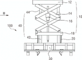
Fig. 1 is a schematic structural view of an exemplary embodiment of a hoisting device.
Fig. 2 is a schematic structural view of the hoisting device in fig. 1 along the direction of an arrow II.
Fig. 3 is a partial structural schematic view of the hoisting device provided with the hoisting device shown in fig. 1.
Fig. 4 is a schematic structural view of the hoisting device of fig. 3 along the direction of an arrow IV.
Description of reference numerals:
10 rigid telescopic mechanism
12 top support
14 telescopic structure
16 elevator
18 bottom bracket
20 flexible connecting mechanism
30 lifting appliance
40 guide mechanism
42 guide post
44 guide sleeve
50 bracket
52 guide rail
54 power device
60 to-be-hoisted object
100 hoisting the device.
Detailed Description
In order to more clearly understand the technical features, objects and effects of the present invention, embodiments of the present invention will be described with reference to the accompanying drawings, wherein the same reference numerals in the drawings refer to the same or similar structural or functional components.
"exemplary" means "serving as an example, instance, or illustration" herein, and any illustration, embodiment, or steps described as "exemplary" herein should not be construed as a preferred or advantageous alternative.
For the sake of simplicity, only the parts relevant to the present invention are schematically shown in the drawings, and they do not represent the actual structure as a product.
Fig. 1 is a schematic structural view of an exemplary embodiment of a lifting device of the present invention. As shown in fig. 1, the hoisting device 100 comprises a rigid telescoping mechanism 10, a flexible connecting mechanism 20, a spreader 30 and a guiding mechanism 40.
In the exemplary embodiment shown in fig. 1, the guiding mechanism 40 includes two pairs of guide posts 42 and guide sleeves 44 (only one pair is labeled for simplicity of drawing), the guide posts 42 are disposed on the spreader 30, and the guide sleeves 44 are disposed on the top bracket 12.
Figure 2 is a schematic view of the hoist 100 as viewed in the direction of arrow II in figure 1. As shown, the guide mechanism 40 includes a guide post 42 and a guide sleeve 44, the guide sleeve 44 having a tapered interface. When the hanger 30 moves up in the direction indicated by the arrow in fig. 2, the guide post 42 moves up, and the hanger 30 is prevented from swinging after the guide post 42 is inserted into the guide sleeve 44.
The hoisting device combines the rigid telescopic mechanism and the flexible connecting mechanism, overcomes the large offset generated in the carrying process of heavy objects such as a battery box and the like, and is beneficial to eliminating potential safety hazards. The flexible connecting mechanism enables the lifting appliance to keep a certain offset, and the lifting appliance is convenient to be butted with an object to be lifted.
In the exemplary embodiment shown in fig. 1, the telescoping structure 14 is a scissor type compressor, which is simple in structure, small in size, and occupies a small area. Without limitation, in other exemplary embodiments, the telescoping structure 14 may take the form of other types of rigid telescoping structures.
In the exemplary embodiment shown in fig. 1, the elevator 16 is a lead screw, which is in threaded connection with the telescopic structure 14 and drives the telescopic structure 14 to extend and retract by rotation. The structure is simple, the control is convenient, and complex control equipment is not needed. But is not limited to such, and other lifting structures may be used for the lift 16 in other exemplary embodiments.
In the illustrated embodiment, the flexible connection mechanism 20 comprises a rope, preferably a steel wire rope, which is simple in structure, versatile, inexpensive, and easy to operate.
Figures 3 and 4 schematically show an exemplary embodiment of the hoisting device according to the utility model. As shown in fig. 3, the lifting device comprises a bracket 50 and a lifting apparatus 100 as shown in fig. 1. As shown in fig. 4, the carriage 50 includes a set of rails 52 and a power unit 54. The jack 12 of the hoist 100 is provided on the guide rail 52, and the hoist 100 is moved on the guide rail 52 in the X direction shown in the figure by the power unit 54. As shown in fig. 3, the hoist 30 of the hoist apparatus 100 lifts the hoisted object 60. The object 60 to be hung may be, for example, a battery box of an electric vehicle.
As shown in fig. 3 and 4, the top holder 12 of the hoist apparatus 100 of the present invention is mounted on the bracket 50, and the hoist apparatus 100 is moved on the guide rail 52 by the power unit 54. The elevator 16 moves the telescopic structure 14 up and down. When in use, the hoisting equipment can be placed on the existing truss track of a carrying site through the bracket 50 for carrying.
The hoisting equipment combines the rigid telescopic mechanism and the flexible connecting mechanism, overcomes the large offset generated in the carrying process of heavy objects such as a battery box and the like, and eliminates potential safety hazards. The flexible connecting mechanism enables the lifting appliance to keep a certain offset, and the lifting appliance is convenient to be butted with a lifted object. The bracket in the hoisting equipment increases the moving dimension, so that the hoisting operation is more convenient.
The above-listed detailed description is only a specific description of a possible embodiment of the present invention, and they are not intended to limit the scope of the present invention, and equivalent embodiments or modifications such as combinations, divisions or repetitions of features, which do not depart from the technical spirit of the present invention, should be included in the scope of the present invention.
Claims (5)
1. Hoist device, its characterized in that includes:
a rigid telescopic mechanism (10) comprising:
a top support (12),
a telescopic structure (14) with one end fixed on the top support (12),
a lift (16) connected to said telescopic structure (14) and capable of bringing said telescopic structure (14) to telescope, an
A shoe (18) connected to the other end of said telescopic structure (14);
a flexible connection mechanism (20) connected to said shoe (18);
a hanger (30) with one end connected with the flexible connecting mechanism (20) and the other end selectively connected with an object to be hung; and
and the guide mechanism (40) comprises a plurality of pairs of guide columns (42) and guide sleeves (44), the guide columns (42) are arranged on the lifting appliance (30), and the guide sleeves (44) are arranged on the jacking plate (12).
2. The hoisting device according to claim 1, wherein the telescopic structure (14) is a scissor-type compressor.
3. Hoist device according to claim 1, wherein the elevator (16) is a lead screw.
4. A lifting device according to claim 1, wherein the flexible attachment means (20) comprises a rope.
5. Lifting device, its characterized in that includes:
a lifting device as claimed in any one of claims 1 to 4; and
a cradle (50), said cradle (50) comprising:
a set of guide rails (52), on which the hoisting device is arranged on, and
a power device (54), wherein the power device (54) can drive the hoisting device to move.
Priority Applications (2)
| Application Number | Priority Date | Filing Date | Title |
|---|---|---|---|
| CN202122509497.8U CN216807858U (en) | 2021-10-19 | 2021-10-19 | Hoisting device and hoisting equipment |
| PCT/CN2022/074696 WO2023065569A1 (en) | 2021-10-19 | 2022-01-28 | Hoisting apparatus and hoisting equipment |
Applications Claiming Priority (1)
| Application Number | Priority Date | Filing Date | Title |
|---|---|---|---|
| CN202122509497.8U CN216807858U (en) | 2021-10-19 | 2021-10-19 | Hoisting device and hoisting equipment |
Publications (1)
| Publication Number | Publication Date |
|---|---|
| CN216807858U true CN216807858U (en) | 2022-06-24 |
Family
ID=82048435
Family Applications (1)
| Application Number | Title | Priority Date | Filing Date |
|---|---|---|---|
| CN202122509497.8U Active CN216807858U (en) | 2021-10-19 | 2021-10-19 | Hoisting device and hoisting equipment |
Country Status (2)
| Country | Link |
|---|---|
| CN (1) | CN216807858U (en) |
| WO (1) | WO2023065569A1 (en) |
Family Cites Families (6)
| Publication number | Priority date | Publication date | Assignee | Title |
|---|---|---|---|---|
| US5252024A (en) * | 1991-11-04 | 1993-10-12 | General Motors Corporation | Transfer method for various sizes of assemblies |
| CN1544307A (en) * | 2003-11-26 | 2004-11-10 | 中国建筑第八工程局工业设备安装公司 | Multifunctional engineering installation vehicle |
| CN205257752U (en) * | 2015-12-23 | 2016-05-25 | 郑州日产汽车有限公司 | Automatic mechanism that reaches standard grade of vapour car roof |
| CN111204239A (en) * | 2018-11-22 | 2020-05-29 | 青岛海汇德电气有限公司 | Charging equipment and use method thereof |
| CN209583420U (en) * | 2018-12-11 | 2019-11-05 | 湖北鸿锦机电设备有限公司 | A kind of crossing type lifting apparatus |
| CN212654233U (en) * | 2020-09-25 | 2021-03-05 | 深圳精智机器有限公司 | Electricity replacing system of pure electric heavy truck |
-
2021
- 2021-10-19 CN CN202122509497.8U patent/CN216807858U/en active Active
-
2022
- 2022-01-28 WO PCT/CN2022/074696 patent/WO2023065569A1/en unknown
Also Published As
| Publication number | Publication date |
|---|---|
| WO2023065569A1 (en) | 2023-04-27 |
Similar Documents
| Publication | Publication Date | Title |
|---|---|---|
| CN105449562A (en) | Central-positioned type switch chassis overhaul device | |
| CN201622860U (en) | Fuel operating device | |
| CN208054811U (en) | A kind of portable hinge connecting rod lifting device | |
| CN207792583U (en) | Busbar handling device | |
| CN201087076Y (en) | Gantry crane | |
| CN207108405U (en) | Portable light-duty jacking apparatus | |
| CN216807858U (en) | Hoisting device and hoisting equipment | |
| CN203269454U (en) | Crane coiling block maintenance lifting device | |
| CN204167749U (en) | A kind of middle switch chassis apparatus for examination and repair | |
| CN205027879U (en) | Installation device of test motor | |
| CN205312922U (en) | 1000kV cluster benefit equipment is repaiied examination special use and is lifted by crane instrument | |
| CN210341634U (en) | Viaduct outer wall painting crane | |
| CN214495431U (en) | Prefabricated component installation auxiliary device | |
| CN113666274A (en) | Intelligent lifting device for building | |
| CN211169604U (en) | Porcelain insulator lifting device used in transformer substation | |
| CN209974209U (en) | BOP shifting and transporting device | |
| CN107618999B (en) | Hoisting tool and hoisting method for narrow space of bridge beam bottom and pier stud | |
| CN218893407U (en) | Material lifting device for building construction | |
| CN220555624U (en) | Traffic engineering maintenance elevating gear | |
| CN218950932U (en) | Diamond line busbar mounting device | |
| CN220412709U (en) | Pipeline hoisting accessory | |
| CN202924676U (en) | Rapid lifting device | |
| CN214459254U (en) | Rail translation device | |
| CN220618184U (en) | Clamping conveying crane | |
| CN215890006U (en) | Oil field logging instrument carrier |
Legal Events
| Date | Code | Title | Description |
|---|---|---|---|
| GR01 | Patent grant | ||
| GR01 | Patent grant |