CN216781237U - Rim processing preprocessing device - Google Patents
Rim processing preprocessing device Download PDFInfo
- Publication number
- CN216781237U CN216781237U CN202220020970.8U CN202220020970U CN216781237U CN 216781237 U CN216781237 U CN 216781237U CN 202220020970 U CN202220020970 U CN 202220020970U CN 216781237 U CN216781237 U CN 216781237U
- Authority
- CN
- China
- Prior art keywords
- rim
- support
- top end
- driving gear
- clamping
- Prior art date
- Legal status (The legal status is an assumption and is not a legal conclusion. Google has not performed a legal analysis and makes no representation as to the accuracy of the status listed.)
- Active
Links
Images


Abstract
The utility model discloses a rim processing pretreatment device, which comprises a collecting box, wherein the top end of the collecting box is provided with a support, the top of the support is provided with a chute, the edge of the support is positioned in the chute and clamped with a clamping column, the outer surface of the clamping column is in threaded connection with a fastening bolt, the top end of the clamping column is fixedly connected with a support rod, the top end of the support rod is provided with a limit plate, one end of the limit plate is provided with a fixture block, the clamping column is clamped in the chute arranged at the top end of the support, a rim to be processed is placed between four fixture blocks positioned on four sides, the position of the clamping column on the top of the support is moved according to the size of the rim, after the rim is clamped, the clamping bolt is rotated to fix the clamping column and the support, the fixture blocks are in an X-shaped structure, so that a plurality of surfaces of the fixture blocks can clamp the rim, and the rim is fixed between the four fixture blocks in an extruding or clamping way, the flexibility of rim processing location has been improved.
Description
Technical Field
The utility model relates to the technical field of rim processing, in particular to a rim processing pretreatment device.
Background
Rim and spoke can be integral, permanent connection formula or detachable, need polish the preliminary treatment operation in the rim production course of working, get rid of the dust impurity on rim surface, when traditional rim polished, often need artifical manual fixed rim of pressing down, need a large amount of manpowers, improved rim processing cost to there is certain potential safety hazard in the rim process of polishing, the manual work is polished and is operated and not only wastes time and energy, has the risk of accidental injury moreover. Therefore, the improvement is made, and a wheel rim processing pretreatment device is provided.
SUMMERY OF THE UTILITY MODEL
In order to solve the technical problems, the utility model provides the following technical scheme:
the utility model discloses a rim processing pretreatment device, which comprises a collecting box, wherein a support is arranged at the top end of the collecting box, a sliding groove is formed in the top of the support, a clamping column is clamped at the edge of the support in the sliding groove, a fastening bolt is connected to the outer surface of the clamping column in a threaded manner, a supporting rod is fixedly connected to the top end of the clamping column, a limiting plate is arranged at the top end of the supporting rod, a clamping block is arranged at one end of the limiting plate, a clamping sleeve is arranged at the other end of the limiting plate, a driving gear is rotatably connected to the inner bottom end of the collecting box through a rotating shaft, four driven gears are meshed with the outside of the driving gear, a shaft lever is arranged at the central position of the driving gear, and an iron brush is arranged at one end of the shaft lever.
As a preferable technical scheme of the utility model, the number of the clamping columns is four, and the height of each clamping column is higher than that of the top end of the support.
As a preferable technical scheme of the utility model, the clamping column, the supporting rod and the limiting plate are all rectangular structures.
As a preferred technical scheme of the utility model, the top end of the supporting rod is fixedly provided with a circular disc, and the cutting sleeve is sleeved on the outer surface of the supporting rod and is positioned below the cutting sleeve.
As a preferable technical scheme, the clamping block is of an X-shaped structure, and the limiting plate is vertically connected with the supporting rod.
As a preferable technical scheme of the utility model, the central positions of the outer surfaces of the four driven gears are respectively provided with a shaft rod and an iron brush, and the diameters of the driven gears are smaller than those of the driving gears.
As a preferred technical scheme of the utility model, the collection box is internally provided with a collection cavity, and the driving gear and the driven gear are positioned in the collection cavity.
The utility model has the beneficial effects that:
1. this rim processing preprocessing device, inside the spout that the card post joint was seted up on the support top, will treat to process the rim and place and go on between four fixture blocks that are located four side positions, move the position of card post at the support top according to the size of rim, after the rim presss from both sides tightly, fix through rotatory fastening bolt so that will block between post and the support, wherein the fixture block is "X" type structure, thereby a plurality of surfaces of fixture block all can carry out the centre gripping to the rim, make the rim fix between four fixture blocks through the mode of extrusion or block, the flexibility of rim processing location has been improved.
2. This rim processing preprocessing device, it is rotatory to drive the driving gear through the motor, the driving gear drives and rotates rather than four driven gear of meshing, because driven gear's diameter is less than the diameter of driving gear, consequently driven gear's rotational speed is greater than the rotational speed of driving gear, driving gear and driven gear's surface all is provided with axostylus axostyle and iron brush, make the iron brush contact polish the efficiency of polishing that the high-speed pivoted driven gear of rim helps improving the iron brush at the surface of rim, get rid of the dust dirt of rim surface, the follow-up processing of the rim of being convenient for, the inside of collecting the chamber is stored to the dirt bits whereabouts of polishing the removal on the rim, convenient unified processing.
Drawings
The accompanying drawings, which are included to provide a further understanding of the utility model and are incorporated in and constitute a part of this specification, illustrate embodiments of the utility model and together with the description serve to explain the principles of the utility model and not to limit the utility model. In the drawings:
FIG. 1 is a schematic structural diagram of the outline of a rim processing pretreatment device according to the utility model;
FIG. 2 is a schematic view of a collection chamber of a rim processing pretreatment apparatus according to the present invention;
FIG. 3 is a schematic structural diagram of a top view of a brush installation position of the rim machining pretreatment device according to the present invention;
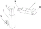
fig. 4 is a schematic diagram of a fixture block connection structure of the rim machining preprocessing device.
In the figure: 1. a collection box; 2. a support; 3. a chute; 4. clamping the column; 5. fastening a bolt; 6. a support bar; 7. a limiting plate; 8. a clamping block; 9. a card sleeve; 10. a driving gear; 11. a driven gear; 12. a shaft lever; 13. an iron brush; 14. a collection chamber.
Detailed Description
The preferred embodiments of the present invention will be described in conjunction with the accompanying drawings, and it will be understood that they are described herein for the purpose of illustration and explanation and not limitation.
Example (b): as shown in fig. 1-4, the rim processing pretreatment device comprises a collection box 1, a support 2 is arranged at the top end of the collection box 1, a sliding groove 3 is formed in the top of the support 2, a clamping column 4 is clamped in the sliding groove 3 at the edge of the support 2, a fastening bolt 5 is connected to the outer surface of the clamping column 4 in a threaded manner, a support rod 6 is fixedly connected to the top end of the clamping column 4, a limiting plate 7 is arranged at the top end of the support rod 6, a clamping block 8 is arranged at one end of the limiting plate 7, a clamping sleeve 9 is arranged at the other end of the limiting plate 7, a driving gear 10 is rotatably connected to the bottom end of the interior of the collection box 1 through a rotating shaft, four driven gears 11 are meshed with the exterior of the driving gear 10, a shaft lever 12 is arranged at the central position of the driving gear 10, and an iron brush 13 is arranged at one end of the shaft lever 12.
Wherein, the number of the clamping columns 4 is four, the height of the clamping column 4 is higher than the top end of the bracket 2, the clamping column 4, the supporting rod 6 and the limiting plate 7 are all rectangular structures, the top end of the supporting rod 6 is fixedly provided with a disc, the sleeve 9 is sleeved on the outer surface of the supporting rod 6 and is positioned below the sleeve 9, the clamping block 8 is in an X-shaped structure, the limiting plate 7 is vertically connected with the supporting rod 6, the clamping column 4 is clamped in the sliding chute 3 arranged at the top end of the bracket 2, a rim to be processed is placed between the four clamping blocks 8 positioned at the four sides, the position of the clamping column 4 at the top of the bracket 2 is moved according to the size of the rim, after the rim is clamped, the clamping column 4 and the bracket 2 are fixed by rotating the fastening bolt 5, wherein the clamping block 8 is in the X-shaped structure, so that the plurality of surfaces of the clamping block 8 can clamp the rim, and the rim is fixed between the four clamping blocks 8 in an extruding or clamping way, the flexibility of rim processing location has been improved.
Wherein, the central position of the outer surface of four driven gears 11 is provided with a shaft lever 12 and an iron brush 13, the diameter of the driven gear 11 is smaller than that of the driving gear 10, the inside of the collecting box 1 is provided with a collecting cavity 14, the driving gear 10 and the driven gear 11 are positioned inside the collecting cavity 14, the driving gear 10 is driven by a motor to rotate, the driving gear 10 drives the four driven gears 11 engaged with the driving gear to rotate, because the diameter of the driven gear 11 is smaller than that of the driving gear 10, the rotating speed of the driven gear 11 is greater than that of the driving gear 10, the outer surfaces of the driving gear 10 and the driven gear 11 are provided with the shaft lever 12 and the iron brush 13, the driven gear 11 which is in contact with the outer surface of the rim to polish the rim and rotates at high speed is beneficial to improving the polishing efficiency of the iron brush 13, the dust on the outer surface of the rim is removed, and the subsequent processing of the rim is convenient, the dust and scraps polished and removed on the rim fall into the collecting cavity 14 for storage, so that uniform treatment is facilitated.
The working principle is as follows: clamping a clamping column 4 in a sliding groove 3 arranged at the top end of a support 2, placing a rim to be processed between four clamping blocks 8 positioned at four sides, moving the position of the clamping column 4 at the top of the support 2 according to the size of the rim, fixing the clamping column 4 and the support 2 by rotating a fastening bolt 5 after the rim is clamped, wherein the clamping blocks 8 are in an X-shaped structure, so that a plurality of surfaces of the clamping blocks 8 can clamp the rim, the rim is fixed between the four clamping blocks 8 in an extruding or clamping way, the flexibility of rim processing and positioning is improved, a driving gear 10 is driven by a motor to rotate, the driving gear 10 drives four driven gears 11 meshed with the driving gear 10 to rotate, and the rotating speed of the driven gears 11 is greater than that of the driving gear 10 because the diameter of the driven gears 11 is smaller than that of the driving gear 10, the outer surfaces of the driving gear 10 and the driven gear 11 are provided with the shaft rod 12 and the iron brushes 13, so that the iron brushes 13 are in contact with the driven gear 11 which is arranged on the outer surface of the rim and used for polishing the rim at a high speed, the polishing efficiency of the iron brushes 13 is improved, dust and dirt on the outer surface of the rim are removed, the subsequent processing treatment of the rim is facilitated, dust and dirt removed by polishing on the rim fall to the inside of the collection cavity 14 to be stored, and the uniform treatment is facilitated.
Finally, it should be noted that: in the description of the present invention, it should be noted that the terms "vertical", "upper", "lower", "horizontal", and the like indicate orientations or positional relationships based on those shown in the drawings, and are only for convenience of describing the present invention and simplifying the description, but do not indicate or imply that the referred device or element must have a specific orientation, be constructed in a specific orientation, and be operated, and thus, should not be construed as limiting the present invention.
In the description of the present invention, it should also be noted that, unless otherwise explicitly specified or limited, the terms "disposed," "mounted," "connected," and "connected" are to be construed broadly and may, for example, be fixedly connected, detachably connected, or integrally connected; can be mechanically or electrically connected; they may be connected directly or indirectly through intervening media, or they may be interconnected between two elements. The specific meanings of the above terms in the present invention can be understood by those skilled in the art according to specific situations.
Although the present invention has been described in detail with reference to the foregoing embodiments, it will be apparent to those skilled in the art that changes may be made in the embodiments and/or equivalents thereof without departing from the spirit and scope of the utility model. Any modification, equivalent replacement, or improvement made within the spirit and principle of the present invention should be included in the protection scope of the present invention.
Claims (7)
1. A rim processing pretreatment device comprises a collection box (1) and is characterized in that a support (2) is arranged at the top end of the collection box (1), a sliding groove (3) is formed in the top of the support (2), a clamping column (4) is clamped in the sliding groove (3) at the edge of the support (2), a fastening bolt (5) is connected to the outer surface of the clamping column (4) in a threaded manner, a support rod (6) is fixedly connected to the top end of the clamping column (4), a limiting plate (7) is arranged at the top end of the support rod (6), a clamping block (8) is arranged at one end of the limiting plate (7), a clamping sleeve (9) is arranged at the other end of the limiting plate (7), a driving gear (10) is rotatably connected to the inner bottom end of the collection box (1) through a rotating shaft, four driven gears (11) are meshed outside the driving gear (10), a shaft rod (12) is arranged at the central position of the driving gear (10), and an iron brush (13) is arranged at one end of the shaft rod (12).
2. A rim machining preprocessing device according to claim 1 characterized in that the number of the clamp columns (4) is four, and the height of the clamp columns (4) is higher than the top end of the bracket (2).
3. A rim machining preprocessing device according to claim 1 wherein, the jamming column (4), the support rod (6) and the limit plate (7) are all rectangular structures.
4. A rim processing pretreatment device according to claim 1, characterized in that a disc is fixedly disposed on the top end of the support rod (6), and the cutting sleeve (9) is sleeved on the outer surface of the support rod (6) and is located below the cutting sleeve (9).
5. A rim machining preprocessing device according to claim 1 wherein the fixture block (8) is "X" type structure, the limiting plate (7) is vertically connected with the support rod (6).
6. A rim machining preprocessing device according to claim 1 characterized in that the center of the outer surface of each of the four driven gears (11) is provided with a shaft (12) and an iron brush (13), and the diameter of the driven gear (11) is smaller than that of the driving gear (10).
7. A rim processing preprocessing device according to claim 1 wherein, the collecting box (1) is opened with a collecting chamber (14), the driving gear (10) and the driven gear (11) are located inside the collecting chamber (14).
Priority Applications (1)
| Application Number | Priority Date | Filing Date | Title |
|---|---|---|---|
| CN202220020970.8U CN216781237U (en) | 2022-01-06 | 2022-01-06 | Rim processing preprocessing device |
Applications Claiming Priority (1)
| Application Number | Priority Date | Filing Date | Title |
|---|---|---|---|
| CN202220020970.8U CN216781237U (en) | 2022-01-06 | 2022-01-06 | Rim processing preprocessing device |
Publications (1)
| Publication Number | Publication Date |
|---|---|
| CN216781237U true CN216781237U (en) | 2022-06-21 |
Family
ID=82013306
Family Applications (1)
| Application Number | Title | Priority Date | Filing Date |
|---|---|---|---|
| CN202220020970.8U Active CN216781237U (en) | 2022-01-06 | 2022-01-06 | Rim processing preprocessing device |
Country Status (1)
| Country | Link |
|---|---|
| CN (1) | CN216781237U (en) |
-
2022
- 2022-01-06 CN CN202220020970.8U patent/CN216781237U/en active Active
Similar Documents
| Publication | Publication Date | Title |
|---|---|---|
| CN114378584B (en) | Cutting device is used in metal pipeline production | |
| CN209754883U (en) | Driving device for hub grinding equipment | |
| CN213770441U (en) | Feeding device for mechanical automation production | |
| CN216781237U (en) | Rim processing preprocessing device | |
| CN211361738U (en) | Workpiece surface polishing treatment equipment | |
| CN113146374A (en) | Surface finish machining device and method for input belt wheel shaft | |
| CN216265076U (en) | Steel pipe burr remove device for machine-building | |
| CN115502808A (en) | Deburring device for automobile hub production | |
| CN211966906U (en) | Recyclable polishing device for machining of sweeps | |
| CN213795759U (en) | A grinding device for production of precision machine part | |
| CN210189116U (en) | Gear sleeve machining device | |
| CN213258597U (en) | Dustless formula metal parts machining grinding device | |
| CN210452120U (en) | Bearing chamfering processing equipment capable of removing burrs | |
| CN210756799U (en) | Steel pipe grinding device convenient to it is fixed | |
| CN210616092U (en) | Polishing device for production of drainage floor drain | |
| CN112497041A (en) | Novel suspension polishing equipment | |
| CN112404104A (en) | Waste welding electrode coating removing and separating device and method | |
| CN216138668U (en) | Bottom grinding equipment for processing artware | |
| CN215847227U (en) | Horizontal milling machine is used in processing of pipe class spare | |
| CN220533765U (en) | Surface pretreatment device for forge welding | |
| CN218904806U (en) | Polishing equipment easy to maintain | |
| CN220637318U (en) | Part surface grinding device | |
| CN216882915U (en) | Piece collection device of digit control machine tool | |
| CN113770910B (en) | Graded grinding device for processing automobile brake pads | |
| CN220660404U (en) | Mould burnishing device |
Legal Events
| Date | Code | Title | Description |
|---|---|---|---|
| GR01 | Patent grant | ||
| GR01 | Patent grant |