CN216686558U - Automatic stacking equipment of punching machine - Google Patents
Automatic stacking equipment of punching machine Download PDFInfo
- Publication number
- CN216686558U CN216686558U CN202122997106.1U CN202122997106U CN216686558U CN 216686558 U CN216686558 U CN 216686558U CN 202122997106 U CN202122997106 U CN 202122997106U CN 216686558 U CN216686558 U CN 216686558U
- Authority
- CN
- China
- Prior art keywords
- stacking
- pile
- neatly
- punching machine
- translation mechanism
- Prior art date
- Legal status (The legal status is an assumption and is not a legal conclusion. Google has not performed a legal analysis and makes no representation as to the accuracy of the status listed.)
- Active
Links
Images


Classifications
-
- Y—GENERAL TAGGING OF NEW TECHNOLOGICAL DEVELOPMENTS; GENERAL TAGGING OF CROSS-SECTIONAL TECHNOLOGIES SPANNING OVER SEVERAL SECTIONS OF THE IPC; TECHNICAL SUBJECTS COVERED BY FORMER USPC CROSS-REFERENCE ART COLLECTIONS [XRACs] AND DIGESTS
- Y02—TECHNOLOGIES OR APPLICATIONS FOR MITIGATION OR ADAPTATION AGAINST CLIMATE CHANGE
- Y02E—REDUCTION OF GREENHOUSE GAS [GHG] EMISSIONS, RELATED TO ENERGY GENERATION, TRANSMISSION OR DISTRIBUTION
- Y02E60/00—Enabling technologies; Technologies with a potential or indirect contribution to GHG emissions mitigation
- Y02E60/10—Energy storage using batteries
Abstract
The utility model discloses automatic stacking equipment of a punching machine, belongs to the technical field of stacking equipment, solves the technical problem of high labor intensity of manual carrying after stacking of stamping parts, this equipment includes pile up neatly device and sets up the conveyor in pile up neatly device one side, the pile up neatly device includes the pile up neatly platform, the pile up neatly tool, be provided with the graduated disk on the pile up neatly platform, be provided with several U type mounting panel on the graduated disk, U type mounting panel both sides all are equipped with the spout, the activity of pile up neatly tool sets up in the spout, U type mounting panel bottom both sides are provided with the installation piece respectively, all be connected with the dog through the bolt rotation on every installation piece, the one corner that is close to punching machine and conveyor on the pile up neatly platform is provided with locating component through the support, conveyor is used for transporting the stamping workpiece from the punching machine on the pile up neatly platform, this equipment can reduce operation personnel's working strength, and the production efficiency is improved.
Description
Technical Field
The utility model belongs to the technical field of stacking equipment, and particularly relates to automatic stacking equipment of a punching machine.
Background
The metalwork is after stamping process, need carry fashioned metalwork and pile up neatly, but adopt artifical transport and pile up neatly among the prior art on the one hand, these operations need a plurality of operating personnel to participate in, not only operating personnel working strength is big, low in production efficiency, and there is certain potential safety hazard, also adopt the machine to carry and pile up neatly, nevertheless accomplish the back at the pile up neatly, because through screw locking connection between pile up neatly tool and the pile up neatly platform, can't carry with the machine, just need the manual work to dismantle the pile up neatly tool earlier and carry the good stamping workpiece of pile up neatly from the pile up neatly platform again, staff's working strength has been increased like this, and is inefficient, for solving this with technical problem, an automatic pile up neatly equipment of punching machine is provided.
SUMMERY OF THE UTILITY MODEL
The utility model aims to overcome the technical problem of the prior art, and provides automatic stacking equipment of a punching machine, which can replace manual carrying and stacking, improve the production efficiency, and can carry the stacked jig from a stacking table through a machine, thereby reducing the working strength of operators.
In order to achieve the purpose, the following technical scheme is provided: the automatic stacking equipment of the punching machine comprises a stacking device and a conveying device, wherein the conveying device is arranged on one side of the stacking device, the stacking device comprises a stacking table and a stacking jig, an index plate is arranged on the stacking table, a U-shaped mounting plate is arranged on the index plate corresponding to each station, sliding chutes are arranged on two sides of the U-shaped mounting plate, the stacking jig is movably arranged in the sliding chutes, mounting blocks are respectively arranged on two sides of the bottom end of the U-shaped mounting plate, a stop block is rotatably connected on each mounting block through a bolt, a positioning assembly is arranged on one corner of the stacking table close to the punching machine and the conveying device through a support, the conveying device comprises a lifting translation mechanism, a first grabbing piece and a second grabbing piece, the lifting translation mechanism is used for driving the first grabbing piece to convey a stamping piece on the punching machine to the positioning assembly, and driving the second grabbing piece to convey the stamping piece on the positioning assembly to the stacking jig, and a photoelectric sensor used for detecting the stacking height of the stamping parts is arranged on one side of the stacking platform corresponding to the first grabbing part.
Compared with the prior art, the utility model has the following beneficial effects:
1. according to the automatic stacking device, automatic stacking is realized through the matching of the stacking device and the conveying device, manual carrying is replaced, the working intensity of operating personnel is reduced, and the production efficiency is improved;
2. the indexing disc is arranged on the stacking platform, so that stacking of a plurality of stations can be realized, the size is small, the structure is compact, and the production space is saved;
3. can realize that pile up neatly tool and graduated disk can dismantle to be connected through setting up U type mounting panel on the graduated disk, the transport in the later stage of being convenient for sets up the installation piece respectively in U type mounting panel both sides, all is connected with the dog through the bolt rotation on every installation piece, when the bolt is screwed up, the dog is parallel with U type mounting panel this moment, avoids the pile up neatly tool at pile up neatly in-process landing, when taking out the pile up neatly tool, only need unscrew the bolt, rotate the dog with U type mounting panel perpendicularly can.
Drawings
The accompanying drawings, which are incorporated in and constitute a part of this specification, illustrate embodiments consistent with the disclosure and together with the description, serve to explain the principles of the disclosure.
FIG. 1 is a side view of an automatic palletizing apparatus of a punch press;
FIG. 2 is a schematic structural view of an automatic stacking device of a punching machine;
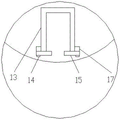
FIG. 3 is a top view of the U-shaped mounting plate;
fig. 4 is a plan view of the U-shaped mounting plate.
Reference numerals:
the stacking device 10, the X-axis translation mechanism 20, the Z-axis translation mechanism 30, the first grabbing member 40, the second grabbing member 50, the positioning assembly 60, the photoelectric sensor 70, the stamping part 80, the stacking platform 11, the dividing disc 12, the U-shaped mounting plate 13, the sliding chute 131, the bolt 14, the stop dog 15, the stacking jig 16, the mounting block 17, the rack 21, the first motor 22, the X-axis bracket 23, the gear 24, the rack 25, the second motor 31, the screw rod 32, the mounting plate 33, the bracket 61, the bearing plate 62 and the adjusting and positioning block group 63.
Detailed Description
The technical solutions in the embodiments of the present invention will be clearly and completely described below with reference to the drawings in the embodiments of the present invention, and it is obvious that the described embodiments are only a part of the embodiments of the present invention, and not all of the embodiments.
Examples
Referring to fig. 1-2, automatic stacking equipment of punching machine, including pile up neatly device 10, conveyor sets up in pile up neatly device 10 one side, pile up neatly device 10 includes pile up neatly platform 11, pile up neatly tool 16, be provided with graduated disk 12 on the pile up neatly platform 11, graduated disk 12 corresponds every station department and all is provided with U type mounting panel 13, U type mounting panel 13 both sides all are equipped with spout 131, pile up neatly tool 16 activity sets up in the spout, U type mounting panel 13 bottom both sides are provided with installation piece 17 respectively, every all be connected with dog 15 through bolt 14 rotation on the installation piece 17, the one corner that is close to punching machine and conveyor on the pile up neatly platform 11 is provided with locating component 60 through support 61, conveyor includes lifting and translation mechanism, first grabbing piece 40, second grabbing piece 50, lifting and translation mechanism is used for driving first grabbing piece 40 and carries the 80 on the punching machine to the locating component 60, and fixes a position The second grabbing part 50 is driven by the second grabbing part 60 to convey the stamped parts 80 on the positioning assembly 60 to the stacking jig 16, and a photoelectric sensor 70 used for detecting the stacking height of the stamped parts 80 is arranged on one side, corresponding to the first grabbing part 40, of the stacking table 11.
According to the automatic stacking device, automatic stacking is realized through the matching of the stacking device 10 and the conveying device, manual carrying is replaced, the working strength of operators is reduced, and the production efficiency is improved; through set up the gyration sabot on pile up neatly platform 11, not only can realize a plurality of station pile up neatly, and small in addition, compact structure, practice thrift the production space, can realize pile up neatly tool 16 and graduated disk 12 can dismantle through setting up U type mounting panel 13 on graduated disk 12 and be connected, the transport in the later stage of being convenient for, set up installation piece 17 respectively in U type mounting panel 13 both sides, all rotate through bolt 14 on every installation piece 17 and be connected with dog 15, when bolt 14 is screwed up, dog 15 is parallel with U type mounting panel 13 this moment, avoid pile up neatly tool 16 at pile up neatly in-process landing, when taking out pile up neatly tool 16, only need unscrew bolt 14, rotate dog 15 perpendicular with U type mounting panel 13 can.
In this embodiment, the lifting translation mechanism includes a frame 21, an X-axis translation mechanism 20, and a Z-axis translation mechanism 30, where the Z-axis translation mechanism 30 includes a second motor 31 fixedly disposed on the frame 21, and a lead screw 32 provided with an output end of the second motor 31, the X-axis translation mechanism 20 includes a first motor 22 fixedly disposed on the frame 21, and an X-axis bracket 23 slidably disposed on the lead screw through a mounting plate 33, an output end of the first motor 22 is provided with a gear 24, the X-axis bracket 23 is slidably provided with a rack 25, and the gear 24 is engaged with the rack 25.
In this embodiment, the first grabbing member 40 is arranged at one end of the rack 25 corresponding to the punching machine, the second grabbing member 50 is arranged in the middle of the rack 25, the stacking jig 16 which is close to the X-axis support 23 and is right opposite to the X-axis support 23 on the dividing disc 12 is used as a stamping part 80 material placing position, the distance between the first grabbing member 40 and the second grabbing member 50 is equal to the distance between the positioning assembly 60 and the stacking jig 16 when the stacking jig 16 is transferred to the material placing position, and therefore the design can avoid the use of the overlong rack 25, save the production space and improve the working efficiency.
In this embodiment, the positioning assembly 60 includes a carrier plate 62 disposed on the bracket 61, and a positioning cylinder and a plurality of adjusting and positioning block sets 63 disposed on the carrier plate 62, and the angle of the product can be adjusted by disposing the positioning assembly 60.
According to the working principle of the automatic stacking device of the punching machine, the automatic stacking device of the punching machine is arranged beside the punching machine, after punching of the punching machine is completed, the lifting translation mechanism drives the first grabbing part 40 to move the stamping part 80 from the punching machine to the positioning assembly 60, the lifting translation mechanism drives the first grabbing part 40 to grab the stamping part 80 from the punching machine again, meanwhile, the second grabbing part 50 moves the stamping part 80 on the positioning assembly 60 to the stacking jig 16, the operation is repeated, the carrying and stacking of the stamping part 80 are completed, after the stacking is completed, the bolt 14 needs to be unscrewed, the stopper 15 needs to be rotated to be perpendicular to the U-shaped mounting plate 13, and then the stacking jig 16 is pulled out of the U-shaped mounting plate 13 along the sliding groove 131 by the machine.
In conclusion, through using automatic pile up neatly equipment of punching machine not only can replace artifical transport and pile up neatly, improve production efficiency, but also can carry the tool that the pile up neatly was accomplished from pile up neatly platform 11 through the machine, reduce operation personnel's working strength.
The above embodiments are merely illustrative of the technical ideas and features of the present invention, and are intended to enable those skilled in the art to understand the contents of the present invention and implement the present invention, and not to limit the scope of the present invention. All equivalent changes or modifications made according to the spirit of the present invention should be covered within the protection scope of the present invention.
Claims (4)
1. The automatic stacking equipment of the punching machine is characterized by comprising a stacking device and a conveying device, wherein the conveying device is arranged on one side of the stacking device, the stacking device comprises a stacking table and a stacking jig, an index plate is arranged on the stacking table, a U-shaped mounting plate is arranged on the index plate corresponding to each station, sliding chutes are formed in two sides of the U-shaped mounting plate, the stacking jig is movably arranged in the sliding chutes, mounting blocks are respectively arranged on two sides of the bottom end of the U-shaped mounting plate, a stop block is rotatably connected onto each mounting block through a bolt, a positioning assembly is arranged on one corner, close to the punching machine and the conveying device, of the stacking table through a support, the conveying device comprises a lifting translation mechanism, a first grabbing piece and a second grabbing piece, and the lifting translation mechanism is used for driving the first grabbing piece to convey a stamping piece on the punching machine to the positioning assembly, the second grabbing piece is driven to convey the stamping parts on the positioning assembly to the stacking jig, and a photoelectric sensor used for detecting the stacking height of the stamping parts is arranged on one side, corresponding to the first grabbing piece, of the stacking table.
2. The automatic stacking device of punching machines according to claim 1, wherein the lifting translation mechanism comprises a frame, an X-axis translation mechanism and a Z-axis translation mechanism, the Z-axis translation mechanism comprises a second motor fixedly arranged on the frame, a screw rod arranged at the output end of the second motor, the X-axis translation mechanism comprises a first motor fixedly arranged on the frame, and an X-axis support slidably arranged on the screw rod through a mounting plate, the output end of the first motor is provided with a gear, the X-axis support is slidably provided with a rack, and the gear is meshed with the rack.
3. The automatic stacking machine of punching machines according to claim 1, wherein the first gripping member is arranged at one end of the rack corresponding to the punching machine, the second gripping member is arranged in the middle of the rack, the stacking jig on the dividing plate, which is close to the X-axis support and opposite to the X-axis support, is a stamping part placing position, and the distance between the first gripping member and the second gripping member is equal to the distance between the positioning assembly and the stacking jig when the stacking jig is transferred to the placing position.
4. The automatic palletizing machine according to claim 1, wherein the positioning assembly comprises a bearing plate arranged on the support, and a positioning cylinder and a plurality of adjusting and positioning block sets arranged on the bearing plate.
Priority Applications (1)
| Application Number | Priority Date | Filing Date | Title |
|---|---|---|---|
| CN202122997106.1U CN216686558U (en) | 2021-12-01 | 2021-12-01 | Automatic stacking equipment of punching machine |
Applications Claiming Priority (1)
| Application Number | Priority Date | Filing Date | Title |
|---|---|---|---|
| CN202122997106.1U CN216686558U (en) | 2021-12-01 | 2021-12-01 | Automatic stacking equipment of punching machine |
Publications (1)
| Publication Number | Publication Date |
|---|---|
| CN216686558U true CN216686558U (en) | 2022-06-07 |
Family
ID=81836311
Family Applications (1)
| Application Number | Title | Priority Date | Filing Date |
|---|---|---|---|
| CN202122997106.1U Active CN216686558U (en) | 2021-12-01 | 2021-12-01 | Automatic stacking equipment of punching machine |
Country Status (1)
| Country | Link |
|---|---|
| CN (1) | CN216686558U (en) |
Cited By (1)
| Publication number | Priority date | Publication date | Assignee | Title |
|---|---|---|---|---|
| CN115973782A (en) * | 2023-02-16 | 2023-04-18 | 重庆协兴同创环保科技有限公司 | Finished product carton stacking equipment with automatic positioning mechanism |
-
2021
- 2021-12-01 CN CN202122997106.1U patent/CN216686558U/en active Active
Cited By (2)
| Publication number | Priority date | Publication date | Assignee | Title |
|---|---|---|---|---|
| CN115973782A (en) * | 2023-02-16 | 2023-04-18 | 重庆协兴同创环保科技有限公司 | Finished product carton stacking equipment with automatic positioning mechanism |
| CN115973782B (en) * | 2023-02-16 | 2023-06-20 | 重庆协兴同创环保科技有限公司 | Finished product carton pile up neatly equipment with automatic positioning mechanism |
Similar Documents
| Publication | Publication Date | Title |
|---|---|---|
| US11571774B2 (en) | Intelligent plate parts machining production line combining universal and special equipment | |
| CN112059035B (en) | Multi-station fixed clamping automatic stamping equipment based on multi-axis industrial robot | |
| CN206065429U (en) | A kind of motor shaft automatic chamfering device | |
| CN216686558U (en) | Automatic stacking equipment of punching machine | |
| CN106825135A (en) | A kind of machine for press-bending metal sheet | |
| CN201493616U (en) | Laser cutting automatic charging and blanking manipulator | |
| CN210335273U (en) | Transfer table capable of automatically feeding and discharging | |
| CN208278952U (en) | A kind of automatic workpieces pendulum material device | |
| CN215973643U (en) | Nylon plate feeding mechanism | |
| CN214722053U (en) | Automatic rotary riveting equipment for hydraulic piston rod | |
| CN211915280U (en) | Automatic feeding and discharging manipulator of punch press | |
| CN107052181A (en) | Numerical control press metal plate automatic loading and unloading manipulator | |
| CN209503487U (en) | Numerical-control full-automatic molding equipment | |
| CN210207731U (en) | Multistage sorting mechanism of automatic robot cutting and sorting production line | |
| CN209773287U (en) | Automatic servo lifting and feeding device for conveying die | |
| CN208357696U (en) | A kind of safe and efficient reinforcing bar transfer device | |
| CN207026336U (en) | Numerical control press metal plate automatic loading and unloading mechanism | |
| CN110744314A (en) | Full-automatic production line for drilling, tapping and chamfering detection of supporting plate nut | |
| CN213888981U (en) | Feeding and discharging stamping device for screws | |
| CN210023544U (en) | Multi-station blanking device of punch press | |
| CN214601568U (en) | High-efficient conveyor of shielding lid stamping workpiece | |
| CN217946918U (en) | High-speed stack device that dashes | |
| CN209193033U (en) | A kind of full-automatic double pawls crawl collecting equipments | |
| CN219131625U (en) | Automatic feeding and discharging processing system for automobile parts | |
| CN216938111U (en) | A even regular collection jar equipment for production of food metallic tank is used |
Legal Events
| Date | Code | Title | Description |
|---|---|---|---|
| GR01 | Patent grant | ||
| GR01 | Patent grant |