CN216632254U - Continuous stamping production equipment for front cover of brake - Google Patents
Continuous stamping production equipment for front cover of brake Download PDFInfo
- Publication number
- CN216632254U CN216632254U CN202123453209.8U CN202123453209U CN216632254U CN 216632254 U CN216632254 U CN 216632254U CN 202123453209 U CN202123453209 U CN 202123453209U CN 216632254 U CN216632254 U CN 216632254U
- Authority
- CN
- China
- Prior art keywords
- cross arm
- brake
- front cover
- power mechanism
- motor
- Prior art date
- Legal status (The legal status is an assumption and is not a legal conclusion. Google has not performed a legal analysis and makes no representation as to the accuracy of the status listed.)
- Active
Links
Images


Classifications
-
- Y—GENERAL TAGGING OF NEW TECHNOLOGICAL DEVELOPMENTS; GENERAL TAGGING OF CROSS-SECTIONAL TECHNOLOGIES SPANNING OVER SEVERAL SECTIONS OF THE IPC; TECHNICAL SUBJECTS COVERED BY FORMER USPC CROSS-REFERENCE ART COLLECTIONS [XRACs] AND DIGESTS
- Y02—TECHNOLOGIES OR APPLICATIONS FOR MITIGATION OR ADAPTATION AGAINST CLIMATE CHANGE
- Y02P—CLIMATE CHANGE MITIGATION TECHNOLOGIES IN THE PRODUCTION OR PROCESSING OF GOODS
- Y02P70/00—Climate change mitigation technologies in the production process for final industrial or consumer products
- Y02P70/10—Greenhouse gas [GHG] capture, material saving, heat recovery or other energy efficient measures, e.g. motor control, characterised by manufacturing processes, e.g. for rolling metal or metal working
Landscapes
- Press Drives And Press Lines (AREA)
Abstract
The utility model relates to the technical field of machining equipment, in particular to brake front cover continuous stamping production equipment which comprises a discharging table, a plurality of stamping machine tools and a collecting box, wherein the stamping machine tools are arranged in a row between the discharging table and the collecting box, mechanical arms are arranged between the discharging table and the adjacent stamping machine tools, between the adjacent stamping machine tools and between the collecting box and the adjacent stamping machine tools, and the mechanical arms transfer workpieces of a previous process to a next process. The continuous stamping production equipment for the front cover of the brake, which is disclosed by the utility model, can effectively realize continuous automatic stamping of the front cover of the brake, and is high in processing efficiency and stability.
Description
Technical Field
The utility model relates to the technical field of machining equipment, in particular to brake front cover continuous stamping production equipment.
Background
In the prior art, for the processing of the front cover of the brake, a round metal sheet is brushed with tensile oil and then is subjected to punch forming, and then the redundant materials at the edge of a workpiece are cut off by utilizing punching trimming; and then, the outer edge of the workpiece is folded to a fixed angle by utilizing die stamping, and finally, a mounting hole and a push rod hole are punched on the workpiece by utilizing stamping. The above process requires a plurality of equipments to be performed one by one, so that a lot of time is consumed for transportation, transfer and the like between each process, which results in low processing efficiency, much labor input, increased processing cost and low automation degree.
SUMMERY OF THE UTILITY MODEL
The utility model provides continuous stamping production equipment for the front brake cover to solve the technical defects, which can realize continuous stamping of the front brake cover and improve the processing efficiency.
The utility model discloses continuous stamping production equipment for a front cover of a brake, which comprises a discharging table, a plurality of stamping machine tools and a collecting box, wherein the stamping machine tools are arranged in a row between the discharging table and the collecting box; the structure of the mechanical arm is as follows: the automatic workpiece adsorption device comprises a base and a connecting column arranged on the base, wherein a first cross arm is fixed at the top of the connecting column, a second cross arm is connected to the first cross arm in a sliding mode, a first power mechanism is arranged between the first cross arm and the second cross arm, an adsorption mechanism used for adsorbing workpieces is arranged at the end portion of the second cross arm, a second power mechanism is arranged inside the base, and the second power mechanism drives the connecting column to lift and rotate relative to the base.
In the scheme, the circular metal sheets can be placed at the designated position of the discharge table after being stacked, in the machining process, the circular metal sheets are conveyed to a die of a first punching machine tool by a mechanical arm between the discharge table and the first punching machine tool, the circular metal sheets are punched and formed by the punching machine tool, then the circular metal sheets are conveyed to the next punching machine tool by a subsequent mechanical arm, the processes of forming, trimming, turning, punching and the like of the front cover of the brake are finally completed through sequential operation, and finally the circular metal sheets are placed in the collection box. The process is completed automatically, and the processing efficiency is greatly improved. The mechanical arm comprises a first cross arm and a second cross arm which are arranged on the connecting column, the connecting column drives the first cross arm and the second cross arm to synchronously lift or rotate, and meanwhile, the first cross arm and the second cross arm stretch out and draw back, so that the processes of adsorbing, lifting, transferring, positioning, placing down and the like of workpieces can be realized, and the equipment is stable and reliable in operation.
The structure of the second power mechanism is as follows: the sliding rail is provided with a sliding rail in the vertical direction in the base, a sliding block is arranged on the sliding rail, the lower end of the connecting column is connected with the sliding block in a rotating mode, a first motor is arranged on the sliding block and connected with the connecting column in a transmission mode, a screw hole is formed in the sliding block, a lead screw is arranged in the screw hole in a penetrating mode, the lead screw is arranged in the vertical direction, the lead screw is connected with the base in a rotating mode, a second motor is arranged at one end of the lead screw, and the second motor is connected with the lead screw in a transmission mode. The rotation and the lifting of the connecting column on the base are controlled by a second power mechanism. Wherein for rotating between spliced pole and the slider and being connected, both can not take place the displacement in vertical direction, so the slider can drive the spliced pole and carry out the elevating movement on the slide rail in the removal process, and the second motor drives the lead screw and rotates to can drive slider reciprocating motion on the slide rail, pass through threaded connection between lead screw and the slider moreover, have certain auto-lock ability. The connecting column is directly driven by the first motor, synchronous belt wheels can be arranged on the connecting column, the output shaft of the first motor is also provided with the synchronous belt wheels, and the two synchronous belt wheels are connected through synchronous belt transmission. The first motor and the second motor are servo motors and are controlled accurately.
The structure of the first power mechanism is as follows: two ends of the first cross arm are provided with a transmission shaft, the axial direction of the transmission shaft is vertical to the sliding direction of the second cross arm on the first cross arm, a synchronous belt is wound on the two transmission shafts, the second cross arm is fixedly connected with one part of the synchronous belt, the first cross arm is provided with a third motor, and the third motor is in transmission connection with one of the transmission shafts. The second cross arm is fixed on the synchronous belt through the arrangement of two transmission shafts on the first cross arm and the synchronous belt wound on the transmission shafts, and the second cross arm can be driven to slide on the first cross arm when the third motor drives the synchronous belt to move. The third motor can be a servo motor, can accurately control the control distance of the second cross arm on the first cross arm, and is quick and stable in action.
The adsorption mechanism on the mechanical arm between the discharging table and the punching machine tool is a sucker, and the adsorption mechanisms on the other mechanical arms are electromagnets. Because the work piece on the ejection of compact platform is circular sheetmetal, its surfacing, so adopt the sucking disc, the negative pressure is connected to the sucking disc, utilizes the negative pressure to adsorb the circular sheetmetal at top, and can adsorb only a slice, so the reliability is high. If the electromagnet is adopted for adsorption, the magnetism is transferred downwards, so that single-chip adsorption cannot be realized. In addition, the surface of the workpiece after stamping is not a flat plane, so the workpiece is adsorbed by an electromagnet and can be adsorbed alone, the adsorption is firm and stable, if a sucker is adopted, the adsorption surface is uneven, the adsorption force is poor, and the stability is low.
The structure of the discharging platform is as follows: the automatic stacking machine comprises a frame, wherein a first guide rod is horizontally arranged on the frame, a material rack is connected to the first guide rod in a sliding mode, raw materials are stacked on the material rack, the frame extends to the upper portion of the material rack from the lower portion of the material rack, a second guide rod is arranged on the frame above the material rack, a sliding seat is arranged on the second guide rod, a vertical downward air cylinder is arranged on the sliding seat, a sucking disc is arranged at the end portion of a telescopic rod of the air cylinder, a transfer platform is arranged on the frame below one end of the second guide rod, a third power mechanism is arranged between the material rack and the frame, and a fourth power mechanism is arranged between the second guide rod and the frame.
Above-mentioned scheme, in order to once only to increase blowing quantity, the play work or material rest adopts the mobilizable form of work or material rest, arranges many folds circular sheetmetal on the work or material rest, by cylinder flexible in-process on the sliding seat adsorbs circular sheetmetal to the transfer platform one by one to make the material position of getting of the arm between play work or material rest and the first punching press lathe stable. In addition, the third power mechanism and the fourth power mechanism can be a combination of a screw nut and a motor, the motor and the screw are arranged on the rack, the nuts are fixed on the material rack and the sliding seat, the screw rod drives the material rack to move on the first guide rod and drives the sliding seat to move on the second guide rod.
The continuous stamping production equipment for the front cover of the brake, which is disclosed by the utility model, can effectively realize continuous automatic stamping of the front cover of the brake, and is high in processing efficiency and stability.
Drawings
FIG. 1 is a schematic structural view of the present invention;
FIG. 2 is a schematic view of the internal structure of the base of the robot arm of the present invention;
FIG. 3 is a schematic structural view of a first cross arm and a second cross arm of the present invention;
fig. 4 is a schematic structural diagram of the discharging table of the present invention.
Detailed Description
To further illustrate the technical means and effects of the present invention for achieving the intended purpose of the utility model, the following detailed description of the embodiments, structures, features and effects according to the present invention will be made with reference to the accompanying drawings and preferred embodiments.
Example 1:
as shown in fig. 1, the utility model discloses a continuous stamping production device for a front cover of a brake, which comprises a discharging table 1, a plurality of stamping machine tools 2 and a collecting box 4, wherein the stamping machine tools 2 are arranged in a row between the discharging table 1 and the collecting box 4, mechanical arms 3 are arranged between the discharging table 1 and the adjacent stamping machine tools 2, between the adjacent stamping machine tools 2 and between the collecting box 4 and the adjacent stamping machine tools 2, and the mechanical arms 3 transfer workpieces of a previous process to a next process; the structure of the mechanical arm 3 is as follows: the workpiece adsorption device comprises a base 31 and a connecting column 32 arranged on the base 31, wherein a first cross arm 33 is fixed at the top of the connecting column 32, a second cross arm 34 is connected onto the first cross arm 33 in a sliding mode, a first power mechanism is arranged between the first cross arm 33 and the second cross arm 34, an adsorption mechanism 35 used for adsorbing workpieces is arranged at the end portion of the second cross arm 34, a second power mechanism is arranged inside the base 31, and the second power mechanism drives the connecting column 32 to lift and rotate relative to the base 31.
In the scheme, the circular metal sheets can be placed at the designated position of the discharge table 1 after being stacked, in the machining process, the circular metal sheets are conveyed to a die of the first punching machine 2 through the mechanical arm 3 between the discharge table 1 and the first punching machine 2, the circular metal sheets are punched and formed by the punching machine 2 and then conveyed to the next punching machine 2 through the subsequent mechanical arm 3, the processes of forming, trimming, turning, punching and the like of the front cover of the brake are finally completed through sequential operation, and finally the circular metal sheets are placed in the collection box 4. The process is completed automatically, and the processing efficiency is greatly improved. The mechanical arm 3 comprises a first cross arm 33 and a second cross arm 34 which are arranged on a connecting column 32, the connecting column 32 drives the first cross arm 33 and the second cross arm 34 to synchronously lift or rotate, and meanwhile, the first cross arm 33 and the second cross arm 34 stretch out and draw back, so that the processes of adsorbing, lifting, transferring, positioning, placing down and the like of workpieces can be realized, and the equipment runs stably and reliably.
The punching machine 2 is a common punching machine, a die is designed according to the processing procedure of the front cover of the brake, and the die is assembled on the corresponding punching machine 2.
As shown in fig. 2, the second power mechanism has a structure that: be provided with the slide rail 36 of vertical direction in base 31, be provided with slider 37 on the slide rail 36, the lower extreme of spliced pole 32 with slider 37 rotates to be connected be provided with first motor 310 on the slider 37, the transmission is connected between first motor 310 and the spliced pole 32 be provided with a screw on the slider 37, wear to be equipped with a lead screw 39 in the screw, lead screw 39 sets up along vertical direction, just rotate between lead screw 39 and the base 31 and be connected, be provided with second motor 38 at one of them end of lead screw 39, the transmission is connected between second motor 38 and the lead screw 39. The rotation and lifting of the connecting column 32 on the base 31 are controlled by a second power mechanism. Wherein for rotating connection between spliced pole 32 and the slider 37, both can not take place the displacement in vertical direction, so slider 37 moves the in-process on slide rail 36 and can drive spliced pole 32 and carry out the elevating movement, and second motor 38 drives lead screw 39 and rotates to can drive slider 37 reciprocating motion on slide rail 36, pass through threaded connection between lead screw 39 and the slider 37 moreover, have certain auto-lock ability. The rotation of the connecting column 32 is directly driven by the first motor 310, a synchronous belt pulley can be arranged on the connecting column 32, a synchronous belt pulley is also arranged on the output shaft of the first motor 310, and the two synchronous belt pulleys are connected through a synchronous belt. The first motor 310 and the second motor 38 are both servo motors, and control is accurate.
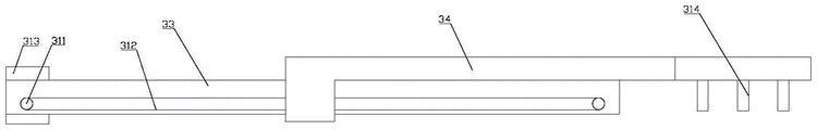
As shown in fig. 3, the first power mechanism has a structure that: two ends of the first cross arm 33 are provided with a transmission shaft 311, the axial direction of the transmission shaft 311 is vertical to the sliding direction of the second cross arm 34 on the first cross arm 33, a synchronous belt 312 is wound on the two transmission shafts 311, the second cross arm 34 is fixedly connected with one part of the synchronous belt 312, the first cross arm 33 is provided with a third motor 313, and the third motor 313 is in transmission connection with one transmission shaft 311. Through the arrangement of the two transmission shafts 311 on the first cross arm 33 and the synchronous belt 312 wound on the transmission shafts 311, and the second cross arm 34 is fixed on the synchronous belt 312, the second cross arm 34 can be driven to slide on the first cross arm 33 when the third motor 313 drives the synchronous belt 312 to move. The third motor 313 may be a servo motor, which can precisely control the control distance of the second cross arm 34 on the first cross arm 33, and the motion is fast and stable.
The adsorption mechanism 35 on the mechanical arm 3 between the discharging table 1 and the punching machine 2 is a sucker, and the adsorption mechanisms 35 on the other mechanical arms 3 are electromagnets 314. Because the work piece on the ejection of compact platform 1 is circular sheetmetal, its surfacing, so adopt the sucking disc, the negative pressure is connected to the sucking disc, utilizes the negative pressure to adsorb the circular sheetmetal at the top, and can adsorb only a slice, so the reliability is high. However, if the electromagnet 314 is used for attraction, the magnetism is transferred downward, and thus monolithic attraction cannot be realized. In addition, the surface of the workpiece after stamping is not a flat plane, so the workpiece is adsorbed by the electromagnet 314 and can be adsorbed alone, the adsorption is firm and stable, and if a sucker is adopted, the adsorption surface is uneven, the adsorption force is poor and the stability is low.
As shown in fig. 4, the discharging table 1 has the following structure: the automatic stacking machine comprises a frame 11, wherein a first guide rod 12 is horizontally arranged on the frame 11, a material rest 13 is connected on the first guide rod 12 in a sliding manner, raw materials are stacked on the material rest 13, the frame 11 extends to the position above the material rest 13 from the position below the material rest 13, a second guide rod 14 is arranged on the frame 11 above the material rest 13, a sliding seat 15 is arranged on the second guide rod 14, a vertical downward air cylinder 16 is arranged on the sliding seat 15, a suction disc 17 is arranged at the end part of an expansion link of the air cylinder 16, a transfer platform 18 is arranged on the frame 11 below one end of the second guide rod 14, a third power mechanism (not shown in fig. 4) is arranged between the material rest 13 and the frame 11, and a fourth power mechanism (not shown in fig. 4) is arranged between the second guide rod 14 and the frame 11.
Above-mentioned scheme, in order to once only to increase blowing quantity, ejection of compact platform 1 adopts the mobilizable form of work or material rest, arranges many piles of circular sheetmetal on work or material rest 13, by cylinder 16 flexible in-process on the sliding seat 15 adsorbs circular sheetmetal to transfer platform 18 one by one to make ejection of compact platform 1 and the first punching press arm 3 between 2 get the material position stable. In addition, the third power mechanism and the fourth power mechanism may be a combination of a screw 39 nut and a motor, the motor and the screw 39 are arranged on the frame, the nut is fixed on the rack 14 and the sliding seat 15, the screw 39 drives the rack 14 to move on the first guide bar 12, and drives the sliding seat 15 to move on the second guide bar 14.
In the description of the present application, it is to be understood that the terms "center," "longitudinal," "lateral," "length," "width," "thickness," "upper," "lower," "front," "rear," "left," "right," "vertical," "horizontal," "top," "bottom," "inner," "outer," "clockwise," "counterclockwise," and the like are used in the orientations and positional relationships indicated in the drawings for convenience in describing the present application and for simplicity in description, and are not intended to indicate or imply that the referenced devices or elements must have a particular orientation, be constructed in a particular orientation, and be operated in a particular manner, and are not to be construed as limiting the present application. Furthermore, the terms "first", "second" and "first" are used for descriptive purposes only and are not to be construed as indicating or implying relative importance or implicitly indicating the number of technical features indicated. Thus, a feature defined as "first" or "second" may explicitly or implicitly include one or more of that feature. In the description of the present application, "a plurality" means two or more unless specifically limited otherwise.
In the description of the present application, it is to be noted that, unless otherwise explicitly specified or limited, the terms "mounted," "connected," and "connected" are to be construed broadly, e.g., as meaning either a fixed connection, a removable connection, or an integral connection; may be a mechanical connection; they may be directly connected or indirectly connected through intervening media, or may be in the interactive relationship of two elements. The specific meaning of the above terms in the present application can be understood by those of ordinary skill in the art as appropriate.
In this application, unless expressly stated or limited otherwise, the first feature "on" or "under" the second feature may comprise direct contact of the first and second features, or may comprise contact of the first and second features not directly but through another feature in between. Also, the first feature being "on," "above" and "over" the second feature includes the first feature being directly on and obliquely above the second feature, or merely indicating that the first feature is at a higher level than the second feature. A first feature being "under," "below," and "beneath" a second feature includes the first feature being directly under and obliquely below the second feature, or simply meaning that the first feature is at a lesser elevation than the second feature.
Although the present invention has been described with reference to the preferred embodiments, it will be understood by those skilled in the art that various changes may be made and equivalents may be substituted for elements thereof without departing from the scope of the present invention.
Claims (5)
1. A continuous stamping production equipment for a front cover of a brake is characterized in that: the punching machine comprises a discharging table, a plurality of punching machine tools and a collecting box, wherein the punching machine tools are arranged in a row between the discharging table and the collecting box, mechanical arms are arranged between the discharging table and the adjacent punching machine tools, between the adjacent two punching machine tools and between the collecting box and the adjacent punching machine tools, and the mechanical arms transfer workpieces of a previous process to a next process; the structure of the mechanical arm is as follows: the automatic workpiece adsorption device comprises a base and a connecting column arranged on the base, wherein a first cross arm is fixed at the top of the connecting column, a second cross arm is connected to the first cross arm in a sliding mode, a first power mechanism is arranged between the first cross arm and the second cross arm, an adsorption mechanism used for adsorbing workpieces is arranged at the end portion of the second cross arm, a second power mechanism is arranged inside the base, and the second power mechanism drives the connecting column to lift and rotate relative to the base.
2. The continuous press-producing apparatus for a front cover of a brake as claimed in claim 1, wherein: the structure of the second power mechanism is as follows: the sliding rail is arranged in the base in the vertical direction, a sliding block is arranged on the sliding rail, the lower end of the connecting column is connected with the sliding block in a rotating mode, a first motor is arranged on the sliding block and connected with the connecting column in a transmission mode, a screw hole is formed in the sliding block, a lead screw penetrates through the screw hole, the lead screw is arranged in the vertical direction, the lead screw is connected with the base in a rotating mode, a second motor is arranged at one end of the lead screw, and the second motor is connected with the lead screw in a transmission mode.
3. The continuous press-producing apparatus for a front cover of a brake as claimed in claim 1 or 2, wherein: the structure of the first power mechanism is as follows: two ends of the first cross arm are provided with a transmission shaft, the axial direction of the transmission shaft is vertical to the sliding direction of the second cross arm on the first cross arm, a synchronous belt is wound on the two transmission shafts, the second cross arm is fixedly connected with one part of the synchronous belt, the first cross arm is provided with a third motor, and the third motor is in transmission connection with one of the transmission shafts.
4. The continuous press-producing apparatus for a front cover of a brake as claimed in claim 3, wherein: the adsorption mechanism on the mechanical arm between the discharging table and the punching machine tool is a sucker, and the adsorption mechanisms on the other mechanical arms are electromagnets.
5. The continuous press-producing apparatus for a front cover of a brake as claimed in claim 1, wherein: the structure of the discharging table is as follows: the automatic stacking machine comprises a frame, wherein a first guide rod is horizontally arranged on the frame, a material rack is connected to the first guide rod in a sliding mode, raw materials are stacked on the material rack, the frame extends to the upper portion of the material rack from the lower portion of the material rack, a second guide rod is arranged on the frame above the material rack, a sliding seat is arranged on the second guide rod, a vertical downward air cylinder is arranged on the sliding seat, a sucking disc is arranged at the end portion of a telescopic rod of the air cylinder, a transfer platform is arranged on the frame below one end of the second guide rod, a third power mechanism is arranged between the material rack and the frame, and a fourth power mechanism is arranged between the second guide rod and the frame.
Priority Applications (1)
| Application Number | Priority Date | Filing Date | Title |
|---|---|---|---|
| CN202123453209.8U CN216632254U (en) | 2021-12-31 | 2021-12-31 | Continuous stamping production equipment for front cover of brake |
Applications Claiming Priority (1)
| Application Number | Priority Date | Filing Date | Title |
|---|---|---|---|
| CN202123453209.8U CN216632254U (en) | 2021-12-31 | 2021-12-31 | Continuous stamping production equipment for front cover of brake |
Publications (1)
| Publication Number | Publication Date |
|---|---|
| CN216632254U true CN216632254U (en) | 2022-05-31 |
Family
ID=81724644
Family Applications (1)
| Application Number | Title | Priority Date | Filing Date |
|---|---|---|---|
| CN202123453209.8U Active CN216632254U (en) | 2021-12-31 | 2021-12-31 | Continuous stamping production equipment for front cover of brake |
Country Status (1)
| Country | Link |
|---|---|
| CN (1) | CN216632254U (en) |
Cited By (1)
| Publication number | Priority date | Publication date | Assignee | Title |
|---|---|---|---|---|
| CN117003181A (en) * | 2023-06-27 | 2023-11-07 | 全椒亮克威泽工业涂料有限公司 | Automatic change thick paint vehicle and transport bucket closing cap system |
-
2021
- 2021-12-31 CN CN202123453209.8U patent/CN216632254U/en active Active
Cited By (1)
| Publication number | Priority date | Publication date | Assignee | Title |
|---|---|---|---|---|
| CN117003181A (en) * | 2023-06-27 | 2023-11-07 | 全椒亮克威泽工业涂料有限公司 | Automatic change thick paint vehicle and transport bucket closing cap system |
Similar Documents
| Publication | Publication Date | Title |
|---|---|---|
| CN109692992B (en) | Automatic production device for fine shearing of automobile steel plates | |
| CN109264398B (en) | Automatic feeding device for lens processing | |
| CN109079047B (en) | Automatic feeding and discharging equipment of stamping robot | |
| CN209157444U (en) | Welding packing production line grasping mechanism | |
| CN211768395U (en) | Automatic feeding equipment | |
| CN111532799A (en) | Bottom sucker separating machine | |
| CN216632254U (en) | Continuous stamping production equipment for front cover of brake | |
| CN206702737U (en) | A kind of fully automatic feeding equipment | |
| JPH0441029A (en) | Method and device for selecting and integrating many numbers of small products | |
| CN113400414B (en) | CCD positioning full-automatic sheet machine | |
| CN220392625U (en) | Unstacking and feeding equipment for U-shaped section bar | |
| CN109848285B (en) | Four-axis planar robot integrated system for automatic feeding and discharging of high-speed notching press | |
| CN215919855U (en) | Discharging manipulator | |
| CN216397693U (en) | Motor silicon steel sheet notching production line | |
| CN212884627U (en) | Go up unloading automation equipment | |
| CN109047398A (en) | A kind of sheet fabrication center | |
| CN209792456U (en) | Automatic feeder for sheet stock of punch press | |
| CN205110479U (en) | Full -automatic key embryo punching machine | |
| CN212760779U (en) | Automatic stamping equipment of roof with feed mechanism | |
| CN211682491U (en) | Visual punching machine | |
| CN208960688U (en) | A kind of sheet fabrication center | |
| CN210236368U (en) | Auto parts workstation with automatic pile up neatly function | |
| CN113490127B (en) | Automatic fixed point copper foil production facility of taking paper of stereo set coil processing | |
| CN214988632U (en) | Short plate transmission device | |
| CN217192162U (en) | Automatic stamping forming production system for automobile transmission suspension support parts |
Legal Events
| Date | Code | Title | Description |
|---|---|---|---|
| GR01 | Patent grant | ||
| GR01 | Patent grant |