CN216580490U - Transport trolley device suitable for large-scale pressure steel pipe - Google Patents
Transport trolley device suitable for large-scale pressure steel pipe Download PDFInfo
- Publication number
- CN216580490U CN216580490U CN202123063440.6U CN202123063440U CN216580490U CN 216580490 U CN216580490 U CN 216580490U CN 202123063440 U CN202123063440 U CN 202123063440U CN 216580490 U CN216580490 U CN 216580490U
- Authority
- CN
- China
- Prior art keywords
- trolley device
- pressure steel
- transportation
- transverse frame
- hole
- Prior art date
- Legal status (The legal status is an assumption and is not a legal conclusion. Google has not performed a legal analysis and makes no representation as to the accuracy of the status listed.)
- Active
Links
Images


Landscapes
- Handcart (AREA)
Abstract
The utility model provides a transportation trolley device suitable for large-scale pressure steel pipes, belongs to the technical field of large-scale pressure steel pipe transportation, and solves the problem that different types of transportation trolleys are required to be designed to adapt to the transportation of pressure steel pipes with different pipe diameters at present, so that the cost is not favorably controlled. This transportation trolley device suitable for large-scale pressure steel pipe, including first horizontal frame, frame and fixed establishment, the fixed second horizontal frame that is provided with between the frame of both sides, the inboard of the horizontal frame of second is provided with the fixed block, and the both sides of fixed block bottom are all bolted connection to have the curb plate. The trolley device has a simple design structure, is convenient for workers to disassemble or assemble, has the advantage of low price, reduces the design cost, is suitable for transportation with different pipe diameters, and can push away small obstacles such as stones and the like on the track through the inclined block in the advancing process of the trolley device so as to prevent the roller of the trolley device from pressing the obstacles and avoid derailing or overturning of the trolley device.
Description
Technical Field
The utility model belongs to the technical field of large-scale pressure steel pipe transportation, and relates to a transportation trolley device, in particular to a transportation trolley device suitable for large-scale pressure steel pipes.
Background
Along with the diameter of the underground buried large-scale pressure steel pipe is larger and larger, installation also faces a plurality of technical problems, transportation in a steel pipe hole is the first considered problem, at present, transportation trolleys are generally adopted for transportation, unloading and installation construction of the pressure steel pipe in the inclined section, the inclined shaft and the flat section of the hydropower station, and the design of the transportation trolleys is multiple and various.
In order to ensure the stability and deformation factors of the pressure steel pipes during transportation, different types of transportation trolleys need to be equipped in the trolley design due to overlarge pipe diameter difference of the pressure steel pipes, namely trolleys with different wheel pitches and lengths are designed according to the pipe diameters of the steel pipes, and if the pressure steel pipes are greatly different in engineering, the trolleys for transporting the large reducing steel pipes need to be redesigned and manufactured so as to ensure the normal installation and safe transportation of the pressure steel pipes with different pipe diameters, and the control cost is not favorable. In addition, along with the higher and higher specialization degree of the installation and transportation of the pressure steel pipes, the steel pipe installation and construction of other projects are started after the projects are finished, the trolley is complex in design, expensive to manufacture and long in time consumption, small stones and other obstacles on the track exist in the moving process of the trolley, once the small stones and other obstacles are pressed by the trolley, the possibility of derailment and even overturning can exist, and the potential safety hazard is large.
SUMMERY OF THE UTILITY MODEL
The utility model aims to solve the problems in the prior art, and provides a transportation trolley device suitable for large-sized pressure steel pipes, which has the advantages of simple design structure, convenience in disassembly and assembly, low price and suitability for transportation with different pipe diameters, and can push away small obstacles such as stones in the advancing process, so that the phenomenon of derailment or overturning of the device is avoided.
The purpose of the utility model can be realized by the following technical scheme:
the utility model provides a transportation platform truck device suitable for large-scale pressure steel pipe, includes first horizontal frame, frame and fixed establishment, the fixed horizontal frame of second that is provided with between the frame of both sides, the inboard of the horizontal frame of second is provided with the fixed block, the both sides of fixed block bottom all bolted connection have the curb plate, the surface of curb plate runs through and is provided with the smooth axle sleeve, the one side that the curb plate is relative is provided with the gyro wheel, and the gyro wheel is fixed mutually with the inner circle of smooth axle sleeve, the top of the horizontal frame of second is provided with the base, both sides are all fixed around the base top and are provided with the support frame, the fixed locating plate that is provided with in one side that the support frame is relative of both sides, the fixed connecting plate that is provided with in front of first horizontal frame, the fixed sloping block that is provided with in front of connecting plate, the surface of sloping block runs through and has seted up logical groove.
The working principle of the utility model is as follows: arrange base and support frame in the top of the horizontal frame of second, use the gasket to carry out altitude mixture control, later pass first through-hole and second through-hole in proper order with fixing bolt and fix the support frame in the top of platform truck, then use the loop wheel machine to hoist large-scale penstock to the top of support frame, the support frame supports the steel pipe, the platform truck walks on the track face, there is less clearance at the inner wall that leads to the groove and orbital surface, and the sloping block then can push away the small stone on track surface or other small-size barriers, thereby avoid the gyro wheel to press.
The fixing mechanism comprises a first through hole, a second through hole, a fixing bolt and a fixing nut, the first through hole penetrates through the surface of the base, and the second through hole penetrates through the surface of the second transverse frame.
The structure is used for fixing the base and the support frame on the second transverse frame, so that the purpose of assembling the support frame and the trolley is achieved.
And a square inclined washer is arranged on the surface of the fixing bolt and is in contact with the surface of the second transverse frame.
By adopting the structure, the square inclined washer enables the fixing nut to be difficult to rotate under the action of friction force, and is used for preventing the fixing nut from loosening to cause the fixing bolt to fall off.
The front of the first transverse frame is fixedly provided with a traction piece, and a round hole is formed in the surface of the traction piece in a penetrating mode.
Structure more than adopting, through the setting of pulling piece and round hole, pass the haulage rope and link to each other with traction equipment in the inside of round hole, alright use traction equipment to stimulate this platform truck device and remove.
The traction piece is fixed with the surface of the first transverse frame in a welding mode, and the inner diameter of the round hole is 8-20 mm.
By adopting the design, the traction rope can penetrate through the round hole.
The connecting plate is fixed with the first transverse frame in a bolting mode, and the inclination angle of the inclined block is 30-45 degrees.
By adopting the design, the inclined block can be detached so as to be convenient to replace.
Compared with the prior art, this transportation platform truck device suitable for large-scale penstock has following advantage:
1. the trolley device has a simple design structure, is convenient for workers to disassemble or assemble, has the advantage of low price, reduces the design cost, and is suitable for transportation with different pipe diameters, small obstacles such as stones on a track can be pushed away by the inclined block in the advancing process of the trolley device, so that the self roller is prevented from pressing the obstacles, the phenomenon of derailment or overturning of the device is avoided, and the problem that the current trolley device is not favorable for controlling the cost because different types of transportation trolleys are required to be designed to adapt to transportation of pressure steel pipes with different pipe diameters is solved.
2. Through first through-hole, second through-hole, fixing bolt and fixation nut, pass first through-hole and second through-hole with fixing bolt in proper order to rotatory fixing bolt, alright fix the base on the horizontal frame of second, thereby realize the effect of assembling support frame and platform truck each other, also can dismantle simultaneously.
3. Through the setting of pulling piece and round hole, pass the haulage rope and link to each other with traction equipment in the inside of round hole, alright use traction equipment to stimulate this platform truck device and remove.
Drawings
Fig. 1 is a schematic perspective view of the present invention.
Fig. 2 is a partial front sectional structure diagram of the present invention.
Fig. 3 is a schematic perspective view of the frame of the present invention.
Fig. 4 is a partial bottom view of the present invention.
Fig. 5 is an enlarged view of a portion a of fig. 2 according to the present invention.
Fig. 6 is a perspective view of a part of the components of the present invention.
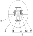
In the figure, 1, a first transverse frame; 2. a frame; 3. a second transverse frame; 4. a fixed block; 5. a side plate; 6. a sliding shaft sleeve; 7. a roller; 8. a base; 9. a fixing mechanism; 91. a first through hole; 92. a second through hole; 93. fixing the bolt; 94. fixing a nut; 10. a support frame; 11. positioning a plate; 12. a connecting plate; 13. a sloping block; 14. a through groove; 15. a traction member; 16. a circular hole; 17. a square bevel washer.
Detailed Description
The following are specific embodiments of the present invention and are further described with reference to the drawings, but the present invention is not limited to these embodiments.
As shown in fig. 1-6, the transportation trolley device suitable for large-scale pressure steel pipes comprises a first transverse frame 1, two sets of frames 2 and a fixing mechanism 9, wherein the two sets of frames 2 are arranged in a left-right manner, a second transverse frame 3 is fixedly arranged between the frames 2 at two sides, a fixing block 4 is arranged at the inner side of the second transverse frame 3, side plates 5 are bolted at two sides of the bottom of the fixing block 4, a sliding shaft sleeve 6 is arranged on the surface of each side plate 5 in a penetrating manner, a roller 7 is arranged at one side opposite to the side plate 5, the roller 7 is fixed with an inner ring of the sliding shaft sleeve 6, a base 8 is arranged above the second transverse frame 3, supporting frames 10 are fixedly arranged at the front side and the rear side of the top of the base 8, the whole supporting frames 10 are in an arc-shaped design and are used for fitting steel pipes, a positioning plate 11 is fixedly arranged at one side opposite to the supporting frames 10 at two sides, a connecting plate 12 is fixedly arranged at the front of the first transverse frame 1, the fixed sloping block 13 that is provided with in front side of connecting plate 12, logical groove 14 has been seted up in the surface run-through of sloping block 13, the device design simple structure, the staff of being convenient for dismantles or assembles, the device has low price's advantage simultaneously, and reduce design cost, it is applicable in the transportation of different pipe diameters, and this platform truck device is pushing away small-size barriers such as the stone on the track at the in-process accessible sloping block 13 that gos forward, press the barrier with self gyro wheel 7, the phenomenon of derailment or turnover appears in avoiding device itself, the transportation of pressure steel pipe for adapting to different pipe diameters at present has been solved, often need design different grade type transportation platform truck, thereby be unfavorable for control cost's problem.
The surface of the fixing bolt 93 is provided with a square washer 17, and the square washer 17 is in contact with the surface of the second transverse frame 3, and in the embodiment, through the arrangement of the square washer 17, the square washer can act on the surfaces of the fixing bolt 93 and the fixing nut 94, and the fixing nut 94 is not easy to rotate under the action of friction force, so that the fixing nut 94 is prevented from falling off.
The fixed tractive piece 15 that is provided with in front of first transverse frame 1, the surface of tractive piece 15 runs through and has seted up round hole 16, in this embodiment, through the setting of tractive piece 15 and round hole 16, passes the haulage rope and links to each other with traction equipment in the inside of round hole 16, alright use traction equipment pulling this platform truck device to remove.
The traction piece 15 is fixed on the surface of the first transverse frame 1 by welding, the inner diameter of the round hole 16 is 8-20mm, and in the embodiment, the design is adopted to avoid that the diameter of the round hole 16 is too small to lead the traction rope to pass through.
The connecting plate 12 is fixed mutually with first horizontal frame 1 through the mode of bolt, and the inclination of sloping block 13 is 30-45, and the material of sloping block 13 is wear-resisting steel, and is more wear-resisting, in this embodiment, through design connecting plate 12 and first horizontal frame 1 bolt, it makes connecting plate 12 and sloping block 13 can with first horizontal frame 1 between dismantle, makes things convenient for the staff to change the sloping block 13 of damage.
The working principle of the utility model is as follows: when in use, the device is firstly connected with traction equipment, the base 8 and the support frame 10 are arranged above the second transverse frame 3, then the base 8 is cushioned by using a gasket to adjust the height, so that the device can be suitable for transportation with different pipe diameters, then the fixing bolt 93 sequentially passes through the first through hole 91 and the second through hole 92 to be fixed, at the moment, the base 8 and the support frame 10 are fixed above the trolley, then a crane is used for hoisting a large-sized pressure steel pipe to the upper part of the support frame 10, the support frame 10 is matched with the steel pipe through the arc surface of the support frame to prevent the steel pipe from moving left and right, then the trolley device runs on the upper surface of the rail through the roller 7, in the running process, a small gap exists between the inner wall of the through groove 14 and the surface of the rail, and the inclined block 13 can push small stones or other small obstacles on the surface of the rail away, so as to avoid the roller 7 from being pressed, the safety of the device is improved, and when the trolley reaches the position where the steel pipe is installed, the trolley is stopped to hang down the steel pipe.
The specific embodiments described herein are merely illustrative of the spirit of the utility model. Various modifications or additions may be made to the described embodiments or alternatives may be employed by those skilled in the art without departing from the spirit or ambit of the utility model as defined in the appended claims.
Claims (6)
1. A transportation trolley device suitable for large-scale pressure steel pipes comprises a first transverse frame (1), frames (2) and a fixing mechanism (9), and is characterized in that a second transverse frame (3) is fixedly arranged between the frames (2) on two sides, a fixing block (4) is arranged on the inner side of the second transverse frame (3), side plates (5) are bolted on two sides of the bottom of the fixing block (4), a sliding shaft sleeve (6) penetrates through the surface of each side plate (5), rollers (7) are arranged on one side, opposite to the side plates (5), of each roller (7) are fixed with the inner ring of the corresponding sliding shaft sleeve (6), a base (8) is arranged above the second transverse frame (3), support frames (10) are fixedly arranged on the front side and the rear side of the top of the base (8), and a positioning plate (11) is fixedly arranged on one side, opposite to the support frames (10) on two sides, the front face of the first transverse frame (1) is fixedly provided with a connecting plate (12), the front side of the connecting plate (12) is fixedly provided with an inclined block (13), and the surface of the inclined block (13) is provided with a through groove (14) in a penetrating mode.
2. A transportation trolley device suitable for large-scale pressure steel pipes according to claim 1, characterized in that the fixing mechanism (9) comprises a first through hole (91), a second through hole (92), a fixing bolt (93) and a fixing nut (94), the first through hole (91) is arranged on the surface of the base (8) in a penetrating way, and the second through hole (92) is arranged on the surface of the second transverse frame (3) in a penetrating way.
3. A transporting trolley device suitable for large-scale pressure steel pipes according to claim 2 characterized in that the surface of the fixing bolt (93) is provided with a square washer (17), and the square washer (17) is in contact with the surface of the second transverse frame (3).
4. The transportation trolley device suitable for the large-sized pressure steel pipe is characterized in that a traction piece (15) is fixedly arranged on the front surface of the first transverse frame (1), and a circular hole (16) is formed in the surface of the traction piece (15) in a penetrating mode.
5. A transportation trolley device suitable for large-scale pressure steel pipes according to claim 4 is characterized in that the traction piece (15) is fixed with the surface of the first transverse frame (1) through welding, and the inner diameter of the round hole (16) is 8-20 mm.
6. A trolley device for transporting large-sized pressure steel pipes according to claim 1, characterized in that the connecting plate (12) is fixed with the first transverse frame (1) by bolting, and the angle of inclination of the sloping block (13) is 30-45 °.
Priority Applications (1)
| Application Number | Priority Date | Filing Date | Title |
|---|---|---|---|
| CN202123063440.6U CN216580490U (en) | 2021-12-07 | 2021-12-07 | Transport trolley device suitable for large-scale pressure steel pipe |
Applications Claiming Priority (1)
| Application Number | Priority Date | Filing Date | Title |
|---|---|---|---|
| CN202123063440.6U CN216580490U (en) | 2021-12-07 | 2021-12-07 | Transport trolley device suitable for large-scale pressure steel pipe |
Publications (1)
| Publication Number | Publication Date |
|---|---|
| CN216580490U true CN216580490U (en) | 2022-05-24 |
Family
ID=81610459
Family Applications (1)
| Application Number | Title | Priority Date | Filing Date |
|---|---|---|---|
| CN202123063440.6U Active CN216580490U (en) | 2021-12-07 | 2021-12-07 | Transport trolley device suitable for large-scale pressure steel pipe |
Country Status (1)
| Country | Link |
|---|---|
| CN (1) | CN216580490U (en) |
-
2021
- 2021-12-07 CN CN202123063440.6U patent/CN216580490U/en active Active
Similar Documents
| Publication | Publication Date | Title |
|---|---|---|
| CN202345727U (en) | Flat-plate transport trolley | |
| CN203269274U (en) | Slope section rail type conveying device | |
| CN203496955U (en) | Movable type lifting trolley | |
| CN105540143A (en) | Simple trash can lifting frame | |
| CN103527243A (en) | Incline hoist transportation system for subway construction and setup method thereof | |
| CN101992990B (en) | Double-inclined-way traction elevator | |
| CN205895274U (en) | A section of jurisdiction travelling bogie that is used for shield constituent body to start | |
| CN113335317B (en) | Monorail track roof beam fortune frame mobile device in tunnel | |
| CN204739326U (en) | Steel truss or piping lane gallows poling auxiliary device | |
| CN216580490U (en) | Transport trolley device suitable for large-scale pressure steel pipe | |
| CN201240315Y (en) | Freely steering transportation flat car | |
| CN205805587U (en) | A kind of Miniature portable section of jurisdiction flat bed transport vehicle | |
| CN112937417A (en) | Pipeline unloading device, system and method | |
| CN112079066A (en) | Large-scale transformer is from running gear | |
| CN201457377U (en) | Monorail crane load bearing trolley | |
| CN110626733A (en) | Special device for transporting ultra-large-diameter pipeline in narrow space | |
| CN116495501A (en) | Train container unloading system and unloading method | |
| CN111006068A (en) | Large steel pipe transportation welding alignment tool car and use method thereof | |
| CN215854729U (en) | Gantry crane for high-speed rail | |
| CN212333788U (en) | Large-scale transformer is from running gear | |
| CN209795521U (en) | Steel pipe travelling bogie with lifting and steering device | |
| CN213057073U (en) | Inclined shaft expands digs manned trolley anti-derailment device | |
| CN109532981B (en) | Subway tunnel interval cable laying and transporting device | |
| CN210418998U (en) | Conveying device for large-diameter pipeline of circulating water system | |
| CN204506903U (en) | Rail transport quick despatch car device |
Legal Events
| Date | Code | Title | Description |
|---|---|---|---|
| GR01 | Patent grant | ||
| GR01 | Patent grant |