CN216377260U - Material lifting device - Google Patents
Material lifting device Download PDFInfo
- Publication number
- CN216377260U CN216377260U CN202122596574.8U CN202122596574U CN216377260U CN 216377260 U CN216377260 U CN 216377260U CN 202122596574 U CN202122596574 U CN 202122596574U CN 216377260 U CN216377260 U CN 216377260U
- Authority
- CN
- China
- Prior art keywords
- lifting device
- material lifting
- movable groove
- operation platform
- feeding notch
- Prior art date
- Legal status (The legal status is an assumption and is not a legal conclusion. Google has not performed a legal analysis and makes no representation as to the accuracy of the status listed.)
- Active
Links
- 230000002093 peripheral effect Effects 0.000 claims description 3
- 238000009435 building construction Methods 0.000 description 2
- 238000010276 construction Methods 0.000 description 2
- 230000000694 effects Effects 0.000 description 2
- 238000012840 feeding operation Methods 0.000 description 2
- 230000009286 beneficial effect Effects 0.000 description 1
- 230000007547 defect Effects 0.000 description 1
Images


Landscapes
- Invalid Beds And Related Equipment (AREA)
Abstract
The utility model discloses a material lifting device which comprises a hoist and a supporting seat, wherein an operation platform is arranged above the supporting seat through a lifting mechanism, and the right end part of the operation platform is provided with a feeding notch; a support is fixedly arranged above the feeding notch, the right end of the support extends outwards, a first slide rod and a first screw rod connected with a driving motor in a power mode are horizontally arranged below the top surface of the support, and the hoist is arranged on the connecting frame; the upper end of the connecting frame is sleeved with the sliding rod in a sliding manner and is sleeved with the screw in a threaded manner; the inner side of the feeding notch is provided with a movable groove, and a supporting plate which is controlled by an adjusting mechanism and can extend outwards is arranged in the movable groove. The utility model aims to provide a material lifting device which is convenient to feed and saves time and labor for lifting materials.
Description
Technical Field
The utility model belongs to the field of building construction equipment, and particularly relates to a material lifting device.
Background
In building construction, materials are often required to be lifted to a high place for operation. The existing material lifting device is generally provided with a feeding port in the middle of a construction platform, and the volume of the lifted material is limited by the size of the feeding port, so that the construction is inconvenient. And after the existing lifting device lifts the material to the upper part of the operation platform through the lifting rope, the material is still in a suspended state, and a worker needs to manually drag the material to the platform, so that time and labor are wasted, and potential safety hazards exist.
SUMMERY OF THE UTILITY MODEL
In order to solve the defects of the prior art, the utility model aims to provide the material lifting device which is convenient to feed and saves time and labor for lifting materials.
In order to achieve the purpose, the utility model adopts the technical scheme that:
a material lifting device comprises a hoist and a supporting seat, wherein an operation platform is arranged above the supporting seat through a lifting mechanism, and a feeding notch is formed in the right end part of the operation platform; a support is fixedly arranged above the feeding notch, the right end of the support extends outwards, a first slide rod and a first screw rod connected with a driving motor in a power mode are horizontally arranged below the top surface of the support, and the hoist is arranged on the connecting frame; the upper end of the connecting frame is sleeved with the sliding rod in a sliding manner and is sleeved with the screw in a threaded manner; the inner side of the feeding notch is provided with a movable groove, and a supporting plate which is controlled by an adjusting mechanism and can extend outwards is arranged in the movable groove.
Preferably, the bottom of the supporting plate is connected with the bottom of the movable groove through a sliding rail.
Preferably, a second slide bar and a second screw rod are arranged in parallel on the inner side of the movable groove far away from the opening, two moving blocks are sleeved at one end of the second screw rod in a threaded manner, and the other end of the second screw rod is connected with the adjusting mechanism; the two moving blocks are sleeved with the second sliding rod in a sliding manner; the end part of the support plate in the movable groove is provided with two movable rods which are arranged in a crossed manner, one end parts of the two movable rods are hinged to the support plate, the middle parts of the two movable rods are connected together in a rotating manner, and the other ends of the two movable rods are hinged to the corresponding movable blocks respectively.
Preferably, the adjusting mechanism comprises a shell, a crank and a gear, the shell is installed above the operation platform, the crank arranged outside penetrates through the shell and is fixedly connected with the gear in the shell in a concentric mode, and the gear penetrates through the operation platform downwards and is meshed with the second screw.
Preferably, the opening of the movable groove is provided with a touch block, and a limit block matched with the touch block is fixedly arranged above the supporting plate.
Preferably, wear-resisting gaskets are arranged on the opening edge of the feeding notch and the outer edge of the supporting plate.
Preferably, guard railings are installed on the peripheral edge of the operation platform.
Preferably, a balancing weight is arranged on one side, away from the feeding notch, of the supporting seat.
The utility model has the following beneficial effects:
1. compared with the prior art that the material needs to be manually pulled onto the platform, the lifting device can enable the hoist to move in the horizontal direction through the matching of the first screw and the connecting rod, so that the material can be horizontally moved, the operation intensity of constructors is effectively reduced, and the material is lifted more time-saving and labor-saving. Meanwhile, the feeding notch is arranged, so that the feeding operation space can be effectively enlarged, the hoisting operation of large-volume materials is facilitated, and the feeding efficiency is improved.
2. The bottom of the supporting plate is connected with the bottom of the movable groove through the sliding rail, after the feeding is completed, the adjusting mechanism is controlled to move, the supporting plate can be extended out in an outward sliding mode, the feeding notch is closed and sealed, and the operation safety is improved.
3. When the supporting plate is required to extend out of the closed feeding notch, the crank is rotated to drive the second screw rod to rotate through the gear, so that the two moving blocks can move in opposite directions, and then the two moving rods push the supporting plate to extend outwards, and effective control over the supporting plate is achieved. During the material loading operation, only need can withdraw the movable trough with the backup pad through rotating the crank, simple and convenient, receive and release of backup pad is laborsaving high-efficient more.
4. The extension length of the supporting plate can be effectively limited by the cooperation of the limiting block and the contact block, the supporting plate is pulled out due to stress when the material is loaded, and the running stability of the device is effectively improved.
5. The opening border of material loading notch and the outer border department of backup pad all are equipped with wear-resisting gasket, and material loading notch and backup pad border collide with the material when effectively avoiding the material loading, and wear-resisting gasket can play effectual cushioning effect.
Drawings
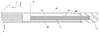
FIG. 1 is a schematic structural view of the present invention;
FIG. 2 is a top view of the work platform of the present invention;
FIG. 3 is a cross-sectional view of a work platform of the present invention;
fig. 4 is a schematic view of the connection of the support plates of the present invention.
Detailed Description
As shown in fig. 1-4, the present invention provides a material lifting device, which includes a hoist 4 and a support base 1, wherein an operation platform 2 is installed above the support base 1 through a lifting mechanism 12 (which may adopt a hydraulic cylinder), and a feeding notch 20 is formed inward at the right end of the operation platform 2. The support 3 is fixedly arranged above the feeding notch 20, the right end of the support 3 in the inverted L-shaped structure extends out of the operation platform 2, a first sliding rod 31 and a first screw 32 connected with the power of a driving motor are horizontally arranged below the top surface of the support 3, and the first sliding rod 31 plays a limiting role. The hoist 4 is arranged on the connecting frame 33, and the upper end of the connecting frame 33 is sleeved with the sliding rod in a sliding manner and is sleeved with the screw in a threaded manner. One side of the supporting seat 1 far away from the feeding notch 20 is provided with a balancing weight 11, so that the balancing weight is effectively improved, and the operation safety is ensured.
After the material is lifted to the upper part of the operation platform 2 by the lifting rope of the hoist 4, the driving motor is controlled to drive the first screw rod 32 to move, the connecting frame 33 drives the hoist 4 to move leftwards, and after the material is translated to the upper part of the middle part of the operation platform 2, the hoist 4 is controlled to place the material on the operation platform 2. Compared with the prior art that the material needs to be manually pulled to the platform, the lifting device can enable the hoist 4 to move in the horizontal direction through the matching of the first screw rod 32 and the connecting rod, so that the material can be horizontally moved, the operation intensity of constructors is effectively reduced, and the material is lifted more time-saving and labor-saving. Meanwhile, the feeding notch 20 is arranged, so that the feeding operation space can be effectively enlarged, the hoisting operation of large-volume materials is facilitated, and the feeding efficiency is improved.
A movable groove 23 is formed inwards in the feeding notch 20, and a supporting plate 5 which is controlled by an adjusting mechanism and can extend outwards is arranged in the movable groove 23. The bottom of the supporting plate 5 is connected with the bottom of the movable groove 23 through the sliding rail 51, and after the feeding is completed, the adjusting mechanism is controlled to act, so that the supporting plate 5 can slide outwards and extend out, the feeding notch 20 is closed and sealed, and the operation safety is improved.
Wherein, the inner side of the movable groove 23 far away from the opening is provided with a second slide bar 82 and a second screw 81 in parallel, the second screw 81 is rotatably installed in the movable groove 23, and one end of the second screw 81 is sleeved with two moving blocks 83. The two moving blocks 83 are sleeved on the second sliding rod 82 in a sliding manner, and the second sliding rod 82 plays a role in limiting sliding. The end of the support plate 5 in the movable groove 23 is provided with two X-shaped and cross-arranged movable rods 84, the left ends of the two movable rods 84 are hinged on the support plate 5, the middle parts are rotatably connected together, and the right ends are respectively hinged on the corresponding movable blocks 83. The adjusting mechanism comprises a shell 70, a crank 71 and a gear, the shell 70 is installed above the operation platform 2, the crank 71 arranged outside penetrates through the shell 70 to be concentrically and fixedly connected with the gear in the shell 70, and the gear penetrates through the operation platform 2 downwards to be meshed with the other end of the second screw 81. When the supporting plate 5 needs to extend out of the closed feeding notch 20, the rotating crank 71 drives the second screw 81 to rotate through the gear, so that the two moving blocks 83 can move towards each other, and then the two moving rods 84 push the supporting plate 5 to extend out, thereby realizing effective control of the supporting plate 5. During the material loading operation, only need can withdraw movable tank 23 with backup pad 5 through rotating crank 71, simple and convenient, the receive and release of backup pad 5 is laborsaving high-efficient more.
Wherein, the opening of the movable groove 23 is provided with a contact block 231, and a limit block 52 matched with the contact block 231 is fixedly arranged above the supporting plate 5. The extension length of the supporting plate 5 can be effectively limited by the matching of the limiting block 52 and the abutting block 231, the supporting plate 5 is pulled out outwards under the stress when the feeding is prevented, and the running stability of the device is effectively improved.
The opening border of material loading notch 20 and the outer border department of backup pad 5 all are equipped with wear-resisting gasket 6, and material colliding with in material loading notch 20 and the 5 borders of backup pad when effectively avoiding the material loading, wear-resisting gasket 6 can play effectual cushioning effect.
Claims (8)
1. The utility model provides a material lifting device, includes hoist and supporting seat, its characterized in that: an operation platform is arranged above the supporting seat through a lifting mechanism, and a feeding notch is formed in the right end of the operation platform; a support is fixedly arranged above the feeding notch, the right end of the support extends outwards, a first slide rod and a first screw rod connected with a driving motor in a power mode are horizontally arranged below the top surface of the support, and the hoist is arranged on the connecting frame; the upper end of the connecting frame is sleeved with the sliding rod in a sliding manner and is sleeved with the screw in a threaded manner; the inner side of the feeding notch is provided with a movable groove, and a supporting plate which is controlled by an adjusting mechanism and can extend outwards is arranged in the movable groove.
2. The material lifting device of claim 1, wherein: the bottom of the supporting plate is connected with the bottom of the movable groove through a sliding rail.
3. The material lifting device of claim 2, wherein: a second sliding rod and a second screw rod are arranged in parallel on the inner side of the movable groove far away from the opening, two moving blocks are sleeved at one end of the second screw rod in a threaded manner, and the other end of the second screw rod is connected with an adjusting mechanism; the two moving blocks are sleeved with the second sliding rod in a sliding manner; the end part of the support plate in the movable groove is provided with two movable rods which are arranged in a crossed manner, one end parts of the two movable rods are hinged to the support plate, the middle parts of the two movable rods are connected together in a rotating manner, and the other ends of the two movable rods are hinged to the corresponding movable blocks respectively.
4. A material lifting device as claimed in claim 3, wherein: the adjusting mechanism comprises a shell, a crank and a gear, the shell is installed above the operation platform, the crank arranged outside penetrates through the shell to be concentrically and fixedly connected with the gear in the shell, and the gear penetrates through the operation platform downwards to be meshed with the second screw.
5. The material lifting device of claim 1, wherein: the opening part of the movable groove is provided with a touch block, and a limit block matched with the touch block is fixedly arranged above the supporting plate.
6. The material lifting device of claim 1, wherein: wear-resisting gaskets are arranged at the opening edge of the feeding notch and the outer edge of the supporting plate.
7. The material lifting device of claim 1, wherein: guard railings are installed on the peripheral edge of the operation platform.
8. The material lifting device of claim 1, wherein: and a balancing weight is arranged on one side of the supporting seat, which is far away from the feeding notch.
Priority Applications (1)
| Application Number | Priority Date | Filing Date | Title |
|---|---|---|---|
| CN202122596574.8U CN216377260U (en) | 2021-10-27 | 2021-10-27 | Material lifting device |
Applications Claiming Priority (1)
| Application Number | Priority Date | Filing Date | Title |
|---|---|---|---|
| CN202122596574.8U CN216377260U (en) | 2021-10-27 | 2021-10-27 | Material lifting device |
Publications (1)
| Publication Number | Publication Date |
|---|---|
| CN216377260U true CN216377260U (en) | 2022-04-26 |
Family
ID=81246853
Family Applications (1)
| Application Number | Title | Priority Date | Filing Date |
|---|---|---|---|
| CN202122596574.8U Active CN216377260U (en) | 2021-10-27 | 2021-10-27 | Material lifting device |
Country Status (1)
| Country | Link |
|---|---|
| CN (1) | CN216377260U (en) |
-
2021
- 2021-10-27 CN CN202122596574.8U patent/CN216377260U/en active Active
Similar Documents
| Publication | Publication Date | Title |
|---|---|---|
| CN112900825B (en) | Well is from climbing operation platform | |
| CN108838954A (en) | A kind of novel and multifunctional mechanical equipment inspection rack device and its repair method | |
| CN208898444U (en) | It is a kind of to facilitate the fork truck bracket for loading weight | |
| CN208842449U (en) | It is a kind of large size paint can carrying and tilting device | |
| CN216377260U (en) | Material lifting device | |
| CN211169627U (en) | Lifting device for coal mine maintenance equipment | |
| CN204434117U (en) | A kind of balance crane assembling device | |
| CN217172978U (en) | Assembled construction hoist and mount side direction support system | |
| CN216276774U (en) | Lifting frame for building construction | |
| CN205772880U (en) | A kind of hanging balancing formula hoist crab | |
| CN112209283B (en) | Construction is with mechanical lifting means of operation of being convenient for | |
| CN212743292U (en) | Lifting device for housing construction | |
| CN219044808U (en) | Crane with adjustable arm length | |
| CN219217225U (en) | Be used for high-rise building installation pipeline safety hoist device | |
| CN206336980U (en) | One kind building lowering or hoisting gear | |
| CN111017739A (en) | Hoisting and transporting equipment capable of preventing goods from swinging | |
| CN210528308U (en) | Remove hoist and mount hoisting apparatus | |
| CN217535378U (en) | Novel construction elevator | |
| CN221160253U (en) | Movable overhauls platform | |
| CN210340071U (en) | Portable bridge cable duct apron lifting device | |
| CN213326476U (en) | Normally open type air hook quick release lifting mechanism | |
| CN217102802U (en) | Safe crane for building construction | |
| CN219683944U (en) | Vacuum ladle cleaning machine | |
| CN221370517U (en) | Lifting table for crane maintenance | |
| CN218371214U (en) | Rotary lifting appliance for lifting containers |
Legal Events
| Date | Code | Title | Description |
|---|---|---|---|
| GR01 | Patent grant | ||
| GR01 | Patent grant | ||
| TR01 | Transfer of patent right |
Effective date of registration: 20231115 Address after: No. 23-2 Weisi Road, North Industrial Park, Development Zone, Shihezi City, Xinjiang Uygur Autonomous Region, 832099 Patentee after: Xinjiang Tiantian Xiangshang Building Materials Co.,Ltd. Address before: 466000 room 1203, Merrill Lynch International, south section of Zhongzhou Road, Chuanhui District, Zhoukou City, Henan Province Patentee before: Henan Zhaolin Municipal Engineering Co.,Ltd. |
|
| TR01 | Transfer of patent right |