CN216188638U - Monorail crane transportation device - Google Patents
Monorail crane transportation device Download PDFInfo
- Publication number
- CN216188638U CN216188638U CN202122707306.9U CN202122707306U CN216188638U CN 216188638 U CN216188638 U CN 216188638U CN 202122707306 U CN202122707306 U CN 202122707306U CN 216188638 U CN216188638 U CN 216188638U
- Authority
- CN
- China
- Prior art keywords
- driving
- mounting plate
- fixedly arranged
- chain
- wheels
- Prior art date
- Legal status (The legal status is an assumption and is not a legal conclusion. Google has not performed a legal analysis and makes no representation as to the accuracy of the status listed.)
- Active
Links
Images


Landscapes
- Carriers, Traveling Bodies, And Overhead Traveling Cranes (AREA)
Abstract
The utility model belongs to the technical field of transportation equipment, and particularly relates to a monorail hoisting and conveying device which comprises a roadway, a left mounting plate and a right mounting plate, wherein a T-shaped rail is fixedly arranged on the inner wall of the top of the roadway, two vertical plates are fixedly arranged on the top of the right mounting plate, two rotating rods are rotatably arranged on the sides, close to each other, of the two vertical plates, and driving wheels are fixedly arranged at the inner ends of the four rotating rods. The utility model is convenient to adjust the space between the four moving wheels through the matching of the servo motor, the groove, the supporting plate, the bidirectional screw rod, the moving wheels, the driving chain wheel and the chain, is convenient to install on T-shaped rails with different widths, is convenient to disassemble, assemble, repair and maintain the crane, is convenient to hoist objects through the crane, the steel wire rope and the hook, and is convenient to drive the hoisted objects to be transported along the T-shaped rails through the matching of the driving motor, the driving shaft, the driving chain wheel, the driven chain wheel, the driving chain, the rotating rod, the driving wheel and the traction rod.
Description
Technical Field
The utility model relates to the technical field of transportation equipment, in particular to a single-rail hoisting and conveying device.
Background
The monorail crane auxiliary transportation system becomes main transportation equipment in developed countries with rich coal resources, and shows unique use effects: the cross section of the coal mine tunnel is more fully utilized, the material is saved, and no requirement is made on a tunnel bottom plate; the device can be suitable for a fluctuant roadway under the condition of small gradient (within 18 degrees); the turning radius is small, and the action is agile; from the above, the use effect is obviously superior to other mine auxiliary transportation devices, and in addition, the cost for early construction and later operation and maintenance is lower.
However, most of the existing monorail crane transportation devices are relatively fixed, the monorail crane transportation devices are inconvenient to adjust according to different widths of monorail tracks, and are inconvenient to install and disassemble, so that the monorail crane transportation devices are very inconvenient to use, and therefore the monorail crane transportation devices are provided for solving the problems.
SUMMERY OF THE UTILITY MODEL
The utility model aims to solve the defects that the existing monorail crane transportation device is mostly fixed, is inconvenient to adjust according to different widths of a monorail and is inconvenient to install and disassemble, so that the monorail crane transportation device is inconvenient to use.
In order to achieve the purpose, the utility model adopts the following technical scheme:
the single-rail hoisting and conveying device comprises a roadway, a left mounting plate and a right mounting plate, wherein a T-shaped track is fixedly arranged on the inner wall of the top of the roadway, two vertical plates are fixedly arranged on the top of the right mounting plate, one sides, close to each other, of the two vertical plates are respectively and rotatably provided with two rotary rods, the inner ends of the four rotary rods are respectively and fixedly provided with a driving wheel, the four driving wheels are respectively and rotatably connected onto the T-shaped track, driven sprockets are fixedly sleeved on the outer sides of the four rotary rods, a driving motor is fixedly arranged on the front side of the vertical plate positioned on the front side, a driving shaft is fixedly arranged on an output shaft of the driving motor, two driving sprockets are fixedly sleeved on the outer side of the driving shaft, the same transmission chain is respectively in transmission connection with the driving sprocket and the two driven sprockets positioned on the front side and the driving sprocket and the two driven sprockets positioned on the rear side, and the same traction rod is rotatably arranged between the left mounting plate and the right mounting plate, the fixed two cranes that are provided with in top of left side mounting panel, the bottom of crane is provided with wire rope, wire rope's bottom mounting is provided with the couple, two recesses have been seted up at the top of left side mounting panel, it is provided with same two-way lead screw to rotate on the front and back side inner wall of recess, and the rear end of two-way lead screws is all fixed and is provided with drive sprocket, and the transmission connection has same chain on two drive sprocket, the fixed servo motor that is provided with in front side of left side mounting panel, servo motor's the fixed two-way lead screw front end that sets up at the correspondence of output shaft, two backup pads have been cup jointed in the outside slip of two-way lead screw, and the inboard of four backup pads all rotates and is provided with the removal wheel, and four remove the equal roll connection of wheel on T type track.
Preferably, the bottom inner wall of the groove is provided with sliding grooves, the two sliding grooves are internally provided with four sliding plates in a sliding manner, and the four sliding plates are respectively and fixedly arranged at the bottoms of the corresponding supporting plates.
Preferably, the inner sides of the four supporting plates are all rotatably provided with rotating shafts, and the four movable wheels are respectively fixedly sleeved on the outer sides of the corresponding rotating shafts.
Preferably, the top of T type track is fixed with two jibs, and two jibs are all fixed to be set up on the top inner wall in tunnel.
Preferably, two limiting holes are formed in the top of the left mounting plate, and the two steel wire ropes are movably sleeved in the corresponding limiting holes.
Preferably, one end of the traction rod is rotatably arranged on one side of the left mounting plate through a hinge, and the other end of the traction rod is rotatably arranged on one side of the right mounting plate through a hinge.
According to the monorail crane conveying device, the servo motor, the groove, the supporting plate, the bidirectional screw rod, the moving wheels, the driving chain wheel and the chain are matched, so that the distance between the four moving wheels can be conveniently adjusted, the monorail crane conveying device can be conveniently installed on T-shaped rails with different widths, meanwhile, the left mounting plate can be conveniently disassembled and assembled, and the crane can be conveniently overhauled and maintained;
according to the monorail crane conveying device, objects are conveniently lifted through the matching of the crane, the steel wire rope and the hook, and the lifted objects are conveniently driven to be conveyed along the T-shaped track through the matching of the driving motor, the driving shaft, the driving chain wheel, the driven chain wheel, the driving chain, the rotating rod, the driving wheel and the traction rod;
the utility model has reasonable structural design, is convenient to adjust the space between the four moving wheels through the matching of the servo motor, the groove, the supporting plate, the two-way screw rod, the moving wheels, the driving chain wheel and the chain, is convenient to be installed on T-shaped rails with different widths, is convenient to disassemble, assemble, repair and maintain the crane at the same time, is convenient to lift an object through the crane, the steel wire rope and the hook, and is convenient to drive the lifted object to be transported along the T-shaped rails through the matching of the driving motor, the driving shaft, the driving chain wheel, the driven chain wheel, the transmission chain, the rotary rod, the driving wheel and the traction rod.
Drawings
FIG. 1 is a schematic structural view of a monorail crane transportation device provided by the utility model;
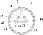
FIG. 2 is a front cross-sectional view of a monorail crane transport apparatus in accordance with the present invention;
FIG. 3 is a side cross-sectional view of the right mounting plate of the monorail crane transport apparatus of the present invention;
FIG. 4 is a side cross-sectional view of the left mounting plate of the monorail car conveyor system of the present invention.
In the figure: 1. a roadway; 2. a T-shaped track; 3. a boom; 4. a left mounting plate; 5. a right mounting plate; 6. a drive motor; 7. a vertical plate; 8. rotating the rod; 9. a drive wheel; 10. a draw bar; 11. a crane; 12. a wire rope; 13. a drive shaft; 14. hooking; 15. a servo motor; 16. a support plate; 17. a groove; 18. a moving wheel; 19. a drive chain; 20. a driven sprocket; 21. a drive sprocket; 22. a bidirectional screw rod; 23. a slide plate; 24. a chain; 25. driving the sprocket.
Detailed Description
The technical solutions in the embodiments of the present invention will be clearly and completely described below with reference to the drawings in the embodiments of the present invention, and it is obvious that the described embodiments are only a part of the embodiments of the present invention, and not all of the embodiments.
Referring to fig. 1-4, the monorail crane transportation device comprises a roadway 1, a left mounting plate 4 and a right mounting plate 5, wherein a T-shaped track 2 is fixedly arranged on the inner wall of the top of the roadway 1, two vertical plates 7 are fixedly arranged on the top of the right mounting plate 5, two rotary rods 8 are rotatably arranged on the mutually adjacent sides of the two vertical plates 7, driving wheels 9 are fixedly arranged at the inner ends of the four rotary rods 8, the four driving wheels 9 are all connected to the T-shaped track 2 in a rolling manner, driven sprockets 20 are fixedly sleeved on the outer sides of the four rotary rods 8, a driving motor 6 is fixedly arranged on the front side of the vertical plate 7 on the front side, a driving shaft 13 is fixedly arranged on an output shaft of the driving motor 6, two driving sprockets 21 are fixedly sleeved on the outer side of the driving shaft 13, the same transmission chain 19 is in transmission connection with the driving sprocket 21 and the two driven sprockets 20 on the front side and the driving sprocket 21 and the two driven sprockets 20 on the rear side, the same draw bar 10 is rotatably arranged between the left mounting plate 4 and the right mounting plate 5, two cranes 11 are fixedly arranged at the top of the left mounting plate 4, a steel wire rope 12 is arranged at the bottom of each crane 11, a hook 14 is fixedly arranged at the bottom end of each steel wire rope 12, an object to be transported can be lifted through the cooperation of the cranes 11, the steel wire ropes 12 and the hooks 14, then the crane is rotatably connected with the right mounting plate 5 through the draw bar 10, a driving motor 6 is started, the driving motor 6 drives a driving shaft 13 and two driving sprockets 21 to rotate, four driven sprockets 20, a rotating rod 8 and a driving wheel 9 are driven to synchronously rotate through the transmission of a transmission chain 19, so that the left mounting plate 4 and the object to be transported can be driven to move, the object can be conveniently lifted and transported, two grooves 17 are formed at the top of the left mounting plate 4, and the same two-way screw rods 22 are rotatably arranged on the inner walls on the front side and the back side of the grooves 17, the rear ends of the two bidirectional screw rods 22 are fixedly provided with driving chain wheels 25, the two driving chain wheels 25 are in transmission connection with the same chain 24, the front side of the left mounting plate 4 is fixedly provided with a servo motor 15, the output shaft of the servo motor 15 is fixedly arranged at the front end of the corresponding bidirectional screw rod 22, the outer side of the bidirectional screw rod 22 is sleeved with two supporting plates 16 in a sliding manner, the inner sides of the four supporting plates 16 are respectively and rotatably provided with moving wheels 18, the four moving wheels 18 are all connected to the T-shaped track 2 in a rolling manner, the servo motor 15 is started according to the width of the T-shaped track 2, the servo motor 15 drives the rotation of one bidirectional screw rod 22, under the transmission of the driving chain wheels 25 and the chain 24, the two bidirectional screw rods 22 synchronously rotate, the two bidirectional screw rods 22 drive the four supporting plates 16 to be close to the inner side or far away from the outer side, and the four supporting plates 16 drive the four moving wheels 18 to be close to or far away from each other, thereby the interval between four adjustable removal wheels 18, the left mounting panel 4 of being convenient for is connected on the T type track 2 of different width, and then has made things convenient for the use, when needs overhaul the hoist 11 when maintaining simultaneously, also can start servo motor 15 for four remove wheel 18 and outwards keep away from, and then break away from T type track 2, thereby can dismantle left mounting panel 4 down, overhaul the maintenance to hoist 11.
In the utility model, the inner wall of the bottom of the groove 17 is provided with sliding grooves, four sliding plates 23 are slidably sleeved in the two sliding grooves, the four sliding plates 23 are respectively and fixedly arranged at the bottom of the corresponding supporting plate 16, and the supporting plate 16 is guided and limited by the sliding plates 23 and does not rotate together with the bidirectional screw rod 22.
In the utility model, rotating shafts are rotatably arranged on the inner sides of the four supporting plates 16, the four moving wheels 18 are respectively fixedly sleeved on the outer sides of the corresponding rotating shafts, and the four moving wheels 18 are respectively rotatably arranged on the inner sides of the corresponding supporting plates 16 through the rotating shafts.
According to the utility model, two suspenders 3 are fixedly installed at the top of the T-shaped rail 2, the two suspenders 3 are both fixedly arranged on the inner wall of the top of the roadway 1, and the T-shaped rail 2 is conveniently and fixedly installed on the inner wall of the top of the roadway 1 through the suspenders 3.
According to the utility model, two limiting holes are formed in the top of the left mounting plate 4, the two steel wire ropes 12 are movably sleeved in the corresponding limiting holes, the steel wire ropes 12 are guided and limited through the limiting holes, and the steel wire ropes 12 are effectively prevented from shaking greatly during hoisting.
In the utility model, one end of the traction rod 10 is rotatably arranged at one side of the left mounting plate 4 through a hinge, the other end of the traction rod 10 is rotatably arranged at one side of the right mounting plate 5 through a hinge, and the traction rod 10 is conveniently rotatably arranged between the left mounting plate 4 and the right mounting plate 5 through the hinge.
In the utility model, when in use, according to the width of the T-shaped track 2, the servo motor 15 is started, the servo motor 15 drives the rotation of one two-way screw rod 22, the two-way screw rods 22 synchronously rotate under the transmission of the driving chain wheel 25 and the chain 24, the two-way screw rods 22 drive the four support plates 16 to be close to the inner side or to be far away from the outer side under the limit of the sliding plate 23, the four support plates 16 drive the four moving wheels 18 to be close to or away from each other, so that the space among the four moving wheels 18 can be adjusted, the left mounting plate 4 can be conveniently connected on the T-shaped tracks 2 with different widths, the use is further convenient, meanwhile, when the crane 11 needs to be overhauled and maintained, the servo motor 15 can be started, so that the four moving wheels 18 are far away from the outer side to be separated from the T-shaped track 2, so that the lower left mounting plate 4 can be disassembled to overhaul and maintain the crane 11, through the cooperation of hoist 11, wire rope 12 and couple 14, can lift the object of waiting to transport, then rotate with right mounting panel 5 through traction lever 10 and be connected, start driving motor 6, driving motor 6 has driven the rotation of drive shaft 13 and two driving sprocket 21, through the transmission of driving chain 19, has driven the synchronous rotation of four driven sprocket 20, rotary rod 8 and drive wheel 9 to can drive the removal of left mounting panel 4 and the object of waiting to transport, thereby convenient the transportation of lifting by crane of object.
Claims (6)
1. The monorail hoisting device comprises a roadway (1), a left mounting plate (4) and a right mounting plate (5), and is characterized in that a T-shaped track (2) is fixedly arranged on the inner wall of the top of the roadway (1), two vertical plates (7) are fixedly arranged on the top of the right mounting plate (5), two rotary rods (8) are rotatably arranged on one sides of the two vertical plates (7) close to each other, driving wheels (9) are fixedly arranged at the inner ends of the four rotary rods (8), the four driving wheels (9) are connected to the T-shaped track (2) in a rolling manner, driven sprockets (20) are fixedly sleeved on the outer sides of the four rotary rods (8), a driving motor (6) is fixedly arranged on the front side of the vertical plate (7) positioned on the front side, a driving shaft (13) is fixedly arranged on an output shaft of the driving motor (6), and two driving sprockets (21) are fixedly sleeved on the outer side of the driving shaft (13), the chain transmission mechanism is characterized in that the same transmission chain (19) is in transmission connection with a driving chain wheel (21) and two driven chain wheels (20) on the front side and the same transmission chain (19) is in transmission connection with a driving chain wheel (21) and two driven chain wheels (20) on the rear side, the same traction rod (10) is rotatably arranged between a left mounting plate (4) and a right mounting plate (5), two cranes (11) are fixedly arranged at the top of the left mounting plate (4), steel wire ropes (12) are arranged at the bottoms of the cranes (11), hooks (14) are fixedly arranged at the bottom ends of the steel wire ropes (12), two grooves (17) are formed at the top of the left mounting plate (4), the same two-way screw rods (22) are rotatably arranged on the inner walls of the front side and the rear side of each groove (17), driving chain wheels (25) are fixedly arranged at the rear ends of the two-way screw rods (22), and the same chain (24) is in transmission connection with the two driving chain wheels (25), the fixed servo motor (15) that is provided with of front side of left side mounting panel (4), the fixed two-way lead screw (22) front end that sets up in the correspondence of output shaft of servo motor (15), two backup pads (16) have been cup jointed in the outside slip of two-way lead screw (22), and the inboard of four backup pads (16) all rotates and is provided with and removes wheel (18), and four remove the equal roll connection of wheel (18) on T type track (2).
2. The monorail crane transportation device as defined in claim 1, wherein the bottom inner wall of the groove (17) is provided with sliding grooves, four sliding plates (23) are slidably sleeved in each of the two sliding grooves, and the four sliding plates (23) are respectively and fixedly arranged at the bottom of the corresponding support plate (16).
3. The monorail crane transportation device of claim 1, wherein the inner sides of the four supporting plates (16) are rotatably provided with rotating shafts, and the four moving wheels (18) are fixedly sleeved on the outer sides of the corresponding rotating shafts respectively.
4. The monorail crane transportation device of claim 1, wherein two suspension rods (3) are fixedly mounted on the top of the T-shaped rail (2), and both suspension rods (3) are fixedly arranged on the inner wall of the top of the roadway (1).
5. The monorail crane transportation device as defined in claim 1, wherein two limiting holes are formed at the top of the left mounting plate (4), and the two steel wire ropes (12) are movably sleeved in the corresponding limiting holes.
6. The monorail crane transportation device of claim 1, wherein one end of the traction rod (10) is rotatably arranged on one side of the left mounting plate (4) through a hinge, and the other end of the traction rod (10) is rotatably arranged on one side of the right mounting plate (5) through a hinge.
Priority Applications (1)
| Application Number | Priority Date | Filing Date | Title |
|---|---|---|---|
| CN202122707306.9U CN216188638U (en) | 2021-11-05 | 2021-11-05 | Monorail crane transportation device |
Applications Claiming Priority (1)
| Application Number | Priority Date | Filing Date | Title |
|---|---|---|---|
| CN202122707306.9U CN216188638U (en) | 2021-11-05 | 2021-11-05 | Monorail crane transportation device |
Publications (1)
| Publication Number | Publication Date |
|---|---|
| CN216188638U true CN216188638U (en) | 2022-04-05 |
Family
ID=80904329
Family Applications (1)
| Application Number | Title | Priority Date | Filing Date |
|---|---|---|---|
| CN202122707306.9U Active CN216188638U (en) | 2021-11-05 | 2021-11-05 | Monorail crane transportation device |
Country Status (1)
| Country | Link |
|---|---|
| CN (1) | CN216188638U (en) |
-
2021
- 2021-11-05 CN CN202122707306.9U patent/CN216188638U/en active Active
Similar Documents
| Publication | Publication Date | Title |
|---|---|---|
| CN107420119B (en) | Quick uninstallation device of shield constructs quick-witted section of jurisdiction | |
| CN211310671U (en) | Lifting device for building engineering | |
| CN108750668A (en) | A kind of door of elevator production line feeding and conveying device | |
| CN213976674U (en) | Lifting beam for monorail crane | |
| CN216188638U (en) | Monorail crane transportation device | |
| CN212151384U (en) | Lifting equipment suitable for foundation pit operation | |
| CN219384523U (en) | Cross lifting beam for bilateral lifting of motor | |
| CN208544840U (en) | A kind of door of elevator production line feeding and conveying device | |
| CN116495501A (en) | Train container unloading system and unloading method | |
| CN216687187U (en) | A dismantlement formula gallows equipment for coal mine equipment fixing | |
| CN215798047U (en) | Special crane for grinding roller | |
| CN216613825U (en) | Rolling mill presses pneumatic cylinder on and changes device | |
| CN214616589U (en) | Tunnel bow member erection equipment | |
| CN210176324U (en) | Trolley hoisting device | |
| CN211004232U (en) | Hanging beam crane with floor function | |
| CN106629375A (en) | Lifting mechanism for single-rail crane and single-rail crane lifting beam | |
| CN209081287U (en) | A kind of dedicated bridge crane of brick equipment | |
| CN108265630B (en) | Material conveying and hanging basket system for bridge construction | |
| CN206307610U (en) | A kind of chain scraper elevator | |
| CN211198379U (en) | Simple and easy track hoist device | |
| CN108975172A (en) | A kind of dedicated bridge crane of brick equipment | |
| CN221093521U (en) | Novel lifting operation mechanism | |
| CN213923740U (en) | Combined glass curtain wall hoisting construction equipment | |
| CN213415271U (en) | Power and free type suspension conveying equipment | |
| CN219259388U (en) | Portal frame is transported to ecological stone |
Legal Events
| Date | Code | Title | Description |
|---|---|---|---|
| GR01 | Patent grant | ||
| GR01 | Patent grant |