CN216104790U - Full-automatic stamping and collecting equipment - Google Patents
Full-automatic stamping and collecting equipment Download PDFInfo
- Publication number
- CN216104790U CN216104790U CN202122594648.4U CN202122594648U CN216104790U CN 216104790 U CN216104790 U CN 216104790U CN 202122594648 U CN202122594648 U CN 202122594648U CN 216104790 U CN216104790 U CN 216104790U
- Authority
- CN
- China
- Prior art keywords
- assembly
- loading
- butt joint
- conveyor belt
- module
- Prior art date
- Legal status (The legal status is an assumption and is not a legal conclusion. Google has not performed a legal analysis and makes no representation as to the accuracy of the status listed.)
- Active
Links
Images


Landscapes
- Specific Conveyance Elements (AREA)
Abstract
The utility model aims to provide the full-automatic stamping and receiving equipment which is strong in compatibility, can adapt to high-speed stamping production equipment and prevents products from being damaged. The material collecting device comprises a butt joint conveying belt assembly and a plurality of groups of material collecting modules which are sequentially connected, wherein the input end of the butt joint conveying belt assembly is connected with the output end of stamping equipment, each material collecting module comprises a carrying module, a conveying belt assembly, a material basket and a loading and transporting module, the output end of the butt joint conveying belt assembly is connected with the conveying belt assembly of the first group of material collecting modules through a guide frame assembly, the conveying belt assemblies of the two adjacent groups of material collecting modules are in butt joint, the material basket is loaded on the loading and transporting module, a plurality of product limiting grooves are formed in the material basket, materials on the conveying belt assemblies are sucked by the carrying modules and then moved to the loading and transporting module, and products are loaded in the product limiting grooves by the loading and transporting module. The utility model is applied to the technical field of charging equipment.
Description
Technical Field
The utility model is applied to the technical field of charging equipment, and particularly relates to full-automatic stamping and material receiving equipment.
Background
The efficiency of the existing stamping equipment is high, and rapid material stamping can be continuously carried out, wherein the middle frame structure of an electronic product, particularly the middle frame structure of a mobile phone is used for connecting a screen or a circuit board structure, the area is small, the hollow part is more, the structural rigidity is low, and if the middle frame structure is stressed unevenly or receives large impact force in the loading process, bending can be easily carried out. In addition, because the area of the middle frame structure of the mobile phone is small, the stamping equipment can stamp more products at one time, and the requirement on the material receiving efficiency of the material receiving equipment is high. Receive material equipment and adopt the conveyer belt subassembly to carry out the conveying of material usually, so need absorb the product earlier from the conveyer belt subassembly through inhaling the material subassembly when feeding, inhale the material in order to guarantee to inhale the accuracy of material structure, the conventional material flow of inhaling is provided with the sensor that targets in place on the conveyer belt subassembly, conveyer belt subassembly stop operation after the material reaches gets the material position, get the material by inhaling the material subassembly again, so accomplish whole material flow of getting and carry out the sabot again after. However, stopping the conveyor belt assembly may have an efficiency that does not match the stamping apparatus, so that the stamping apparatus may also need to be stopped for waiting.
The existing chinese patent with publication number CN104139982B discloses a punching material-receiving tray-placing machine, which includes a material-receiving conveying mechanism for realizing automatic spacing and conveying of materials, a suction-turning mechanism for sucking the materials conveyed by the material-receiving conveying mechanism and turning the materials, and a material-guiding mechanism for guiding the materials turned by the suction-turning mechanism into a material tray. Although the material can be continuously sucked and palletized when the technical scheme works and the conveying structure is not needed to be stopped, the material sucking accuracy can be ensured only by positioning the material by using the spacing structure, and meanwhile, the material sucking device cannot be compatible with products of different sizes.
SUMMERY OF THE UTILITY MODEL
The utility model aims to overcome the defects of the prior art and provides the full-automatic stamping and receiving equipment which is strong in compatibility, can adapt to high-speed stamping production equipment and prevents products from being damaged.
The technical scheme adopted by the utility model is as follows: the material collecting device comprises a butt joint conveying belt assembly and a plurality of groups of material collecting modules which are sequentially connected, wherein the input end of the butt joint conveying belt assembly is connected with the output end of stamping equipment, each material collecting module comprises a carrying module, a conveying belt assembly, a material basket and a loading and transporting module, the output end of the butt joint conveying belt assembly is connected with the conveying belt assembly of the first group of material collecting modules through a guide frame assembly, the conveying belt assemblies of the two adjacent groups of material collecting modules are in butt joint, the material basket is loaded on the loading and transporting module, a plurality of product limiting grooves are formed in the material basket, materials on the conveying belt assemblies are sucked by the carrying modules and then moved to the loading and transporting module, and products are loaded in the product limiting grooves by the loading and transporting module.
According to the scheme, the abutting joint conveyor belt assembly is matched with the output end of the stamping device to receive and take the stamped product, and the product can smoothly slide onto the conveyor belt assembly by arranging the guide frame assembly. The receiving module is sequentially connected by adopting a plurality of groups, and the conveying belt assemblies of the receiving module are butted to form a complete conveying belt with long conveying distance. And then the carrying modules in each group of material receiving modules are used for taking the products, the material taking of the material receiving modules in each group is not interfered with each other, and the subsequent material receiving modules can take the products which are not taken by the previous group of material receiving modules away, so that the material receiving efficiency is complemented, and the stamping equipment can be well adapted to the high efficiency. The material basket is an appliance finally used for loading products, and the products are limited and supported by arranging a plurality of product limiting grooves. The loading and transporting module and the carrying module are matched to carry conveyed products, the products are stably placed in the material basket, and meanwhile, the loading and transporting module is used for bearing the moving and positioning of the material basket.
According to a preferred scheme, the carrying module comprises a first linear moving mechanism, a fixing frame and a plurality of groups of material sucking assemblies, wherein the first linear moving mechanism is arranged above the conveyor belt assembly, the fixing frame is fixed to the movable end of the first linear moving mechanism, the material sucking assemblies are arranged on the fixing frame in an array mode, each material sucking assembly comprises a lifting cylinder and a connecting plate, the connecting plate is fixed to the movable end of the lifting cylinder, a vacuum air path is arranged in the connecting plate, a vacuum sucker communicated with the vacuum air path is arranged on the connecting plate, and the vacuum air path is communicated with a vacuum generator.
It is seen by above-mentioned scheme that through the multiunit that sets up side by side inhale the material subassembly and realize the absorption to the material, the while single transportation absorbs polylith product in turn, and then raises the efficiency, when a set of when the handling subassembly transports that feeds, then by next a set of the material module is got to the handling subassembly of receiving the material module. The first linear moving mechanism drives the fixing frame to move so as to drive the suction assembly and the conveying belt assembly to be matched. Buffering is performed through a vacuum chuck, and meanwhile negative pressure is provided to achieve suction of products from the conveyor belt assembly.
Further preferred scheme is, inhale material subassembly still includes at least a set of photoelectric sensor, photoelectric sensor sets up the connecting plate is kept away from the one end of butt joint conveyer belt subassembly, photoelectric sensor with the product cooperation on the conveyer belt subassembly.
According to the scheme, the photoelectric sensor is arranged to detect materials on the conveyor belt assembly, after the products are triggered, the lifting cylinder stretches out while the vacuum chuck generates negative pressure, and then the products are adsorbed on the vacuum chuck. Real-time response is realized through this structure and is absorb, absorb stably and need not the conveyer belt subassembly and shut down, guarantee the conveying efficiency of conveyer belt subassembly can match stamping equipment's production efficiency.
Further preferred scheme is, conveyor assembly keeps away from one side of the transportation module of feeding is provided with the recovery tray, the one end of recovery tray be connected with inhale material subassembly complex direction slide.
According to the scheme, the recovery tray is arranged to recover defective products such as stamping damage or deviation, and the visual detection is carried out by the material receiving module or the visual module on the front equipment. The carrying module is used for sorting products according to the identification data of the vision module, and the defective products are moved to the upper portion of the guide slide way after being sucked to be thrown.
One preferred scheme is that the material receiving module further comprises an installation rack, the material loading and transporting module comprises a second linear moving mechanism, a carrier assembly, a butt joint guide rail and a carrying and loading assembly, the second linear moving mechanism and the butt joint guide rail are fixed on the installation rack, the carrier assembly is in sliding fit on the installation rack, the carrier assembly is connected with the movable end of the second linear moving mechanism, the carrier assembly is in matched butt joint with the butt joint guide rail, the material basket is loaded on the carrier assembly, the carrying and loading assembly comprises a third linear moving mechanism and a lifting plate, the third linear moving mechanism is arranged along the vertical direction, the lifting plate is fixed on the movable end of the third linear moving mechanism, and a rotary driving assembly is arranged on the lifting plate, an output shaft of the rotary driving assembly is connected with a rotating shaft which is in running fit with the lifting plate, and a plurality of vacuum suction plates which are correspondingly matched with the suction assemblies are arranged on the rotating shaft in an array mode.
According to the scheme, the second linear moving mechanism is used for driving the carrier assembly to be close to or far away from the receiving and loading assembly, so that the material basket on the carrier assembly is moved, and the receiving and loading assembly places products in different product limiting grooves on the material basket. The butt joint guide rail is used for being matched with an external transportation mechanism to realize connection of the carrier assembly and the external transportation mechanism, so that the material basket is driven by the carrier assembly to be conveyed into the transportation mechanism. The lifting plate is driven to move up and down through the third linear moving mechanism, and then the material sucking assembly and the receiving and loading assembly are matched to transfer products. The rotary driving assembly drives the lifting plate to rotate through the rotating shaft, so that the posture of a product is changed, and the material basket is adaptive in structure to prevent abrasion caused by mutual collision among the products.
A further preferred scheme is, the carrier subassembly includes activity support plate and driving motor, activity support plate sliding fit is in the installation frame, the activity support plate with the expansion end of second rectilinear movement mechanism is connected, the both sides of activity support plate all rotate be provided with a plurality of with basket bottom complex conveying roller, rotate on the activity support plate be provided with the transmission shaft that driving motor transmission is connected, the transmission shaft passes through chain drive structure and drives a plurality of conveying roller rotates in step.
According to the scheme, the driving motor drives all the conveying rollers to rotate, and then the conveying rollers are matched with the bottom of the material basket to drive the material basket to move, so that the material basket is loaded and unloaded. When the movable carrier plate is in butt joint with the butt joint guide rail, the material basket is aligned with the butt joint guide rail and can slide to the butt joint guide rail.
A further preferred scheme is that at least two sets of side top cylinders are arranged on one side of the movable carrier plate, which is far away from the bearing and loading assembly, a limiting block matched with the material basket is arranged on the other side of the movable carrier plate, and a detection sensor matched with the material basket is further arranged on one side of the movable carrier plate, which is provided with the limiting block.
According to the scheme, the side top air cylinder is matched with the limiting block to limit the material basket in the tray loading process, and the detection sensor is arranged to detect the in-place condition of the material basket.
A further preferred scheme is that the bearing and loading assembly further comprises a buffer bearing assembly, the buffer bearing assembly comprises a movable air cylinder and a connecting piece, the movable air cylinder and the connecting piece are arranged inside the installation frame, the connecting piece is fixed to the movable end of the movable air cylinder, a through hole matched with the connecting piece is formed in the installation frame, a plurality of bearing blocks matched with the vacuum suction plates are correspondingly arranged on the connecting piece, and buffer limiting grooves are formed in the bearing blocks.
According to the scheme, the buffer bearing assembly is matched with the vacuum suction plates to take the products. The diameter of the bearing block is smaller than the passing clearance of the product limiting groove, the bearing block penetrates from the bottom of the material basket and receives the product in one step, the buffering limiting groove is used for being in contact with the bottom of the product to support and limit the lower part of the product, and the bearing block slowly descends through the movable air cylinder after receiving, so that the product is stably prevented from being damaged in the product limiting groove. The lifting speed of the movable air cylinder can be adjusted according to the requirement.
The lifting plate is provided with two groups of buffers which are respectively matched with the two limit stops.
According to the scheme, the two limit stops on the limit disc are respectively matched with the buffer, so that the rotation angle of the rotation shaft is limited, and the product posture is matched with the product limit groove.
One preferred scheme is, the leading truck subassembly includes guide way board and two at least pairs of connecting rods, the one end of connecting rod with guide way board fixed connection, the other end of connecting rod is provided with waist type hole, the connecting rod pass through waist type hole with butt joint conveyer belt assembly's frame is connected fixedly.
According to the scheme, the waist-shaped holes are formed in the connecting rods, so that the mounting height of the connecting rods can be adjusted adaptively, the inclination of the guide groove plates can be adjusted by changing the relative positions of the two pairs of connecting rods, and the acceleration required by the downward sliding of products with different sizes is provided.
Drawings
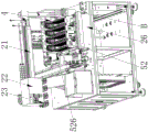
FIG. 1 is a schematic perspective view of the present invention;
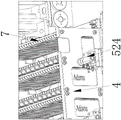
FIG. 2 is a schematic view of the docking structure of the docking conveyor assembly and the material receiving module;
FIG. 3 is an enlarged view of portion A of FIG. 2;
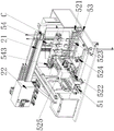
FIG. 4 is a schematic perspective view of the material receiving module;
FIG. 5 is an enlarged view of portion B of FIG. 4;
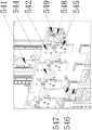
FIG. 6 is a schematic view of a part of the receiving module;
FIG. 7 is an enlarged view of portion C of FIG. 6;
fig. 8 is a schematic perspective view of the suction assembly 23 according to the second embodiment.
Detailed Description
The first embodiment is as follows:
as shown in fig. 1 to 7, in the present embodiment, the utility model includes an abutting-joint conveyor belt assembly 1 and several groups of material receiving modules connected in sequence, the input end of the butt joint conveyor belt component 1 is connected with the output end of the stamping equipment, the material receiving module comprises a carrying module 2, a conveyor belt component 3, a material basket 4 and a loading and transporting module 5, the output end of the butt joint conveyor belt component 1 is connected with the conveyor belt component 3 of the first group of material receiving modules through a guide frame component 6, the conveyor belt components 3 of the two adjacent groups of material receiving modules are in butt joint, the material basket 4 is loaded on the loading and transporting module 5, a plurality of product limiting grooves 7 are arranged on the material basket 4, the material on the conveying belt component 3 is sucked and then moved to the loading and transporting module 5 by the carrying module 2, and the product is loaded in the product limiting groove 7 by the loading and transporting module 5.
In this embodiment, the carrying module 2 includes a first linear moving mechanism 21, a fixing frame 22 and four groups of material sucking assemblies 23, the first linear moving mechanism 21 is disposed above the conveying belt assembly 3, the fixing frame 22 is fixed on the movable end of the first linear moving mechanism 21, the four groups of material sucking assemblies 23 are arranged on the fixing frame 22 in an array manner, each material sucking assembly 23 includes a lifting cylinder 231 and a connecting plate 232, the connecting plate 232 is fixed on the movable end of the lifting cylinder 231, a vacuum air path is disposed in the connecting plate 232, a vacuum sucker communicated with the vacuum air path is disposed on the connecting plate 232, and the vacuum air path is communicated with a vacuum generator.
In this embodiment, the suction assembly 23 further includes a set of photoelectric sensors 233, the photoelectric sensors 233 are disposed at an end of the connecting plate 232 away from the butt-joint conveyor belt assembly 1, and the photoelectric sensors 233 are matched with the products on the conveyor belt assembly 3.
In this embodiment, one side of the conveying belt assembly 3, which is far away from the loading and transporting module 5, is provided with a recovery tray 24, and one end of the recovery tray 24 is connected with a guide slideway 25 matched with the material suction assembly 23.
In this embodiment, the material collecting module further includes an installation frame 26, the loading and transporting module 5 includes a second linear moving mechanism 51, a carrier assembly 52, a docking guide 53 and a receiving and loading assembly 54, the second linear moving mechanism 51 and the docking guide 53 are both fixed on the installation frame 26, the carrier assembly 52 is slidably fitted on the installation frame 26, the carrier assembly 52 is connected to the movable end of the second linear moving mechanism 51, the carrier assembly 52 is fittingly docked with the docking guide 53, the basket 4 is loaded on the carrier assembly 52, the receiving and loading assembly 54 includes a third linear moving mechanism 541 and a lifting plate 542 which are arranged above the carrier assembly 52, the third linear moving mechanism 541 is arranged along the vertical direction, and the lifting plate 542 is fixed on the movable end of the third linear moving mechanism 541, the lifting plate 542 is provided with a rotary driving assembly 543, an output shaft of the rotary driving assembly 543 is connected with a rotating shaft 544 which is rotatably matched with the lifting plate 542, and four groups of vacuum suction plates 545 which are correspondingly matched with the four groups of suction assemblies 23 are arranged on the rotating shaft 544 in an array manner. The first linear movement mechanism 21 and the second linear movement mechanism 51 are both linear electric cylinders. Third rectilinear movement mechanism 541 includes motor, lead screw and lead screw slider, the motor is fixed in second rectilinear movement mechanism 51's the frame, lead screw slider adaptation is in on the lead screw, lifter plate 542 sliding fit is in second rectilinear movement mechanism 51's the frame, just lifter plate 542 with lead screw slider fixed connection, the output shaft of motor passes through the hold-in range drive the lead screw rotates, and then drives lifter plate 542 goes up and down, through adopting the lead screw that has accurate transmission as drive mechanism and then realize the accurate lift of lifter plate 542.
In this embodiment, the carrier assembly 52 includes a movable carrier plate 521 and a driving motor 522, the movable carrier plate 521 is slidably fitted on the mounting frame 26, the movable carrier plate 521 is connected to the movable end of the second linear moving mechanism 51, a plurality of conveying rollers 523 engaged with the bottom of the basket 4 are rotatably disposed on both sides of the movable carrier plate 521, a transmission shaft in transmission connection with the driving motor 522 is rotatably disposed on the movable carrier plate 521, and the transmission shaft drives the plurality of conveying rollers 523 to rotate synchronously through a chain transmission structure.
In this embodiment, at least two sets of side top cylinders 524 are disposed on a side of the movable carrier plate 521 away from the receiving and loading assembly 54, a limit block 525 engaged with the material basket 4 is disposed on the other side of the movable carrier plate 521, and a detection sensor 526 engaged with the material basket 4 is further disposed on a side of the movable carrier plate 521 where the limit block 525 is disposed.
In this embodiment, the receiving and loading assembly 54 further includes a buffering and bearing assembly, the buffering and bearing assembly includes a movable cylinder and a connecting member disposed inside the mounting frame 26, the connecting member is fixed on a movable end of the movable cylinder, a through hole adapted to the connecting member is disposed on the mounting frame 26, the through hole is located right below the lifting plate 542, four sets of bearing blocks 546 matched with the four sets of vacuum suction plates 545 are correspondingly disposed on the connecting member, and a buffering limit groove 547 is disposed on each bearing block 546.
In this embodiment, a limiting disc 548 is disposed at an end of the rotating shaft 544, two limiting stoppers are disposed on the limiting disc 548, and two sets of buffers 549 respectively engaged with the two limiting stoppers are disposed on the lifting plate 542.
In this embodiment, the guide frame assembly 6 includes a guide slot plate 61 and at least two pairs of connecting rods 62, one end of each connecting rod 62 is fixedly connected to the guide slot plate 61, the other end of each connecting rod 62 is provided with a waist-shaped hole 63, and the connecting rods 62 are fixedly connected to the frame of the butt joint conveyor belt assembly 1 through the waist-shaped holes 63.
The working principle of the utility model is as follows:
firstly, the butt joint conveyor belt assembly 1 receives products coming out of a stamping device and conveys the products to the conveyor belt assembly 3 of the first group of material receiving modules, and the conveyor belt assembly 3 continuously drives the products to do linear motion. The first linear moving mechanism 21 drives the fixing frame 22 to move to the position above the conveying belt assembly 3, the material sucking assembly 23 which does not suck the product is aligned with the conveying belt assembly 3, when the photoelectric sensor 233 detects that the product passes through the conveying belt assembly 3, a feedback signal is sent back, the lifting cylinder 231 drives the connecting plate 232 to descend, the product is sucked and lifted through the vacuum chuck, and after one material taking is completed, the first linear moving mechanism 21 drives the fixing frame 22 to move and switch another group of material sucking assemblies 23 which do not take the material to take the material. After the four groups of material suction assemblies 23 suck materials, the first linear moving mechanism 21 drives the fixed frame 22 to move to the position above the loading and transporting module 5 to perform product loading operation. When the material loading operation of the product is carried out, the material taking operation is replaced by the next group of material receiving modules, and then the continuous material receiving and tray loading are realized. In addition, the shape of the product is judged by the vision module, when the defective product is absorbed by the carrying module 2, the material throwing operation is executed, the defective product is thrown on the guide slide way 25, and the defective product falls into the recovery tray 24.
When the product loading operation is performed, the two groups of side top air cylinders 524 extend out to clamp the material basket 4 on the movable carrier plate 521, the rotary driving assembly 543 rotates the four groups of vacuum suction plates 545 to a horizontal state, the material suction assembly 23 breaks vacuum to place a product on the vacuum suction plates 545, and a suction cup structure on the vacuum suction plates 545 is connected with a vacuum generator to generate negative pressure to suck the product tightly. The rotary driving assembly 543 drives the four sets of vacuum suction plates 545 to rotate to a vertical state through the rotating shaft 544, and matches with the product limiting grooves 7 on the material basket 4. The bearing block 546 is lifted to the material receiving height, the third linear moving mechanism 541 drives the lifting plate 542 to descend and stably place products in the buffer limiting groove 547 of the bearing block 546, after the bearing block 546 receives the products, the movable cylinder retracts to drive the connecting block to descend, so that the bearing block 546 places the products in the product limiting groove 7, and the products are prevented from being damaged.
After a group of products is placed, the second linear moving mechanism 51 drives the carrier component 52 to move by the distance of one product limiting groove 7, and then switches another group of product limiting grooves 7 to receive and take the products.
After loading all the products in the product limiting grooves 7 on the material basket 4, the second linear moving mechanism 51 drives the movable carrier plate 521 to be in butt joint with the butt joint guide rail 53, and the driving motor 522 drives the plurality of conveying rollers 523 to drive the material basket 4 to slide to the external transportation mechanism through the butt joint guide rail 53.
Example two:
as shown in fig. 8, the present embodiment is different from the first embodiment in that: the material suction assembly 23 comprises two groups of photoelectric sensors 233, the two groups of photoelectric sensors 233 are respectively arranged at two ends of the connecting plate 232, and the two groups of photoelectric sensors 233 are matched with products on the conveying belt assembly 3.
By arranging two sets of the photoelectric sensors 233 at the same time, when the photoelectric sensor 233 close to one end of the butt joint conveyor belt assembly 1 recognizes a product, the lifting cylinder 231 enters preparation to slowly extend, and the lifting cylinder 231 is driven to rapidly respond and extend after the photoelectric sensor 233 of the other set recognizes the product, so that accurate product suction is realized.
Claims (10)
1. Full-automatic punching press is received material equipment, its characterized in that: the automatic material receiving device comprises a butt joint conveyor belt assembly (1) and a plurality of groups of material receiving modules which are connected in sequence, wherein the input end of the butt joint conveyor belt assembly (1) is connected with the output end of a stamping device, each material receiving module comprises a conveying module (2), a conveyor belt assembly (3), a material basket (4) and a material loading and transporting module (5), the output end of the butt joint conveyor belt assembly (1) is connected with the conveyor belt assembly (3) of the material receiving module through a guide frame assembly (6), the conveyor belt assemblies (3) of the two adjacent groups of material receiving modules are in butt joint, the material basket (4) is loaded on the material loading and transporting module (5), a plurality of product limiting grooves (7) are formed in the material basket (4), and the conveying module (2) absorbs materials on the conveyor belt assembly (3) and then moves to the material loading and transporting module (5), the loading and transporting module (5) loads the products in the product limiting groove (7).
2. The full-automatic punching and collecting device of claim 1, characterized in that: the conveying module (2) comprises a first linear moving mechanism (21), a fixing frame (22) and a plurality of groups of suction assemblies (23), wherein the first linear moving mechanism (21) is arranged above the conveyor belt assembly (3), the fixing frame (22) is fixed on the movable end of the first linear moving mechanism (21), the suction assemblies (23) are arranged on the fixing frame (22) in an array mode, each suction assembly (23) comprises a lifting cylinder (231) and a connecting plate (232), the connecting plates (232) are fixed on the movable end of the lifting cylinder (231), vacuum air channels are formed in the connecting plates (232), vacuum suction cups communicated with the vacuum air channels are arranged on the connecting plates (232), and the vacuum air channels are communicated with a vacuum generator.
3. The full-automatic punching and collecting device of claim 2, characterized in that: the material suction assembly (23) further comprises at least one group of photoelectric sensors (233), the photoelectric sensors (233) are arranged at one end, far away from the butt joint conveyor belt assembly (1), of the connecting plate (232), and the photoelectric sensors (233) are matched with products on the conveyor belt assembly (3).
4. The full-automatic punching and collecting device of claim 2, characterized in that: one side of the conveyor belt assembly (3) far away from the loading and transporting module (5) is provided with a recovery tray (24), and one end of the recovery tray (24) is connected with a guide slide way (25) matched with the suction assembly (23).
5. The full-automatic punching and collecting device of claim 2, characterized in that: the material receiving module further comprises an installation rack (26), the loading and transporting module (5) comprises a second linear moving mechanism (51), a carrier assembly (52), a butt joint guide rail (53) and a receiving and loading assembly (54), the second linear moving mechanism (51) and the butt joint guide rail (53) are fixed on the installation rack (26), the carrier assembly (52) is in sliding fit on the installation rack (26), the carrier assembly (52) is connected with the movable end of the second linear moving mechanism (51), the carrier assembly (52) is in matched butt joint with the butt joint guide rail (53), the material basket (4) is loaded on the carrier assembly (52), the receiving and loading assembly (54) comprises a third linear moving mechanism (541) and a lifting plate (542) which are arranged above the carrier assembly (52), and the third linear moving mechanism (541) is arranged along the vertical direction, the lifting plate (542) is fixed on the movable end of the third linear moving mechanism (541), a rotary driving assembly (543) is arranged on the lifting plate (542), an output shaft of the rotary driving assembly (543) is connected with a rotating shaft (544) which is in running fit with the lifting plate (542), and a plurality of vacuum suction plates (545) which are correspondingly matched with the suction assemblies (23) are arranged on the rotating shaft (544) in an array mode.
6. The full-automatic punching and collecting device of claim 5, characterized in that: the carrier assembly (52) comprises a movable carrier plate (521) and a driving motor (522), the movable carrier plate (521) is in sliding fit with the installation rack (26), the movable carrier plate (521) is connected with the movable end of the second linear moving mechanism (51), a plurality of conveying rollers (523) matched with the bottom of the material basket (4) are arranged on two sides of the movable carrier plate (521) in a rotating mode, a transmission shaft in transmission connection with the driving motor (522) is arranged on the movable carrier plate (521) in a rotating mode, and the transmission shaft drives the plurality of conveying rollers (523) to rotate synchronously through a chain transmission structure.
7. The full-automatic punching and collecting device of claim 6, characterized in that: one side of the movable carrier plate (521), which is far away from the receiving and loading assembly (54), is provided with at least two groups of side top cylinders (524), the other side of the movable carrier plate (521) is provided with a limit block (525) matched with the material basket (4), and one side of the movable carrier plate (521), which is provided with the limit block (525), is also provided with a detection sensor (526) matched with the material basket (4).
8. The full-automatic punching and collecting device of claim 5, characterized in that: the bearing and loading assembly (54) further comprises a buffer bearing assembly, the buffer bearing assembly comprises a movable cylinder and a connecting piece, the movable cylinder and the connecting piece are arranged inside the installation rack (26), the connecting piece is fixed to the movable end of the movable cylinder, a through hole matched with the connecting piece is formed in the installation rack (26), bearing blocks (546) matched with the vacuum suction plates (545) are correspondingly arranged on the connecting piece, and buffer limiting grooves (547) are formed in the bearing blocks (546).
9. The full-automatic punching and collecting device of claim 5, characterized in that: the end part of the rotating shaft (544) is provided with a limiting disc (548), the limiting disc (548) is provided with two limiting stops, and the lifting plate (542) is provided with two groups of buffers (549) which are respectively matched with the two limiting stops.
10. The full-automatic punching and collecting device of claim 1, characterized in that: the guide frame assembly (6) comprises a guide groove plate (61) and at least two pairs of connecting rods (62), one ends of the connecting rods (62) are fixedly connected with the guide groove plate (61), waist-shaped holes (63) are formed in the other ends of the connecting rods (62), and the connecting rods (62) are fixedly connected with the rack of the butt joint conveyor belt assembly (1) through the waist-shaped holes (63).
Priority Applications (1)
| Application Number | Priority Date | Filing Date | Title |
|---|---|---|---|
| CN202122594648.4U CN216104790U (en) | 2021-10-27 | 2021-10-27 | Full-automatic stamping and collecting equipment |
Applications Claiming Priority (1)
| Application Number | Priority Date | Filing Date | Title |
|---|---|---|---|
| CN202122594648.4U CN216104790U (en) | 2021-10-27 | 2021-10-27 | Full-automatic stamping and collecting equipment |
Publications (1)
| Publication Number | Publication Date |
|---|---|
| CN216104790U true CN216104790U (en) | 2022-03-22 |
Family
ID=80710070
Family Applications (1)
| Application Number | Title | Priority Date | Filing Date |
|---|---|---|---|
| CN202122594648.4U Active CN216104790U (en) | 2021-10-27 | 2021-10-27 | Full-automatic stamping and collecting equipment |
Country Status (1)
| Country | Link |
|---|---|
| CN (1) | CN216104790U (en) |
-
2021
- 2021-10-27 CN CN202122594648.4U patent/CN216104790U/en active Active
Similar Documents
| Publication | Publication Date | Title |
|---|---|---|
| CN110733882A (en) | Sorting equipment | |
| CN108557439B (en) | Plane object screening and discharging device | |
| CN211839090U (en) | Visual automatic detection equipment for sheet workpiece | |
| CN211768283U (en) | Conveying device, conveying equipment and conveying system | |
| CN113998429A (en) | Automatic feeding equipment of PCB (printed circuit board) drilling machine | |
| CN109590510B (en) | Circuit board on-line tracing code drilling equipment | |
| CN214692092U (en) | Feeding equipment | |
| CN214494458U (en) | Material loading and unloading conveying equipment | |
| CN216104790U (en) | Full-automatic stamping and collecting equipment | |
| CN112903704A (en) | Intelligent cyclic motion detection equipment | |
| CN113895956A (en) | Full-automatic stamping and collecting equipment | |
| CN215845350U (en) | Limiting plate punching press loading attachment | |
| CN113453532B (en) | A transmission device for COB automatic assembly | |
| CN215323725U (en) | Disposable glove packaging machine and feeding device thereof | |
| CN214622359U (en) | Intelligent cyclic motion detection equipment | |
| CN211685779U (en) | Boxing assembly | |
| CN114313766A (en) | Automatic feeding and discharging mechanism of production line | |
| CN210339421U (en) | Exposure machine frame feed mechanism | |
| CN211076575U (en) | Automatic filter element installing and boxing machine for liquid transfer suction head | |
| CN110950072B (en) | Material receiving device | |
| CN113804622A (en) | Appearance detection equipment | |
| CN220392514U (en) | Cam feeding mechanism | |
| CN111151466A (en) | Visual automatic detection equipment for sheet workpiece | |
| CN219162000U (en) | Product detection mechanism | |
| CN214692093U (en) | Tray feeding structure |
Legal Events
| Date | Code | Title | Description |
|---|---|---|---|
| GR01 | Patent grant | ||
| GR01 | Patent grant |