CN215948062U - Coastal erosion protection system - Google Patents
Coastal erosion protection system Download PDFInfo
- Publication number
- CN215948062U CN215948062U CN202120791675.8U CN202120791675U CN215948062U CN 215948062 U CN215948062 U CN 215948062U CN 202120791675 U CN202120791675 U CN 202120791675U CN 215948062 U CN215948062 U CN 215948062U
- Authority
- CN
- China
- Prior art keywords
- sand
- net
- protection system
- sea
- shaped
- Prior art date
- Legal status (The legal status is an assumption and is not a legal conclusion. Google has not performed a legal analysis and makes no representation as to the accuracy of the status listed.)
- Active
Links
- 230000003628 erosive effect Effects 0.000 title claims abstract description 42
- 239000004576 sand Substances 0.000 claims abstract description 150
- 230000004888 barrier function Effects 0.000 claims abstract description 45
- 238000003860 storage Methods 0.000 claims abstract description 30
- 241000512259 Ascophyllum nodosum Species 0.000 claims abstract description 15
- XLYOFNOQVPJJNP-UHFFFAOYSA-N water Substances O XLYOFNOQVPJJNP-UHFFFAOYSA-N 0.000 claims abstract description 13
- 239000007787 solid Substances 0.000 claims abstract description 6
- 239000000725 suspension Substances 0.000 claims abstract description 6
- 230000000903 blocking effect Effects 0.000 claims description 40
- 238000009395 breeding Methods 0.000 claims description 13
- 230000001488 breeding effect Effects 0.000 claims description 13
- 238000004804 winding Methods 0.000 claims description 12
- 238000009825 accumulation Methods 0.000 claims description 8
- 230000007246 mechanism Effects 0.000 claims description 8
- 229920001903 high density polyethylene Polymers 0.000 claims description 6
- 239000004700 high-density polyethylene Substances 0.000 claims description 6
- 230000006641 stabilisation Effects 0.000 claims description 6
- 238000011105 stabilization Methods 0.000 claims description 6
- 239000004677 Nylon Substances 0.000 claims description 5
- 229920001778 nylon Polymers 0.000 claims description 5
- 241000195493 Cryptophyta Species 0.000 claims description 4
- 239000011150 reinforced concrete Substances 0.000 claims description 4
- 230000003014 reinforcing effect Effects 0.000 claims description 4
- 239000012943 hotmelt Substances 0.000 claims description 3
- 230000000149 penetrating effect Effects 0.000 claims description 3
- 230000000366 juvenile effect Effects 0.000 claims description 2
- 239000013049 sediment Substances 0.000 abstract description 13
- 230000000295 complement effect Effects 0.000 abstract 1
- 238000000034 method Methods 0.000 description 16
- 239000002245 particle Substances 0.000 description 8
- 230000008569 process Effects 0.000 description 8
- 241001491705 Macrocystis pyrifera Species 0.000 description 7
- 238000000151 deposition Methods 0.000 description 5
- 239000013535 sea water Substances 0.000 description 5
- 230000009471 action Effects 0.000 description 3
- 230000008021 deposition Effects 0.000 description 3
- 230000000694 effects Effects 0.000 description 3
- 238000011282 treatment Methods 0.000 description 3
- 230000009286 beneficial effect Effects 0.000 description 2
- 230000006378 damage Effects 0.000 description 2
- 230000007547 defect Effects 0.000 description 2
- 230000003116 impacting effect Effects 0.000 description 2
- 239000000463 material Substances 0.000 description 2
- 239000011148 porous material Substances 0.000 description 2
- 230000001502 supplementing effect Effects 0.000 description 2
- 238000011144 upstream manufacturing Methods 0.000 description 2
- 230000002159 abnormal effect Effects 0.000 description 1
- 238000007792 addition Methods 0.000 description 1
- 230000008859 change Effects 0.000 description 1
- 239000004567 concrete Substances 0.000 description 1
- 238000010276 construction Methods 0.000 description 1
- 230000001066 destructive effect Effects 0.000 description 1
- 238000010586 diagram Methods 0.000 description 1
- 230000007613 environmental effect Effects 0.000 description 1
- 238000003912 environmental pollution Methods 0.000 description 1
- 238000001914 filtration Methods 0.000 description 1
- 239000000383 hazardous chemical Substances 0.000 description 1
- 230000001788 irregular Effects 0.000 description 1
- 238000003973 irrigation Methods 0.000 description 1
- 230000002262 irrigation Effects 0.000 description 1
- 238000011866 long-term treatment Methods 0.000 description 1
- 230000007774 longterm Effects 0.000 description 1
- 230000005012 migration Effects 0.000 description 1
- 238000013508 migration Methods 0.000 description 1
- 230000004048 modification Effects 0.000 description 1
- 238000012986 modification Methods 0.000 description 1
- NJPPVKZQTLUDBO-UHFFFAOYSA-N novaluron Chemical compound C1=C(Cl)C(OC(F)(F)C(OC(F)(F)F)F)=CC=C1NC(=O)NC(=O)C1=C(F)C=CC=C1F NJPPVKZQTLUDBO-UHFFFAOYSA-N 0.000 description 1
- 238000003825 pressing Methods 0.000 description 1
- 230000002265 prevention Effects 0.000 description 1
- 238000011112 process operation Methods 0.000 description 1
- 230000035755 proliferation Effects 0.000 description 1
- 230000002035 prolonged effect Effects 0.000 description 1
- 230000001737 promoting effect Effects 0.000 description 1
- 230000001681 protective effect Effects 0.000 description 1
- 238000004080 punching Methods 0.000 description 1
- 239000002994 raw material Substances 0.000 description 1
- 238000009991 scouring Methods 0.000 description 1
- 230000000087 stabilizing effect Effects 0.000 description 1
- 239000013589 supplement Substances 0.000 description 1
Images


Classifications
-
- Y—GENERAL TAGGING OF NEW TECHNOLOGICAL DEVELOPMENTS; GENERAL TAGGING OF CROSS-SECTIONAL TECHNOLOGIES SPANNING OVER SEVERAL SECTIONS OF THE IPC; TECHNICAL SUBJECTS COVERED BY FORMER USPC CROSS-REFERENCE ART COLLECTIONS [XRACs] AND DIGESTS
- Y02—TECHNOLOGIES OR APPLICATIONS FOR MITIGATION OR ADAPTATION AGAINST CLIMATE CHANGE
- Y02A—TECHNOLOGIES FOR ADAPTATION TO CLIMATE CHANGE
- Y02A40/00—Adaptation technologies in agriculture, forestry, livestock or agroalimentary production
- Y02A40/80—Adaptation technologies in agriculture, forestry, livestock or agroalimentary production in fisheries management
Abstract
The utility model discloses a coastal erosion protection system. Coastal erosion protection system, including the kelp kind plant area, floated hourglass hopper-shaped sea sand entrapment cage net, brush post and the solid sand barrier of n shape suspension storehouse storage formula that lay in proper order to land direction along the ocean direction, kelp kind plant area, floated hourglass hopper-shaped sea sand entrapment cage net, brush post and n shape suspension storehouse storage formula are fixed sand barrier and are on a parallel with the coastline respectively and are the multichannel setting. The coastal erosion protection system provided by the utility model comprises four measures with functions, the distribution areas are from the near-shore seabed to the land beach and complement each other, the supply of water sand and wind sand sediments to the shore is larger than the loss to the sea, the siltation of the seabed and the beach is promoted, the elevation of the sea bed surface and the beach is continuously improved, the wave energy is weakened, and the occurrence of coastal erosion is effectively inhibited.
Description
Technical Field
The utility model belongs to the technical field of coastal erosion treatment, and particularly relates to a coastal erosion protection system.
Background
Coastal erosion with global trends has generally attracted attention in marine disasters. Coastal erosion refers to a destructive process of coast retreat caused by that supply of sand along the shore is less than loss of sand along the shore under the action of ocean power. And thus causes environmental hazards such as beach recession, reduced island and land areas, coastal depressions submerged, sea water irrigation, near shore building and facility destruction, and the like. Therefore, it is necessary to develop a method for promoting siltation of sandy coasts and islands and preventing erosion of coasts.
In order to alleviate the damage caused by coast erosion, the currently used method is to change the migration pattern of the near-shore silt in a local coast section through engineering measures so as to accumulate the silt. The main protection projects include the following:
firstly, the seawall is a traditional human coast protection method, is built in a higher region of a beach, is a building for dividing a seashore land area and a sea area, and generally runs parallel to a coastline. Although it plays a great role in fixing the coast and preventing moisture and waves. It is not generally applicable to the conservation of beach and is not suitable as a long-term protection against waves unless it is used as an aid or emergency under other engineering measures. Therefore, the engineering structure is generally only suitable for the coast with small sea waves or the coast silted to prevent abnormal sea sinking.
The spur dike and the spur dike group are coastal buildings which are nearly vertical to a coastline, and have the function of intercepting the silt which is transported from the upstream of the coast to form a wide beach to protect the coast. The spur dike is mature in the muddy coast and can be applied to the muddy coast region. The spur dike and the spur dike group achieve the aim of protecting the coast by intercepting sediment, so that the spur dike is not beneficial to intercepting a large amount of sediment to form a beach for rivers such as yellow river with the sediment transport amount reduced year by year, and the protection method has defects, particularly for sandy coast.
And thirdly, constructing a breakwater approximately parallel to the shoreline in a sea area at a certain distance outside the shoreline, wherein the breakwater is called an offshore breakwater and is called the offshore breakwater for short. It acts like a spur dike and can cause siltation of the beach on the upstream side of the bank. Boulders or various concrete blocks may be used as the facing. However, the opening of the offshore bank is small, and the pollution is easy to accumulate in the bay and is difficult to discharge. Therefore, the off-shore embankment is selected as the coastal protection project, and the environmental pollution problem is considered.
Fourthly, the artificial river beach is used for supplementing sand, and collecting proper sand from the sea or on land to supplement the sand on the eroded beach is the most natural countermeasure for solving the coastal erosion. Beach sand replenishment has proven to be an economically effective measure and has less impact on downstream beaches than other protective facilities. Because the sand artificially filled on the beach can still be washed away under various marine environmental conditions, particularly under the action of sea waves, the beach must be supplemented with sand every few years.
Although the coastal protection projects have more forms, the coastal protection projects have respective defects, and by combining the above analysis, the coastal protection projects have the advantages that firstly, except the fourth artificial beach sand supplementing measure, other measures are all arranged in seawater, so that the sand above a climax line is not protected, and sand grains can still be brought into the seawater by wind erosion; secondly, various dams play a role in reducing waves and depositing silt to the bank, but a large amount of sea sand is still washed and brought back to the sea, and both sides of the dams play a role in blocking the silt, so that the supply amount and the depositing effect of the silt to the bank are weakened; in addition, various dams are rigid structures, only one dam is arranged, waves passing through the dam have large energy and can erode the coast at any time, and the dams are high in cost and long in construction period.
SUMMERY OF THE UTILITY MODEL
The main object of the present invention is to provide a coastal erosion protection system which overcomes the drawbacks of the prior art.
In order to achieve the purpose of the utility model, the technical scheme adopted by the embodiment of the utility model comprises the following steps:
the embodiment of the utility model provides a coastal erosion protection system which comprises a giant kelp planting area, a suspended funnel-shaped sea sand trapping cage net, a brush column and an n-shaped suspended storage type sand fixing barrier, wherein the giant kelp planting area, the suspended funnel-shaped sea sand trapping cage net, the brush column and the n-shaped suspended storage type sand fixing barrier are sequentially arranged towards the land direction along the ocean direction, and the giant kelp planting area, the suspended funnel-shaped sea sand trapping cage net, the brush column and the n-shaped suspended storage type sand fixing barrier are respectively parallel to a shoreline and are arranged in a multi-channel mode.
Furthermore, the kelp planting area is distributed with a breeding rope vertically arranged in a water area with the depth of 5-20m below the lowest tide level, and the breeding rope is used for planting kelp.
Furthermore, the suspended funnel-shaped sea sand trapping cage net comprises more than one baffle and a trapping cage net, and the baffle is arranged on the side, close to the trapping cage net, facing the sea through a fixing mechanism; the catching cage net comprises a connecting net, a funnel and connecting ropes, wherein the connecting net is provided with the connecting ropes at least used for reinforcing the connecting net, the connecting net is divided into a plurality of connecting net units at equal intervals by the connecting ropes, and the funnel is distributed on each connecting net unit; the baffle comprises a sand conveying and blocking plate and a base, and the sand conveying and blocking plate is fixedly connected with the base through a pillar.
Furthermore, the suspended funnel-shaped sea sand trapping cage net is arranged in the intertidal zone.
Further, the fixing mechanism comprises a first connecting ring arranged at the top of the sand transporting and blocking plate, a plurality of second connecting rings arranged on the sea side surface of the connecting net, and a connecting rod penetrating through the first connecting ring and the second connecting rings.
Furthermore, the edge of the funnel is provided with a small hole, and the funnel is bound and fixed on the connecting net through the small hole.
Furthermore, the cross part of the connecting rope is also provided with an upright post, and the suspended funnel-shaped sea sand trapping cage net is fixed on the sea bed surface through the upright post.
Furthermore, the sand conveying and blocking plate is of a smooth streamline structure.
Furthermore, the support column and the sand transporting and blocking plate are of an integrally formed structure poured by reinforced concrete, and the support column is arranged in the middle of the sand transporting and blocking plate and is positioned on the shore-facing side of the sand transporting and blocking plate.
Furthermore, the bottom of the sand conveying and blocking plate and the bottom of the support are respectively provided with a fixed bolt and an extension rod matched with the fixed bolt; the base is formed by connecting a plurality of building blocks along the shore line direction, and is connected through forked tail mortise type erection column and mounting groove between two adjacent building blocks and forms an organic whole, and every building block top have with extension rod bottom complex sunken mounting hole.
Further, the brush columns are distributed in the intertidal zone in a zigzag or wavy manner along the parallel direction of the coast.
Furthermore, two adjacent brush columns are close to each other, and the distance between every two adjacent brush columns is 1-3 m.
Further, the hairbrush column comprises a support column and a filamentous hairbrush fixed on the support column, the filamentous hairbrush comprises a plurality of tows which are densely distributed along the length direction of the support column, and two ends of each tow extend to two sides of the support column.
Furthermore, the n-shaped suspended storage type sand stabilizing barrier is arranged on the sand beach above the highest tide level line and perpendicular to the main wind direction.
Furthermore, the n-shaped suspended storage type sand stabilization barrier comprises a wire coil wound three-dimensional net and a plurality of connectable columns movably connected with the wire coil wound three-dimensional net, wherein the wire coil wound three-dimensional net is laid along the horizontal direction, and the edge parts of two sides of the wire coil wound three-dimensional net naturally droop, so that a structure with an n-shaped lateral section is formed.
Compared with the prior art, the utility model has the following beneficial effects:
(1) according to the coastal erosion protection system, in seawater, the giant kelp can reduce the energy of ocean currents and wave tides in deep water areas, the cage net is trapped to reduce the waves near the lowest tide line, sediment deposition in the cage net is promoted, the brush columns mainly break the wave zone between tides, and the waves are weakened, and sand particles are filtered and deposited; on the sand beach on the high tide line, the n-shaped suspension warehouse type sand stabilization barrier plays a role in fixing the quicksand for a long time; the method comprises the following steps of four measures with functions, wherein the measures are arranged in a plurality of ways parallel to a coastline according to the topographic conditions of a beach, and are combined with each other to form a coast erosion protection system, so that the supply of water sand and wind sand sediments to the shore is larger than the loss to the sea from a near-shore seabed to a land beach, the siltation of the seabed and the beach is promoted, the elevation of the sea bed surface and the beach is continuously improved, the wave energy is weakened, and the occurrence of coast erosion is inhibited; particularly, the method is an effective measure for comprehensive treatment of near-shore water sand and wind sand for sandy shorelines and islands.
(2) According to the coastal erosion protection system, the kelp plants swing along with waves and ocean currents to form a spectacular submarine forest, so that the impact of wave tides on a shoreline can be effectively relieved, and the seashore erosion protection system is a natural breakwater; can provide good inhabitation and bait-requesting places for the natural and cultured aquatic organisms near the shore, and promote the proliferation of marine organism resources and the sustainable development of an ecological system.
(3) According to the coast erosion protection system, the baffle plate of the suspended funnel-shaped sea sand trapping cage net can prevent the front side of sea waves from directly impacting a seabed, and sediment passes through the surface of the baffle plate and falls into the seabed at the bottom of the funnel along with water flow and waves; the collecting cage net is only open towards the bank to form a semi-closed sand collecting space, and the collecting cage net and the semi-closed sand collecting space are combined to form a suspended funnel-shaped sea sand collecting cage net which can collect sediments transmitted towards the bank and retreated into the sea along with the waves and the tides; after the sand collecting space is full of sand, the height of a fixed point between the connecting rope and the stand column can be lifted, and the mode of installing the extension rod under the fixing bolt is provided, so that the cage net and the baffle are integrally lifted, and the sustainable utilization of the device is realized.
(4) According to the coast erosion protection system, the brush columns densely arranged in a fold line shape or a wave shape can effectively slow down the impact and erosion of waves in a broken wave zone on a shore line through the flexible blocking and filtering processes of the brushes, filter deposited particles and prevent the deposited particles from moving back to the sea, so that the particles are fixed in an intertidal zone, and the effects of preventing the scouring and accumulating the ground surface elevation of the broken wave zone are achieved; in addition, the long-term treatment of the erosion of the broken wave zone can be realized by manually lifting each independently arranged brush column.
(5) According to the coast erosion protection system, the n-shaped suspended flat-laying structure is designed, so that wind and sand flow can smoothly enter the n-shaped inverted huge storage space, wind power is reduced through swinging of the drooping-shaped edge, energy of upper airflow is isolated and reduced through the sand barrier, energy of bottom sand-carrying airflow is consumed under the action of friction force of the sand barrier and the ground, and the sand particle deposition effect is remarkably increased; the sand barrier main body material has the integral dense porous three-dimensional structure characteristic and is different from a sand barrier in a punching type, a mesh type or a plate gap type. When wind and sand flow impacts any part of the sand barrier, dense and irregular turbulence is generated inside the wire ring, so that the speed and energy of the air flow are greatly consumed, sand particles are easy to settle and fix, and the wind blocking and sand accumulation efficiency is higher; in addition, the three-dimensional net of the sand barrier is not contacted with the sand surface, so that the lifting operation can be easily carried out, for example, the sand barrier and the sand surface can be always kept at a distance of 20-50cm by lifting the three-dimensional net, lifting the original supporting column and sleeving a new supporting column, the three-dimensional net of the sand barrier is prevented from contacting the sand surface, the sand accumulation amount is increased, the service life is prolonged, and the continuous utilization is realized; the lifting amplitude, namely the corresponding sand accumulation thickness can reach several meters to dozens of meters, which is far greater than the sand accumulation thickness of the traditional square sand-fixing barrier by 10-30cm, and the arrangement width reaches 10-40m, so that the sand accumulation amount is far greater than that of the traditional square sand-fixing barrier, and the service life is long; meanwhile, the three-dimensional net used by the sand barrier is provided with a large number of pores, and sand particles can flow out of the pores through lifting and shaking even if the sand barrier is buried by sand wind, so that continuous utilization can be realized through continuous lifting, or the sand barrier can be recycled after being moved.
Drawings
In order to more clearly illustrate the embodiments of the present application or the technical solutions in the prior art, the drawings needed to be used in the description of the embodiments or the prior art will be briefly described below, it is obvious that the drawings in the following description are only some embodiments described in the present application, and other drawings can be obtained by those skilled in the art without creative efforts.
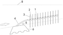
Fig. 1 is a schematic structural view of a marine erosion prevention system according to an embodiment of the present application.
Fig. 2 is a schematic structural view of the suspended funnel-shaped sea sand trapping cage net in fig. 1.
Fig. 3 is a schematic view of a connection structure of the support of the barrier in fig. 2 and the sand transporting and blocking plate.
Fig. 4 is a side view of the pedestal projecting mounting post of the baffle of fig. 2.
FIG. 5 is a side view of the mounting slot of the base depression of the baffle of FIG. 2.
Figure 6 is a schematic diagram of the structure of the trapping cage net of figure 2.
Fig. 7 is a schematic view of the structure of the brush column of fig. 1.
Fig. 8 is a top view of the brush column of fig. 1.
FIG. 9 is a schematic view of an arrangement of the brush columns of FIG. 1.
FIG. 10 is a schematic view of another arrangement of the brush columns of FIG. 1.
Fig. 11 is a schematic structural view of the n-shaped suspended storage type sand-fixing barrier in fig. 1.
Fig. 12 is a circular rubber sheet of the figure 11 extendable post and stationary coil-wound three-dimensional net.
Description of reference numerals: 1. a funnel; 2. connecting a net; 3. a column; 4. a sand transporting and blocking plate; 41. a first securing latch; 411. a first extension pole; 42. a second securing latch; 412. a second extension pole; 5. a pillar; 6. a base; 61. dovetail mortise and tenon type mounting columns; 62. mounting grooves; 7. a sea bed surface; 8. a highest tide line; 9. connecting ropes; 101. a first connecting ring; 102. a second connection ring; 11. a connecting rod; 12. a brush column; 121. a support pillar; 122. a filiform brush; 123. tow; 13. kelp; 131. building blocks; 132. a breeding rope; n-shaped suspended storage type sand-fixing barriers; 151. a wire coil wound three-dimensional mesh; 152. the supporting column can be lengthened; 153. a circular rubber sheet; 154. a hanging-down part; 155. a main body portion; 156 the ground; 16. beach.
Detailed Description
The present invention will be more fully understood from the following detailed description, which should be read in conjunction with the accompanying drawings. Detailed embodiments of the present invention are disclosed herein; however, it is to be understood that the disclosed embodiments are merely exemplary of the utility model, which can be embodied in various forms. Therefore, specific functional details disclosed herein are not to be interpreted as limiting, but merely as a basis for the claims and as a representative basis for teaching one skilled in the art to variously employ the present invention in virtually any appropriately detailed embodiment.
The suspended funnel-shaped sea sand trapping cage net provided by the embodiment of the utility model has the advantages that the baffle can prevent the front side of sea waves from directly impacting a seabed, and sediment passes through the surface of the baffle and falls into a sea bed surface at the bottom of the funnel along with water flow and waves; the collecting cage net is only open towards the bank to form a semi-closed sand collecting space, and the collecting cage net and the semi-closed sand collecting space are combined to form a suspended funnel-shaped sea sand collecting cage net which can collect sediments transmitted towards the bank and retreated into the sea along with the waves and the tides; after the sand collecting space is full of sand, the height of a fixed point between the connecting rope and the stand column can be lifted, and the mode of installing the extension rod under the fixing bolt is provided, so that the cage net and the baffle are integrally lifted, and the sustainable utilization of the device is realized.
The utility model provides a coastal erosion protection system which comprises a giant kelp planting area, a suspended funnel-shaped sea sand trapping cage net, a brush column and an n-shaped suspended storage type sand fixing barrier which are sequentially arranged along the ocean direction to the land direction, wherein the giant kelp planting area, the suspended funnel-shaped sea sand trapping cage net, the brush column and the n-shaped suspended storage type sand fixing barrier are respectively parallel to a coastline and are arranged in a plurality of ways.
In some preferred embodiments, the kelp planting area is distributed with a culture rope vertically arranged in a water area with the depth of 5-20m below the lowest tide level, and the culture rope is used for planting kelp; preferably, 15-20 artificially cultured 15 cm-long megalophyta juvenile algae are clamped in each 2 m-long breeding rope; preferably, the diameter of the breeding rope is 3-4cm, the length of the breeding rope is 5-20m, and the bottom of the breeding rope is fixed on a building block buried in a seabed.
In some preferred embodiments, the suspended funnel-shaped sea sand collecting cage net comprises more than one baffle and a collecting cage net, wherein the baffle is arranged on the side, close to the collecting cage net, facing the sea through a fixing mechanism; the catching cage net comprises a connecting net, a funnel and connecting ropes, wherein the connecting net is provided with the connecting ropes at least used for reinforcing the connecting net, the connecting net is divided into a plurality of connecting net units at equal intervals by the connecting ropes, and the funnel is distributed on each connecting net unit; the baffle comprises a sand conveying and blocking plate and a base, and the sand conveying and blocking plate is fixedly connected with the base through a pillar.
In some preferred embodiments, the suspended funnel-shaped sea sand capture cage mesh is disposed in a banded region between intertidal zones and between 20m and 100m from the highest tide line.
In some preferred embodiments, the fixing mechanism includes a first connecting ring provided on the top of the sand transporting and blocking plate, a plurality of second connecting rings provided on a sea-facing side of the connecting net, and a connecting rod passing through the first and second connecting rings.
In some preferred embodiments, the edge of the funnel is provided with a small hole, and the funnel is bound and fixed on the connecting net through the small hole.
In some preferred embodiments, a vertical column is further arranged at the intersection of the connecting ropes, and the suspended funnel-shaped sea sand trapping cage net is fixed on the sea bed surface through the vertical column.
In some preferred embodiments, the width of the trapping cage net in the direction perpendicular to the shoreline is 5-10 m.
In some preferred embodiments, the connecting web is an HDPE web having a porosity of 10 to 20%.
In some preferred embodiments, the funnel is made from a HDPE sheet hot melt laminated film.
In some preferred embodiments, each funnel has an upper caliber of 15-25cm, a lower caliber of 3-5cm and a height of 15-20 cm.
In some preferred embodiments, the posts have a diameter of 3-6cm and a height of 1.5-2m, such that the trapping cage net is suspended at a height of 50-100cm above the surface of the sea bed.
In some preferred embodiments, the sand transporting and blocking plate is in a smooth streamline structure.
In some preferred embodiments, the support column and the sand transporting and blocking plate are of an integrally formed structure poured by reinforced concrete, and the support column is arranged in the middle of the sand transporting and blocking plate and is positioned on the shore-facing side of the sand transporting and blocking plate.
In some preferred embodiments, the bottom of the sand transporting and blocking plate and the bottom of the pillar are respectively provided with a fixed bolt and an extension rod matched with the fixed bolt; the base is formed by connecting a plurality of building blocks along the shore line direction, and is connected through forked tail mortise type erection column and mounting groove between two adjacent building blocks and forms an organic whole, and every building block top have with extension rod bottom complex sunken mounting hole.
In some preferred embodiments, the width of the sand conveying and blocking plate in the direction perpendicular to the shoreline is 1.5-2.5m, the thickness is 5-10cm, and the height is 50-100 cm.
In some preferred embodiments, the brush columns are arranged in the intertidal zone along the parallel direction of the coast in a zigzag or wave-shaped manner.
In some preferred embodiments, two adjacent brush columns are close to each other, and the distance between each track is 1-3 m.
In some preferred embodiments, the brush column comprises a support column and a filamentous brush fixed to the support column, the filamentous brush comprising a plurality of tows densely distributed along the length of the support column, both ends of each tow extending to both sides of the support column.
In some preferred embodiments, the filamentous brush has a diameter of 25-50cm and a length of 60-100 cm.
In some preferred embodiments, the length of each tow end extending to both sides of the support post is 10-20 cm.
In some preferred embodiments, the tow is composed of a plurality of nylon filaments having a diameter of 0.5-1mm and a tow diameter of 3-5 mm.
In some preferred embodiments, the support column has a diameter of 5-10cm, a length of 1.3-1.7m, and a bottom portion that is buried to a depth of 70cm into the seabed.
In some preferred embodiments, the support post may comprise, but is not limited to, a solid cylinder of PVC.
In some preferred embodiments, the n-shaped suspended storage sand-fixation barrier is arranged on the beach above the highest tide level line perpendicular to the main wind direction.
In some preferred embodiments, the n-shaped suspended storage type sand stabilization barrier comprises a wire loop winding type three-dimensional net and a plurality of connectable posts movably connected with the wire loop winding type three-dimensional net, wherein the wire loop winding type three-dimensional net is laid along the horizontal direction, and two side edge portions naturally droop, so that a structure with an n-shaped lateral section is formed.
In some preferred embodiments, the main body part of the wire coil wound three-dimensional net is 20-50cm away from the ground, and the lower edge of the hanging part is 10-20cm away from the ground.
In some preferred embodiments, each extendable post is sleeved with two circular rubber sheets, the wire coil wound three-dimensional net is fixed between the two circular rubber sheets, and the circular rubber sheets have the thickness of 1-2cm, the inner diameter of 2-3cm and the outer diameter of 5-10 cm.
In some preferred embodiments, the n-shaped suspended storage type sand fixing barriers are arranged in a plurality of channels, and the distance between two adjacent n-shaped suspended storage type sand fixing barriers is 10-40 m.
In some preferred embodiments, when the top of the sand accumulation surface is close to the bottom surface of the wire coil winding type three-dimensional net main body, the wire coil winding type three-dimensional net connected to the extendable column is lifted, or the height of the extendable column is lifted, or another extendable column is connected to the top end of the extendable column, so that the n-shaped suspended storage sand-fixing barrier is lifted.
According to the coastal erosion protection system provided by the embodiment of the utility model, in seawater, the giant kelp can reduce the energy of ocean currents and wave tides in a deep water area, the cage net is trapped to reduce the waves near the lowest tide line, the sediment deposition of the sediment in the cage net is promoted, the brush columns mainly break the wave zone between the tides, and the waves are weakened, and sand particles are filtered and deposited; on the sand beach on the high tide line, the n-shaped suspension warehouse type sand stabilization barrier plays a role in fixing the quicksand for a long time; the method comprises the following steps of four measures with functions, wherein the measures are arranged in a plurality of ways parallel to a coastline according to the topographic conditions of a beach, and are combined with each other to form a coast erosion protection system, so that the supply of water sand and wind sand sediments to the shore is larger than the loss to the sea from a near-shore seabed to a land beach, the siltation of the seabed and the beach is promoted, the elevation of the sea bed surface and the beach is continuously improved, the wave energy is weakened, and the occurrence of coast erosion is inhibited; especially for sandy shorelines, the method is an effective measure for comprehensive treatment of water sand and wind sand near the shore.
Examples
Referring to fig. 1, an embodiment of the present invention provides a coastal erosion protection system, which includes a kelp planting region, a suspended funnel-shaped sea sand trapping cage net, a brush column 12, and an n-shaped suspended storage type sand-fixing barrier 15, which are sequentially arranged along a sea direction toward a land direction, wherein the kelp planting region, the suspended funnel-shaped sea sand trapping cage net, the brush column 12, and the n-shaped suspended storage type sand-fixing barrier 15 are respectively parallel to a coastline and are arranged in multiple ways.
In the specific implementation process, the kelp planting area is distributed with culture ropes 132 vertically distributed in a water area with the depth of 5-20m below the lowest tide level, and the culture ropes 132 are used for planting kelp 13; preferably, 15-20 artificially cultured 15 cm-long kelp julians are respectively clamped in each 2 m-long cultivation rope 132; the diameter of the breeding rope 132 is 3-4cm, the length is 5-20m, and the bottom of the breeding rope 132 is fixed on the building block 131 buried in the seabed.
Referring to fig. 2-6, the suspended funnel-shaped sea sand collecting cage comprises more than one baffle and a collecting cage, wherein the baffle is arranged on the side close to the collecting cage and facing the sea through a fixing mechanism; the catching cage net comprises a connecting net 2, a funnel 1 and connecting ropes 9, the connecting net 2 is provided with the connecting ropes 9, the connecting ropes 9 are at least used for reinforcing the connecting net 2, the connecting net 2 is divided into a plurality of connecting net units at equal intervals by the connecting ropes 9, and the funnels 1 are respectively distributed on the connecting net units; the baffle comprises a sand conveying and blocking plate 4 and a base 6, and the sand conveying and blocking plate 4 is fixedly connected with the base 6 through a pillar 5.
In the specific implementation process, the suspended funnel-shaped sea sand trapping cage net is arranged in a strip-shaped area which is in an intertidal zone and is 820-100 m away from the highest tide line, and the fixing mechanism comprises a first connecting ring 101 arranged at the top of the sand conveying and blocking plate 4, a plurality of second connecting rings 102 arranged on the sea-facing side surface of the connecting net 2 and a connecting rod 11 penetrating through the first connecting ring 101 and the second connecting rings 102; the edge of the funnel 1 is provided with a small hole, and the funnel 1 is bound and fixed on the connecting net 2 through the small hole; the cross part of the connecting rope 9 is also provided with an upright post 3, and the suspended funnel-shaped sea sand trapping cage net is fixed on the sea bed surface 7 through the upright post 3.
In the implementation process, the width of the trapping cage net along the direction vertical to the shoreline is 5-10m, the connecting net 2 is an HDPE net with the porosity of 10-20%, the funnels 1 are made of HDPE plates through hot-melt film pressing, the upper caliber of each funnel is 15-25cm, the lower caliber of each funnel is 3-5cm, the height of each funnel is 15-20cm, the diameter of each upright post 3 is 3-6cm, and the height of each upright post is 1.5-2m, so that the trapping cage net is suspended at the height of 50-100cm above the surface of the sea bed; the sand conveying and blocking plate 4 is of a smooth streamline structure, the width of the sand conveying and blocking plate 4 in the direction vertical to the shoreline is 1.5-2.5m, the thickness is 5-10cm, and the height is 50-100 cm; the support 5 and the sand transporting and blocking plate 4 are of an integrally formed structure poured by reinforced concrete, and the support 5 is arranged in the middle of the sand transporting and blocking plate 4 and is positioned on the shore-facing side of the sand transporting and blocking plate 4. The bottom parts of the sand transporting and blocking plate 4 and the pillar 5 are respectively provided with a first fixing bolt 41 and a second fixing bolt 42, and a first extension rod 411 and a second extension rod 412 which are respectively matched with the first fixing bolt 41 and the second fixing bolt 42; the base 6 is formed by connecting a plurality of building blocks along the shore line direction, and is connected through dovetail mortise-tenon type mounting post 61 and mounting groove 62 between two adjacent building blocks to form an organic whole, and every building block top has with first gim peg 41 and second gim peg 42 (or first extension rod 411 and second extension rod 412 pole) bottom complex sunken mounting hole.
Referring to fig. 9 to 10, the brush columns 12 are arranged in an intertidal zone in a zigzag or wavy manner in a plurality of rows along a parallel direction of a coast, two adjacent brush columns 12 are abutted against each other, and a distance between each row is 1 to 3m, referring to fig. 7 and 8, the brush columns 12 include a support column 121 and a filament brush 122 fixed to the support column 121, the filament brush 122 includes a plurality of filament bundles 123 densely distributed along a length direction of the support column 121, both ends of each filament bundle 123 extend to both sides of the support column 121, a diameter of the filament brush 122 is 25 to 50cm, a length of the filament brush 122 is 60 to 100cm, both ends of each filament bundle 123 extend to both sides of the support column 121 in a length of 10 to 20cm, the filament bundles 123 are composed of a plurality of nylon filaments, a diameter of the nylon filaments is 0.5 to 1mm, a diameter of the filament bundles 123 is 3 to 5mm, a diameter of the support column 121 is 5 to 10cm, the length is 1.3-1.7m, and the bottom is buried into the seabed to a depth of 70 cm. In the implementation process, the support column 121 is a solid cylinder made of PVC.
Referring to fig. 11, the n-shaped suspended storage type sand-fixing barrier 15 is arranged on the beach 16 above the highest tide level line 8 perpendicular to the main wind direction, the n-shaped suspended storage type sand-fixing barrier 15 comprises a wire coil wound three-dimensional net 151 and a plurality of extendable columns 152 movably connected with the wire coil wound three-dimensional net 151, wherein the wire coil wound three-dimensional net 151 is laid along the horizontal direction and the two side edge portions naturally droop, so that a structure with an n-shaped lateral section is formed; the distance between the main body part 155 of the wire coil winding type three-dimensional net 151 and the ground 156 is 20-50cm, and the distance between the lower edge of the drooping part 154 and the ground 156 is 10-20 cm; each extendable post 152 is sleeved with two circular rubber sheets 153, as shown in fig. 12, the wire coil wound three-dimensional net 151 is fixed between the two circular rubber sheets 153, and the circular rubber sheets 153 have a thickness of 1-2cm, an inner diameter of 2-3cm, and an outer diameter of 5-10 cm.
In the specific implementation process, the n-shaped suspended storage type sand fixing barriers 15 are arranged in a plurality of channels, and the distance between two adjacent n-shaped suspended storage type sand fixing barriers 15 is 10-40 m; when the top of the sand accumulation surface is close to the bottom surface of the wire coil winding type three-dimensional net main body, the wire coil winding type three-dimensional net 151 connected to the connectable length column 152 is lifted, or the height of the connectable length column 152 is lifted, or another connectable length column 152 is connected to the top end of the connectable length column 152, so that the n-shaped suspended storage type sand-fixing barrier 15 is lifted.
In addition, the utility model discloses a still refer to the aforesaid embodiment, have tested with other raw materials, process operation, process conditions mentioned in this specification to all obtain comparatively ideal result.
While the utility model has been described with reference to illustrative embodiments, it will be understood by those skilled in the art that various other changes, omissions and/or additions may be made and substantial equivalents may be substituted for elements thereof without departing from the spirit and scope of the utility model. In addition, many modifications may be made to adapt a particular situation or material to the teachings of the utility model without departing from its scope. Therefore, it is intended that the utility model not be limited to the particular embodiment disclosed for carrying out this invention, but that the utility model will include all embodiments falling within the scope of the appended claims. Moreover, unless specifically stated any use of the terms first, second, etc. do not denote any order or importance, but rather the terms first, second, etc. are used to distinguish one element from another.
Claims (10)
1. The utility model provides a coast erosion protection system, its characterized in that includes that the huge algae that lays in proper order to land direction along the marine direction plants district, floated hourglass hopper-shaped sea sand entrapment cage net, brush post and the solid sand barrier of n shape suspension storehouse storage formula, the huge algae is planted district, floated hourglass hopper-shaped sea sand entrapment cage net, brush post and the solid sand barrier of n shape suspension storehouse storage formula and is on a parallel with the coastline respectively and is the multichannel setting.
2. The coastal erosion protection system of claim 1, characterized in that: the kelp planting area is provided with culture ropes vertically distributed in a water area with the depth of 5-20m below the lowest tide level, and the culture ropes are used for planting kelp; preferably, 15-20 artificially cultured 15 cm-long megalophyta juvenile algae are clamped in each 2 m-long breeding rope; preferably, the diameter of the breeding rope is 3-4cm, the length of the breeding rope is 5-20m, and the bottom of the breeding rope is fixed on a building block buried in a seabed.
3. The coastal erosion protection system of claim 1, characterized in that: the suspended funnel-shaped sea sand trapping cage net comprises more than one baffle and a trapping cage net, and the baffle is arranged on the side, close to the trapping cage net, facing the sea through a fixing mechanism; the catching cage net comprises a connecting net, a funnel and connecting ropes, wherein the connecting net is provided with the connecting ropes at least used for reinforcing the connecting net, the connecting net is divided into a plurality of connecting net units at equal intervals by the connecting ropes, and the funnel is distributed on each connecting net unit; the baffle comprises a sand conveying and blocking plate and a base, and the sand conveying and blocking plate is fixedly connected with the base through a pillar.
4. The coastal erosion protection system of claim 3, characterized in that: the suspended funnel-shaped sea sand trapping cage net is arranged in a strip-shaped area which is between the intertidal zone and 20m to 100m away from the highest tide line;
and/or the fixing mechanism comprises a first connecting ring arranged at the top of the sand conveying and blocking plate, a plurality of second connecting rings arranged on the sea side surface of the connecting net and a connecting rod penetrating through the first connecting ring and the second connecting rings; and/or the edge of the funnel is provided with a small hole, and the funnel is bound and fixed on the connecting net through the small hole; and/or an upright post is also arranged at the cross part of the connecting rope, and the suspended funnel-shaped sea sand trapping cage net is fixed on the sea bed surface through the upright post.
5. The coastal erosion protection system of claim 4, characterized in that: the width of the trapping cage net along the direction vertical to the shoreline is 5-10 m; and/or the connecting net adopts an HDPE net with the porosity of 10-20%; and/or the funnel is made of HDPE plate hot-melt laminated film; and/or the upper caliber of each funnel is 15-25cm, the lower caliber is 3-5cm, and the height is 15-20 cm; and/or the diameter of the upright post is 3-6cm, the height of the upright post is 1.5-2m, and the trapping cage net is suspended above the sea bed surface by 50-100 cm.
6. The coastal erosion protection system of claim 3, characterized in that: the sand conveying and blocking plate is of a smooth streamline structure; and/or the support column and the sand conveying and blocking plate are of an integrally formed structure poured by reinforced concrete, and the support column is arranged in the middle of the sand conveying and blocking plate and is positioned on the shore-facing side of the sand conveying and blocking plate; and/or the bottom of the sand conveying and blocking plate and the bottom of the support are respectively provided with a fixed bolt and an extension rod matched with the fixed bolt; the base is formed by connecting a plurality of building blocks along the shore line direction, and is connected through forked tail mortise type erection column and mounting groove between two adjacent building blocks and forms an organic whole, and every building block top have with extension rod bottom complex sunken mounting hole.
7. The coastal erosion protection system of claim 6, characterized in that: the width of the sand conveying and blocking plate along the direction vertical to the shoreline is 1.5-2.5m, the thickness is 5-10cm, and the height is 50-100 cm.
8. The coastal erosion protection system of claim 1, characterized in that: the brush columns are distributed in a zigzag or wavy manner in the intertidal zone along the parallel direction of the coast; and/or the two adjacent brush columns are mutually abutted, and the distance between every two adjacent brush columns is 1-3 m; and/or the hairbrush column comprises a support column and a filamentous hairbrush fixed on the support column, the filamentous hairbrush comprises a plurality of tows which are densely distributed along the length direction of the support column, and two ends of each tow extend to two sides of the support column; and/or the diameter of the filamentous brush is 25-50cm, and the length of the filamentous brush is 60-100 cm; and/or the length of the two ends of each tow extending to the two sides of the support column is 10-20 cm; and/or the tows are composed of a plurality of nylon filaments, the diameter of the nylon filaments is 0.5-1mm, and the diameter of the tows is 3-5 mm; and/or the diameter of the support column is 5-10cm, the length is 1.3-1.7m, and the depth of the bottom embedded into the seabed is 70 cm; and/or the support column comprises a solid cylinder made of PVC.
9. The coastal erosion protection system of claim 1, characterized in that: the n-shaped suspended storage type sand stabilization barrier is arranged on a beach above the highest tide level line in a manner of being vertical to the main wind direction, and/or comprises a wire coil wound three-dimensional net and a plurality of connectable long columns movably connected with the wire coil wound three-dimensional net, wherein the wire coil wound three-dimensional net is laid along the horizontal direction, and the edge parts of two sides of the wire coil wound three-dimensional net naturally droop, so that a structure with an n-shaped lateral section is formed.
10. The coastal erosion protection system of claim 9, characterized in that: the distance between the main body part of the wire coil winding type three-dimensional net and the ground is 20-50cm, and the distance between the lower edge of the downward hanging part and the ground is 10-20 cm;
and/or, each connectable post is sleeved with two circular rubber sheets, the wire coil winding type three-dimensional net is fixed between the two circular rubber sheets, and the circular rubber sheets have the thickness of 1-2cm, the inner diameter of 2-3cm and the outer diameter of 5-10 cm;
and/or the n-shaped suspended storage type sand fixing barriers are arranged in a plurality of channels, and the distance between two adjacent n-shaped suspended storage type sand fixing barriers is 10-40 m;
and/or when the top of the sand accumulation surface is close to the bottom surface of the wire coil winding type three-dimensional net main body part, the wire coil winding type three-dimensional net connected to the extendable column is lifted in height, or the height of the extendable column is lifted, or the top end of the extendable column is connected with another extendable column, so that the n-shaped suspended storage type sand stabilization barrier is lifted.
Priority Applications (1)
| Application Number | Priority Date | Filing Date | Title |
|---|---|---|---|
| CN202120791675.8U CN215948062U (en) | 2021-04-16 | 2021-04-16 | Coastal erosion protection system |
Applications Claiming Priority (1)
| Application Number | Priority Date | Filing Date | Title |
|---|---|---|---|
| CN202120791675.8U CN215948062U (en) | 2021-04-16 | 2021-04-16 | Coastal erosion protection system |
Publications (1)
| Publication Number | Publication Date |
|---|---|
| CN215948062U true CN215948062U (en) | 2022-03-04 |
Family
ID=80505872
Family Applications (1)
| Application Number | Title | Priority Date | Filing Date |
|---|---|---|---|
| CN202120791675.8U Active CN215948062U (en) | 2021-04-16 | 2021-04-16 | Coastal erosion protection system |
Country Status (1)
| Country | Link |
|---|---|
| CN (1) | CN215948062U (en) |
Cited By (1)
| Publication number | Priority date | Publication date | Assignee | Title |
|---|---|---|---|---|
| CN117702674A (en) * | 2024-02-06 | 2024-03-15 | 交通运输部天津水运工程科学研究所 | Ecological belt construction device for reducing sand beach mud |
-
2021
- 2021-04-16 CN CN202120791675.8U patent/CN215948062U/en active Active
Cited By (2)
| Publication number | Priority date | Publication date | Assignee | Title |
|---|---|---|---|---|
| CN117702674A (en) * | 2024-02-06 | 2024-03-15 | 交通运输部天津水运工程科学研究所 | Ecological belt construction device for reducing sand beach mud |
| CN117702674B (en) * | 2024-02-06 | 2024-04-05 | 交通运输部天津水运工程科学研究所 | Ecological belt construction device for reducing sand beach mud |
Similar Documents
| Publication | Publication Date | Title |
|---|---|---|
| CN102666999A (en) | Wave suppressor and sediment collection system | |
| CN102587317B (en) | Composite ecological component for weakening waves and controlling, stopping and guiding algae, manufacturing method and application thereof | |
| CN107988999B (en) | Hydrodynamic self-lifting hydro-fluctuation belt wetland ecological management system and construction method thereof | |
| CN215948062U (en) | Coastal erosion protection system | |
| CN110184994A (en) | A kind of combined type submerged breakwater structure and preparation method thereof | |
| CN100445470C (en) | Underwater groins system for growing various living things | |
| CN111636373A (en) | Oyster reef row and sea dike foot protection device and dike foot protection method | |
| CN109349165B (en) | Marine ranch | |
| CN110552318A (en) | Plank road type ecological revetment | |
| CN103069080B (en) | New use of triangular cylinder | |
| CN115217064A (en) | Suspended funnel-shaped sea sand collecting cage net and coastal erosion protection system | |
| Iskander | Environmental friendly methods for the Egyptian coastal protection | |
| CN112359775A (en) | Ecological zone construction method for reducing waves and sandy beach argillization | |
| CN107938592B (en) | Ecological transformation structure of linear type urban river | |
| CN109252487B (en) | I-shaped dam for ecological restoration and protection and ecological construction method thereof | |
| CN214363265U (en) | Flexible protection system for promoting silt and making land near nature | |
| CN112106713B (en) | Semi-suspension type artificial fish reef | |
| CN112523161B (en) | Device for beach maintenance, wave dissipation and floater collection | |
| JPWO2002099202A1 (en) | Hydropower generation method | |
| JP4550231B2 (en) | Bottom sediment movement control method | |
| CN105544462B (en) | A kind of river disappears the bank protection method of wave | |
| CN108951540A (en) | A kind of collection algae gear algae leads algae enclosure system | |
| CN211340638U (en) | Special sand protecting pipe for buried beach maintenance and sand protection | |
| CN113136833A (en) | Ecological assembled spur dike and construction method thereof | |
| CN215948060U (en) | Coastal erosion prevention and control system |
Legal Events
| Date | Code | Title | Description |
|---|---|---|---|
| GR01 | Patent grant | ||
| GR01 | Patent grant |