CN215712855U - Production line for preparing solid fuel from kitchen waste - Google Patents
Production line for preparing solid fuel from kitchen waste Download PDFInfo
- Publication number
- CN215712855U CN215712855U CN202120357484.0U CN202120357484U CN215712855U CN 215712855 U CN215712855 U CN 215712855U CN 202120357484 U CN202120357484 U CN 202120357484U CN 215712855 U CN215712855 U CN 215712855U
- Authority
- CN
- China
- Prior art keywords
- crushing
- kitchen waste
- smoke
- shell
- solid fuel
- Prior art date
- Legal status (The legal status is an assumption and is not a legal conclusion. Google has not performed a legal analysis and makes no representation as to the accuracy of the status listed.)
- Active
Links
Images


Classifications
-
- Y—GENERAL TAGGING OF NEW TECHNOLOGICAL DEVELOPMENTS; GENERAL TAGGING OF CROSS-SECTIONAL TECHNOLOGIES SPANNING OVER SEVERAL SECTIONS OF THE IPC; TECHNICAL SUBJECTS COVERED BY FORMER USPC CROSS-REFERENCE ART COLLECTIONS [XRACs] AND DIGESTS
- Y02—TECHNOLOGIES OR APPLICATIONS FOR MITIGATION OR ADAPTATION AGAINST CLIMATE CHANGE
- Y02E—REDUCTION OF GREENHOUSE GAS [GHG] EMISSIONS, RELATED TO ENERGY GENERATION, TRANSMISSION OR DISTRIBUTION
- Y02E50/00—Technologies for the production of fuel of non-fossil origin
- Y02E50/10—Biofuels, e.g. bio-diesel
-
- Y—GENERAL TAGGING OF NEW TECHNOLOGICAL DEVELOPMENTS; GENERAL TAGGING OF CROSS-SECTIONAL TECHNOLOGIES SPANNING OVER SEVERAL SECTIONS OF THE IPC; TECHNICAL SUBJECTS COVERED BY FORMER USPC CROSS-REFERENCE ART COLLECTIONS [XRACs] AND DIGESTS
- Y02—TECHNOLOGIES OR APPLICATIONS FOR MITIGATION OR ADAPTATION AGAINST CLIMATE CHANGE
- Y02E—REDUCTION OF GREENHOUSE GAS [GHG] EMISSIONS, RELATED TO ENERGY GENERATION, TRANSMISSION OR DISTRIBUTION
- Y02E50/00—Technologies for the production of fuel of non-fossil origin
- Y02E50/30—Fuel from waste, e.g. synthetic alcohol or diesel
Abstract
The utility model discloses a production line for preparing solid fuel by kitchen waste, which relates to the technical field of kitchen waste treatment and comprises a storage bin, a coarse crushing device, a dehydration and degreasing device and a high-temperature crushing and drying device which are sequentially connected; the crushing and drying mechanism comprises a hot blast stove and a crushing and drying mechanism, and an air outlet of the hot blast stove is communicated with the crushing and drying mechanism; the air outlet of the crushing and drying mechanism is communicated with the storage bin through the flue gas recovery system. The utility model discloses a coarse crushing device, dehydration degreaser and crushing stoving mechanism that set gradually, smash the stoving through coarse crushing, dehydration degrease, high temperature with kitchen garbage in proper order, obtain powdered solid fuel, need not slurrying, many times dry, its processing procedure is few, the treatment effeciency is high, can realize kitchen garbage's rapid processing.
Description
Technical Field
The utility model relates to the technical field of flue gas treatment equipment, in particular to a production line for preparing solid fuel from kitchen waste.
Background
The kitchen waste is food residues of restaurants, unit canteens and the like and processing process wastes of fruits, vegetables, meat, grease, pastries and the like in the kitchen, and also contains household kitchen waste, so that the kitchen waste contains abundant starch, cellulose, protein, fat, inorganic salt and the like, can be prepared into solid fuel with higher combustion value after being dried, realizes recycling of the kitchen waste and reduces environmental pollution.
The existing solid fuel prepared from kitchen waste is generally prepared by adopting the modes of crushing and pulping the waste, then gradually drying and curing, and the solid fuel is wide in equipment floor area, long in treatment time, small in treatment amount and high in unit treatment cost, and cannot meet the requirement of the treatment amount of urban kitchen waste.
SUMMERY OF THE UTILITY MODEL
The utility model provides an aim at overcome among the prior art when kitchen garbage prepares into solid waste equipment area big, the processing time is long, the problem that the handling capacity is little, provide a production line of kitchen garbage preparation solid fuel, adopt the coarse crushing device that sets gradually, dehydration degreaser and crushing stoving mechanism, with kitchen garbage in proper order through coarse crushing, the dehydration degrease, high temperature crushing stoving, obtain powdered solid fuel, need not slurrying, many times drying, its processing procedure is few, the treatment effeciency is high, can realize kitchen garbage's rapid draing.
In order to realize the purpose of the utility model, the application provides the following technical scheme: a production line for preparing solid fuel by kitchen waste comprises a storage bin, a coarse crushing device, a dehydration and degreasing device and a high-temperature crushing and drying device which are sequentially connected; the high-temperature crushing and drying device comprises a hot blast stove and a crushing and drying mechanism, and an air outlet of the hot blast stove is communicated with the crushing and drying mechanism; the air outlet of the crushing and drying mechanism is communicated with the storage bin through the flue gas recovery system.
In the technical scheme, the kitchen waste is subjected to coarse particle kitchen waste with the water content not more than 60% through a coarse crushing device and a dehydration and degreasing device, and then is crushed and dried simultaneously through a crushing and drying mechanism without pulping; meanwhile, a hot blast stove is adopted to provide hot air for drying the kitchen waste for the crushing and drying mechanism of the crushing and drying mechanism, and the kitchen waste is rapidly dried through high-temperature hot air to obtain powder fuel; the hot air is wrapped up in and is being carried powdered fuel and realize the separation of powdered fuel and hot-air in flue gas recovery system, and the hot-air of isolating provides preheating heat for the feed bin, realizes preheating of kitchen garbage, improves heat utilization ratio to shorten the processing of kitchen garbage and it is long, improvement treatment effeciency.
Further, the feed bin includes the storehouse body and is the heliciform or S-shaped setting and preheats the passageway on the storehouse body inside wall, flue gas recovery system with preheat the passageway intercommunication. The high-temperature flue gas in the flue gas recovery system realizes the preheating of the kitchen waste through the preheating channel.
Furthermore, the flue gas recovery system comprises a return air channel, a water inlet pipeline, a smoke eliminator, an impeller and a water collecting tank; one end of the air return channel is communicated with an air outlet of the crushing and drying mechanism, the other end of the air return channel is connected with the smoke eliminator, and the water inlet pipeline is communicated with the smoke eliminator; the impeller is arranged in the water collecting tank and is communicated with the outlet of the smoke eliminator; the water collecting tank is provided with a liquid supply pipeline communicated with the preheating channel.
In the technical scheme, the water absorption crushing and drying mechanism is adopted to crush the high-temperature flue gas discharged from the drying mechanism, and the water heated after absorbing the high-temperature flue gas is used for preheating the kitchen waste, so that the heat utilization rate is improved; meanwhile, the problems of short service life of the storage bin, local coking and the like caused by directly preheating the kitchen waste by high-temperature flue gas are avoided; in addition, in the technical scheme, the water and the high-temperature flue gas are fully mixed through the smoke eliminator, and the absorption capacity and the absorption effect of the high-temperature flue gas are improved.
Because it is very high to smash stoving mechanism crushing stoving mechanism in exhaust high temperature flue gas temperature, if directly be used for preheating of kitchen garbage, it is high to the heat-resisting requirement of feed bin, and at this moment the kitchen garbage contains a large amount of moisture, grease and volatilizable gas in addition, and direct high temperature preheats, leads to a large amount of moisture to volatilize easily, leads to kitchen garbage's peculiar smell scattered, influences kitchen garbage's treatment place operational environment. In addition, the high temperature flue gas also needs to be treated before being discharged. Therefore, the water is adopted to absorb the heat of the high-temperature flue gas and the smoke dust and harmful gases in the high-temperature flue gas to obtain the treated water with the increased temperature, and then the treated water is used for preheating the kitchen waste, so that the temperature of the high-temperature flue gas is reduced, and meanwhile, the smoke abatement treatment of the high-temperature flue gas can be realized.
Furthermore, the return air channel comprises an ascending pipeline, a cyclone separator and a flue gas recovery pipeline which are connected in sequence; one end of the ascending pipeline is connected with an air outlet of the crushing and drying mechanism, and the other end of the ascending pipeline is connected with a fluid inlet of the cyclone separator; one end of the smoke recovery channel is connected with the exhaust port of the cyclone separator, and the other end of the smoke recovery channel is connected with the smoke eliminator. The cyclone separator is connected to the air outlet through the ascending pipeline, hot air and kitchen waste particles are separated, and collection of the kitchen waste particles is achieved.
Furthermore, the ascending pipeline is of a funnel-shaped structure with a large upper part and a small lower part, so that the air pressure of hot air is reduced, the speed is reduced, and the drying effect is improved.
Furthermore, the smoke eliminator comprises a smoke eliminating shell, a smoke eliminating device and a fourth driving motor, wherein the smoke eliminating device and the fourth driving motor are installed in the smoke eliminating shell; the smoke abatement shell is provided with inlets for smoke and water to flow in respectively; the inlet is respectively communicated with the smoke recovery channel and the water inlet pipeline, and the outlet is also arranged on the smoke abatement shell and is communicated with the impeller; the smoke abatement device comprises a bottom plate, a top plate and at least two annular blade sets arranged between the bottom plate and the top plate; all the annular blade sets are coaxially arranged along the axis of the bottom plate, and two ends of all the annular blade sets are hermetically connected with the bottom plate and the top plate; each annular blade group comprises a plurality of blades which are arrayed in an annular mode along the axis of the bottom plate, and a space is reserved between every two adjacent blades of each annular blade group; the top plate is provided with a liquid inlet, the liquid inlet is in sealing connection with an inlet through a pipeline, and the inner diameter of the liquid inlet is smaller than that of the annular blade group with the minimum inner diameter; and a gap is formed between the smoke abatement shell and the annular blade group on the outermost side.
The smoke and water enter the inlet of the smoke eliminator along the inlet on the smoke eliminator shell, so that the high-temperature smoke and water enter the middle of the smoke eliminator, and under the centrifugal action of the smoke eliminator rotating at high speed, the smoke and water are quickly and uniformly converged into the gap between the outermost annular blade group and the smoke eliminator shell from the gap between the outermost annular blade group and the smoke eliminator shell, and then are converged into the outlet from the gap between the outermost annular blade group and the smoke eliminator shell, and the smoke eliminator is removed. When the flue gas flows fast in the annular blade group, cut into a plurality of microbubbles by a plurality of blades of constituteing the annular blade group, equally, water is also cut the atomizing, makes flue gas and water fully contact, mixes, makes dust, granule etc. fully absorb water in the flue gas, and the gas of dissolving in water is absorbed by water, realizes the absorption of harmful substance in the flue gas.
Further, the coarse crushing device and the dehydration and degreasing device are integrated into an integrated sorting, dehydration and degreasing integrated device; integrative device of dehydration degrease is selected separately to integration includes: the device comprises a shell, a sorting and crushing section and a dehydration and degreasing section, wherein the sorting and crushing section and the dehydration and degreasing section are arranged in the shell; the sorting and crushing section comprises a rotary screen and a coarse crushing device arranged in the rotary screen; a collecting hopper is arranged below the rotary screen; the dehydration and degreasing section comprises a spiral squeezing device and a heating device for heating, the spiral squeezing device is arranged below the rotary screen, and a material receiving port hermetically connected with a material collecting hopper is arranged on the spiral squeezing device; the shell comprises a first shell sleeved outside the rotary screen and a second shell sleeved on the conveying device, and the first shell is connected with the aggregate bin in a sealing manner; the second shell is hermetically connected with the material receiving port; and the second shell is provided with an air outlet communicated with the flue gas recovery system.
In the technical scheme, the kitchen waste coarse crushing device and the dehydration and degreasing device are integrated, so that the transmission and the discrimination of the kitchen waste among the devices are reduced, the treatment efficiency of the kitchen waste coarse crushing, sorting and dehydration and degreasing is improved, the treatment time is shortened, and the floor area of equipment is reduced; in addition, the kitchen waste is coarsely crushed and sorted by the coarse crushing device, so that sorting equipment is omitted, and the cost is saved; meanwhile, the coarse crushing device and the dehydration and degreasing device are sealed by the shell, so that peculiar smell in the kitchen waste is avoided, and the deterioration of the kitchen waste treatment environment is avoided.
Further, the screw press device comprises a speed reducing motor, a conveying chamber and a screw shaft arranged in the conveying chamber, and the screw shaft is connected with the output end of the speed reducing motor; the conveying chamber is positioned below the rotary screen, the material receiving port is arranged on the conveying chamber, and a plurality of through holes are formed in the conveying chamber; the heating device is arranged on the inner side or the outer side of the transmission chamber; the one end that connects the material mouth is kept away from to the conveying thorax is provided with first discharge gate. The spiral squeezing device is adopted to realize the dehydration and degreasing of the kitchen waste, and the heating is carried out simultaneously, so that the dehydration and degreasing effect is improved, and the sewage treatment time of the kitchen waste is shortened.
Furthermore, the crushing and drying mechanism comprises a cylinder body and a fine crushing device arranged in the cylinder body; a second feeding hole and a second discharging hole are respectively formed in the two ends of the cylinder body, and an air inlet is further formed in one end of the second feeding hole of the cylinder body; the fine crushing device comprises a rotating shaft and a plurality of crushing knives which are uniformly connected to the rotating shaft and rotate along with the rotating shaft; the rotating shaft extends along the axis of the cylinder, and the length of the crushing knife is smaller than the distance between the rotating shaft and the inner side wall of the cylinder; the rotating shaft is connected with a driving motor for driving the rotating shaft to rotate; and an air outlet of the hot blast stove is connected with the air inlet and blows hot air into the cylinder.
In the technical scheme, the crushing and drying mechanism of the crushing and drying mechanism blows hot air into the cylinder, quickly dries at high temperature in the crushing process of the kitchen waste and blows the kitchen waste out of the cylinder, and does not need to be provided with transmission equipment; meanwhile, under the flowing of hot air and the cutting action of the smashing knife, the kitchen waste is quickly dried, the kitchen waste is prevented from being adhered to the barrel, meanwhile, the drying efficiency is improved, smashing and drying of the kitchen waste are achieved, and kitchen waste particles are obtained. The technical scheme has the advantages of small occupied area, short processing time, high processing efficiency and large processing capacity in unit time. In addition, in crushing drying mechanism of crushing drying mechanism, because kitchen garbage is dry under the flow of hot-air to move to the discharge gate along with the blowing of hot-air, make it must be cut by crushing sword, simultaneously by the in-process of crushing sword cutting, because its granule refines, can improve its drying effect again, consequently need not to make the barrel rotate or set up in addition that the stirring of kitchen garbage, transmission device can realize crushing, drying, the transmission of kitchen garbage.
Further, the second feed inlet is connected with a screw feeder, and one end of the screw feeder, which is far away from the second feed inlet, is provided with a medicament adding device. The agent adding device directly adds additives to be added, such as a coking inhibitor, an oxygenating agent and the like, into the dehydrated and degreased kitchen waste in the screw feeder, and then the additives are transmitted through the screw feeder and uniformly mixed with the dehydrated and degreased kitchen waste without additionally arranging a stirrer.
Compared with the prior art, the utility model has the following beneficial effects:
the application discloses production line of kitchen garbage preparation solid fuel adopts mobile high temperature hot-air to blow in dry kitchen garbage in the barrel to adopt coarse crushing device to smash kitchen garbage at dry in-process, obtain smashing, dry kitchen garbage granule by one step, reduced kitchen garbage's crushing, dry flow and required equipment, improve kitchen garbage's treatment effeciency, improvement handling capacity. Meanwhile, flowing high-temperature hot air is adopted to carry kitchen waste particles, so that the conveying equipment of the kitchen waste is reduced; the coarse crushing device plays a role in crushing kitchen waste and also plays a role in stirring the kitchen waste, so that the drying effect is improved, and the time required for drying the kitchen waste is shortened.
The application discloses production line of kitchen garbage preparation solid fuel adopts the crushing sword of non-fixed connection, realizes crushing sword high-speed rotatory through the pivot of high-speed rotation to kitchen garbage is smashed in the cutting, makes drive pivot pivoted motor power reduce 50%, and energy-concerving and environment-protective practices thrift the cost.
Drawings
FIG. 1 is a schematic diagram of a production line for producing solid fuel from kitchen waste in accordance with some embodiments of the present invention;
FIG. 2 is a schematic flow diagram of a flue gas recovery system in accordance with some embodiments of the utility model;
FIG. 3 is a schematic diagram of the configuration of a flue gas recovery system in some embodiments of the utility model;
FIG. 4 is a schematic diagram of the smoke abatement apparatus in some embodiments of the present invention;
FIG. 5 is a schematic diagram of the internal structure of the smoke abatement apparatus in some embodiments of the present invention;
FIG. 6 is a cross-sectional view of a smoke abatement device in accordance with certain embodiments of the present invention;
FIG. 7 is a schematic diagram of a pulverizing and drying mechanism according to some embodiments of the present invention;
FIG. 8 is a schematic view of the internal structure of the barrel and the fine reduction apparatus in accordance with certain embodiments of the utility model;
FIG. 9 is an enlarged partial view of FIG. 8;
FIG. 10 is a schematic view of the installation of an annular inlet pipe in accordance with some embodiments of the present invention;
FIG. 11 is a schematic structural diagram of an integrated apparatus for sorting, dewatering and degreasing according to some embodiments of the present invention;
FIG. 12 is a side view of an integrated apparatus for sorting, dewatering and degreasing in some embodiments of the utility model;
FIG. 13 is a cross-sectional view of a rotary screen in accordance with certain embodiments of the present invention;
FIG. 14 is a schematic illustration of the structure of a screw press according to some embodiments of the present invention;
FIG. 15 is a schematic view of the internal structure of the screw press section of the screw press apparatus according to some embodiments of the present invention;
FIG. 16 is a schematic diagram of the construction of the screw shaft in the screw press apparatus according to some embodiments of the present invention;
FIG. 17 is a schematic view of the construction of a deodorizing device according to some embodiments of the present invention;
wherein, 1-stock bin, 2-sorting, dewatering and degreasing integrated device, 21-rotating sieve, 211-first feed inlet, 212-sorting outlet, 213-second driving motor, 22-coarse crushing device, 221-rotating shaft, 222-crushing knife, 223-first driving motor, 23-shell, 231-first shell, 232-second shell, 2321-gas outlet, 24-collecting hopper, 25-spiral squeezing device, 251-speed reducing motor, 252-conveying chamber, 2521-spiral conveying section, 2522-spiral squeezing section, 25221-squeezing cage, spiral shaft-253, 255-receiving port, 26-heating device, 27-deodorizing device, 271-annular pipeline, 272-spray head, 3-high temperature crushing and drying device, 31-cylinder body, 311-second feed hopper, 312-second discharge port, 313-air inlet, 32-crushing device, 321-rotating shaft, 3211-snap ring, 322-crushing knife, 3221-connecting ring, 323-third driving motor, 33-hot blast stove, 331-hot air pipeline, 34-annular air distribution pipe, 4-flue gas recovery system, 41-return air channel, 411-ascending pipeline, 412-cyclone separator, 413-flue gas recovery pipeline, 4131-air inlet pipe, 4132-premixed bent pipe, 42-water inlet pipeline, 421-large diameter pipeline, 422-small diameter pipeline, 423-flow regulating valve, 43-smoke eliminator, 431-smoke eliminator, 4311-bottom plate, 4312-top plate, 43121-inlet, 4313-annular blade group, 43131-blades, 43132-first fixing ring, 43133-second fixing ring, 432-smoke abatement shell, 4321-liquid outlet pipe, 433-fourth driving motor, 44-impeller and 45-water collecting tank.
Detailed Description
The present invention will be described in further detail with reference to test examples and specific embodiments. It should be understood that the scope of the above-described subject matter is not limited to the following examples, and any techniques implemented based on the disclosure of the present invention are within the scope of the present invention.
The preparation of the kitchen waste into the solid fuel is an important way for treating the kitchen waste in recent years. However, the conventional process for preparing solid fuel from kitchen waste generally comprises the following steps: the kitchen waste is crushed into slurry, and then the slurry is dried and molded to form the solid fuel, so that the treatment time is long, the occupied area of equipment is large, the environment is severe in the treatment process, and the solid fuel is not beneficial to popularization and utilization.
In order to solve the technical problem, the inventor provides a production line for preparing solid fuel from kitchen waste in the application, referring to fig. 1, the production line comprises a bin 1, a coarse crushing device 3222, a dehydration and degreasing device, and a high-temperature crushing and drying device 3 which are connected in sequence; the high-temperature crushing and drying device 3 comprises a hot blast stove 33 and a crushing and drying mechanism, and an air outlet of the hot blast stove 33 is communicated with the crushing and drying mechanism; the air outlet of the crushing and drying mechanism is communicated with the storage bin 1 through the flue gas recovery system 4.
It should be noted that the stock bin 1 comprises a bin body and a preheating channel spirally or S-shaped arranged on the inner side wall of the bin body, and the flue gas recovery system 4 is communicated with the preheating channel. The high-temperature flue gas in the flue gas recovery system 4 realizes the preheating of the kitchen waste through the preheating channel. The preheating channel is a pipeline made of heat conducting materials.
It should be noted that the hot air blown out of the hot-blast stove 33 is at least 1000 ℃, so as to achieve rapid drying of the kitchen waste and reduce coking of the kitchen waste. This is because the pretreated kitchen waste is cut into fine particles by the crushing knife 322 rotating at a high speed after being put into the crushing and drying mechanism, and the moisture in the fine particles is rapidly dried by the hot air to obtain dry kitchen waste powder, and the dry kitchen waste powder flows to the second discharge port 312 under the entrainment of the hot air, and then is separated to obtain the powdered fuel. The hot air obtained by combustion in the hot blast stove 33 consumes the oxygen originally contained in the air due to combustion, so that the hot air with high temperature and low oxygen content is blown into the crushing and drying mechanism; therefore, when the hot air is in contact with the fine particles, the fine particles are rapidly dried due to the high temperature thereof; the oxygen content is low, so that combustible carbohydrate in the kitchen waste is not easy to oxidize and coke, and is stored as much as possible in the process of quick drying, so that the obtained solid fuel has a high combustion value.
In some embodiments, the residence time of the pre-treated kitchen waste in the crushing and drying mechanism of the crushing and drying mechanism is not more than 10min, and preferably, the residence time of the pre-treated kitchen waste in the crushing and drying mechanism of the crushing and drying mechanism is 3-5 min. In some embodiments, the high-temperature flue gas directly enters the preheating channel to preheat the kitchen waste, or after the high-temperature flue gas is absorbed by water, the water heated after absorbing the high-temperature flue gas is introduced into the preheating channel to preheat the kitchen waste. Preferably, after the high-temperature flue gas is absorbed by water, the water after the high-temperature flue gas is absorbed is used for preheating the kitchen waste. This is because the temperature of high temperature flue gas is very high, consequently the heat-resisting requirement of preheating to feed bin 1 that directly is used for kitchen garbage improves, and at this moment contains a large amount of moisture, grease and volatilizable gas in the kitchen garbage, and direct high temperature preheats, leads to a large amount of moisture to volatilize easily, leads to kitchen garbage's peculiar smell scattered all the way, influences kitchen garbage's treatment place operational environment, still can cause kitchen garbage's local coking simultaneously. In addition, the high temperature flue gas also needs to be treated before being discharged. Therefore, the water is adopted to absorb the heat of the high-temperature flue gas and the smoke dust and harmful gases in the high-temperature flue gas to obtain the treated water with the increased temperature, and then the treated water is used for preheating the kitchen waste, so that the temperature of the high-temperature flue gas is reduced, and meanwhile, the smoke abatement treatment of the high-temperature flue gas can be realized.
In some embodiments, referring to fig. 2 and 3, the flue gas recovery system 4 includes a return air channel 41, a water inlet pipe 42, a smoke eliminator 43, an impeller 44, and a water collection tank 45; one end of the air return channel 41 is communicated with an air outlet of the crushing and drying mechanism, the other end of the air return channel is connected with the smoke eliminator 43, and the water inlet pipeline 42 is communicated with the smoke eliminator 43; the impeller 44 is installed in the water collecting tank 45 and is communicated with the outlet of the smoke eliminator 43; the water collecting tank 45 is provided with a liquid supply pipe communicated with the preheating channel.
It should be noted that the return air channel 41 includes an ascending pipe 411, a cyclone separator 412, and a flue gas recovery pipe 413 which are connected in sequence; one end of the ascending pipe 411 is connected with an air outlet of the crushing and drying mechanism, and the other end of the ascending pipe is connected with a fluid inlet 43121 of the cyclone separator 412; one end of the flue gas recovery channel is connected with the exhaust port of the cyclone separator 412, and the other end is connected with the smoke eliminator 43. Cyclone 412 is connected at the air exit through rising pipe 411, separates hot-air and kitchen garbage granule, realizes the collection of kitchen garbage granule.
Preferably, the ascending pipe 411 has a funnel-shaped structure with a large top and a small bottom, so that the air pressure of the hot air is reduced, the speed of the hot air is reduced, and the drying effect is improved.
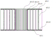
In some embodiments, the smoke eliminator 43 described with reference to fig. 4-6 comprises a smoke eliminating housing 432, a smoke eliminating device 431 mounted in the smoke eliminating housing 432, and a fourth driving motor 433, the fourth driving motor 433 driving the smoke eliminator 43 to rotate; the smoke abatement shell 432 is provided with inlets 43121 for smoke and water to flow in respectively; the inlet 43121 is respectively communicated with the smoke recovery channel and the water inlet pipeline 42, and the outlet is also arranged on the smoke abatement shell 432 and is communicated with the impeller 44; the smoke abatement device 431 comprises a bottom plate 4311 and a top plate 4312, at least two annular blade sets 4313 disposed between the bottom plate 4311 and the top plate 4312; all the annular blade groups 4313 are coaxially arranged along the axis of the bottom plate 4311, and both ends of all the annular blade groups 4313 are hermetically connected with the bottom plate 4311 and the top plate 4312; each annular blade set 4313 comprises a plurality of blades 43131 arranged in an annular array along the axis of the bottom plate 4311, and each annular blade set 4313 has a spacing between adjacent blades 43131; a liquid inlet is formed in the top plate 4312 and is in sealed connection with an inlet 43121 through a pipeline, and the inner diameter of the liquid inlet is smaller than that of the annular blade group with the smallest inner diameter; a gap is formed between the smoke abatement shell 432 and the outermost annular blade set 4313.
Preferably, the bottom plate 4311 and the top plate 4312 are coaxially disposed.
In some embodiments, the annular blade set 4313 comprises a first fixing ring 43132, a second fixing ring 43133 and a plurality of blades 43131 annularly arrayed between the first fixing ring 43132 and the second fixing ring 43133, and the plurality of blades 43131 constituting the annular blade set 4313 are connected into a whole by the first fixing ring 43132 and the second fixing ring 43133, so as to facilitate installation. Preferably, each of the blades 43131 is welded or integrally formed with the first fixing ring 43132 and the second fixing ring 43133. The annular blade set 4313 is then secured between the bottom plate 4311 and the top plate 4312 by a first securing ring 43132 and a second securing ring 43133.
In some embodiments, the first and second retaining rings 43132 and 43133 are welded or removably attached to the bottom and top plates 4311 and 4312, respectively, by bolts. Preferably, the first fixing ring 43132 and the second fixing ring 43133 are detachably connected to the bottom plate 4311 and the top plate 4312 by bolts, respectively, so as to facilitate installation, detachment, replacement, and repair and maintenance of each annular blade set 4313.
The smoke and water enter the inlet 43121 of the smoke eliminator 43 along the inlet 43121 on the smoke eliminator shell 432, so that the high-temperature smoke and water enter the middle of the smoke eliminator 43, and under the centrifugal action of the smoke eliminator 43 rotating at high speed, the smoke and water quickly and uniformly flow into the gap between the outermost annular blade set 4313 and the smoke eliminator shell 432 from the gap between the outermost annular blade set 4313 and the smoke eliminator shell 432, and then flow into the outlet from the gap between the outermost annular blade set 4313 and the smoke eliminator shell 432, and the smoke eliminator 43 is removed. When the flue gas flows rapidly in the annular blade group 4313, the flue gas is cut into a plurality of micro bubbles by a plurality of blades 43131 forming the annular blade group 4313, and similarly, water is also cut and atomized, so that the flue gas and the water can be fully contacted and mixed, dust, particles and the like in the flue gas fully absorb the water, the gas dissolved in the water is absorbed by the water, and the absorption of harmful substances in the flue gas is realized.
In some embodiments, the number of blades 43131 of the outermost annular blade set 4313 array is less than the number of blades 43131 of the remaining annular blade set 4313 arrays, which improves the smoke handling capacity of the smoke eliminator 43. Preferably, the ratio of the number of the blades 43131 of the outermost annular blade set 4313 array to the number of the blades 43131 of the remaining annular blade set 4313 array is at least 4 times higher than the smoke treatment capacity of the smoke abatement device 431.
In some embodiments, the flue gas recovery duct 413 comprises an inlet pipe 4131 and a premix elbow 4132; one end of the premixing bent pipe 4132 is connected with the air inlet pipe 4131, and the other end of the premixing bent pipe 4132 is connected with an inlet 43121 of the smoke abatement device 431; the distal end of the inlet pipe 4131 communicates with the exhaust port of the cyclone separator 412; the water inlet pipe 42 is communicated with the premixing elbow 4132, and the axis of the water inlet pipe 42 is tangent to the inner side wall of the premixing elbow 4132, so that the smoke and the water are premixed in the premixing pipe, and the absorption effect of the smoke is improved.
In some embodiments, a variable pressure valve is further disposed on the water inlet pipe 42 to increase the water inlet pressure in the water inlet pipe 42, and increase the premixing effect of the flue gas and the water through the premixing bend. Preferably, the water inlet pipe 42 includes a large-diameter pipe 421 with a larger inner diameter and a small-diameter pipe 422 with a smaller inner diameter; one end of the small-diameter pipeline 422 is connected with the large-diameter pipeline 421, the other end of the small-diameter pipeline is connected with the air inlet pipe 4131, the water inlet pressure of the water inlet pipeline 42 can be improved through the reducing pipeline, and an additional pressure regulating valve is not needed. More preferably, the ratio of the inner diameter of the large-diameter pipe 421 to the inner diameter of the small-diameter pipe 422 is at least 2: 1.
In some embodiments, referring to fig. 11 and 12, the coarse grinding device 3222 and the dehydration and degreasing device are integrated into an integrated sorting, dehydration and degreasing integrated device 2; the integrative device of separation dehydration degrease 2 includes: the device comprises a shell 23, a sorting crushing section and a dehydration degreasing section, wherein the sorting crushing section and the dehydration degreasing section are arranged in the shell 23; the sorting and crushing section comprises a rotary screen 21 and a coarse crushing device 3222 arranged in the rotary screen 21; a collecting hopper 24 is arranged below the rotary screen 21; the dehydration and degreasing section comprises a spiral squeezing device 25 and a heating device 26 for heating, the spiral squeezing device 25 is arranged below the rotary screen 21, and a material receiving port 255 hermetically connected with the material collecting hopper 24 is arranged on the spiral squeezing device 25; the shell 23 comprises a first shell 231 sleeved outside the rotary screen 21 and a second shell 232 sleeved on the conveying device, and the first shell 231 is hermetically connected with the aggregate bin 24; the second shell 232 is hermetically connected with the material receiving port 255; the second housing 232 is provided with an air outlet 2321 communicated with the flue gas recovery system 4.
Referring to fig. 13, the coarse crushing device 3222 includes a rotating shaft 221 coaxially disposed with the rotating screen 21, a plurality of crushing blades 222 uniformly disposed on the rotating shaft 221 and having a vertical axis of the rotating shaft 221, and a first driving motor 223, wherein the rotating shaft 221 is connected to an output end of the first driving motor 223.
It should be noted that the rotating screen 21 is arranged obliquely, and the higher end of the rotating screen 21 is set as a feeding end, and the lower end is set as a sorting outlet 212 end; the inner diameter of the rotary screen 21 is gradually reduced from the feeding end to the sorting outlet 212 section; the rotating screen 21 is a hollow structure provided with a plurality of through holes; the rotary screen 21 is externally connected with a second driving motor 213. The first drive motor 223 and the second drive motor 213 are commercially available reduction motors 251. The feed end of the rotating screen 21 is provided with a first feed inlet 211. The first housing 231 is mounted on a side wall of the rotary screen 21 and completely covers the side wall of the rotary screen 21; meanwhile, a gap is formed between the inner side wall of the first housing 231 and the outer side wall of the rotary screen 21, and an opening matched with the material collecting hopper 24 is arranged below the first housing 231 and is connected with the material collecting hopper 24 in a sealing manner. The first housing 231 and the hopper 24 are welded or bolted.
In some embodiments, the crushing blades 222 are spirally arranged on the rotating shaft 221, so as to improve the crushing effect of the kitchen waste.
In some embodiments, the direction of rotation of the coarse comminution means 3222 is opposite to the direction of rotation of the rotating screen 21, reducing the rate of rotation of the rotating screen 21 and the coarse comminution means 3222 and saving energy. It should be noted that the crushing blade 222 is edged on one side or both sides, and a space is provided between one end of the crushing blade 222 away from the rotating shaft 221 and the inner side wall of the rotating screen 21. The distance between the distal end of the crushing blade 222 and the inside wall of the rotating screen 21 is not too large by 5 mm.
In some embodiments, referring to fig. 17, a deodorization device 27 for deodorizing kitchen waste is further disposed at the feed end of the rotary screen 21, so that the kitchen waste is deodorized just before entering the rotary screen 21, thereby preventing odor from dissipating during the processes of dehydration, degreasing and coarse crushing of the kitchen waste and deteriorating the kitchen waste treatment environment.
The deodorizing solution is an aqueous solution prepared from a commercially available garbage deodorizing solution, for example, a deodorizing solution prepared by diluting a garbage transfer station deodorizer by 100 to 500 times.
In some embodiments, the deodorizing device 27 comprises an annular pipeline 271 arranged on the inner side surface of the feed end of the rotary screen 21 and a plurality of spray heads 272 uniformly arranged on the annular pipeline 271, and the kitchen waste is deodorized by spraying a deodorizing liquid through the spray heads 272; the annular pipeline 271 is externally connected with a water tank filled with deodorant liquid and used for providing the deodorant liquid. The injection direction of the injection head 272 is inclined toward the inside of the rotary screen 21.
Referring to fig. 14 to 16, the screw press device 25 includes a speed reduction motor 251, a conveying chamber 252, and a screw shaft 253 disposed in the conveying chamber 252, wherein the screw shaft 253 is connected to an output end of the speed reduction motor 251; the conveying chamber 252 is located below the rotary screen 21, and the conveying chamber 252 is provided with the material receiving port 255; the transmission chamber is provided with a plurality of through holes for the outflow of the squeezed grease and sewage; the heating device 26 is arranged on the inner side or the outer side of the transmission chamber and is externally connected with a power supply; the conveying chamber 252 is connected with the first discharge hole and used for discharging dehydrated and degreased kitchen waste. Adopt spiral squeezing device 25 to realize kitchen garbage's dehydration degrease to heat simultaneously, improved dehydration degrease effect, shortened kitchen garbage's sewage treatment time.
In some embodiments, the conveying bore 252 includes a spiral conveying section 2521 and a spiral press section 2522; the receiving port 255 is arranged at the spiral conveying section 2521; the spiral pressing section 2522 comprises a pressing cage 25221 sleeved on the spiral shaft 253; the shaft diameter of the spiral shaft 253 gradually increases from the material receiving port 255 to one end of the first material outlet, that is: the spiral shaft 253 comprises a central shaft and spiral blades arranged on the central shaft, the shaft diameter of the central shaft is gradually increased, and the diameters of the spiral blades are unchanged; the heating device 26 is disposed inside or outside the screw press section 2522. The heating cylinder net is arranged on the outer surface of the spiral squeezing section 2522 and used for heating the kitchen waste.
Referring to fig. 7 and 8, the pulverizing and drying mechanism includes a cylinder 31 and a fine pulverizing device 32 installed in the cylinder 31; a second feeding hole 311 and a second discharging hole 312 are respectively arranged at two ends of the cylinder 31, and an air inlet 313 is also arranged at one end of the second feeding hole 311 of the cylinder 31; the fine crushing device 32 comprises a rotating shaft 321 and a plurality of crushing blades 322 which are uniformly connected on the rotating shaft 321 and rotate along with the rotating shaft 321; the rotating shaft 321 extends along the axis of the cylinder 31, and the length of the crushing knife 322 is smaller than the distance between the rotating shaft 321 and the inner side wall of the cylinder 31; the rotating shaft 321 is connected with a third driving motor 323 for driving the rotating shaft 321 to rotate; the air outlet of the hot blast stove 33 is connected to the air inlet 313 to blow hot air into the cylinder 31.
In some embodiments, each crushing knife 322 is hinged to the rotating shaft 321, and the rotating shaft 321 rotating at a high speed drives the crushing knife 322 to rotate under the action of centrifugal force and inertia, so that the kitchen waste is crushed, and the energy consumption is saved.
The crushing blade 322 is provided with a single edge and/or double edges; the hinge of the rotating shaft 321 of the crushing knife 322 can be achieved by the following structure: referring to fig. 9, a connecting ring 3221 is disposed at one end of the crushing blade 322, a snap ring 3211 is disposed on the rotating shaft 321, and the crushing blade 322 is detachably hinged to the snap ring 3211 through the connecting ring 3221, so as to realize the hinge connection between the crushing blade 322 and the rotating shaft 321.
In some embodiments, the crushing blades 322 are spirally arranged on the rotating shaft 321, so as to improve the crushing effect; meanwhile, with the rotation of the crushing knife 322, the hot air forms a plurality of vortexes in the cylinder 31, and a better drying effect is achieved.
In some embodiments, referring to fig. 10, a hot air duct 331 for conveying hot air is arranged between the air outlet of the hot blast stove 33 and the air inlet 313, and the length of the hot air duct 331 is at least 3 m. The hot blast stove 33 mostly uses fuel to burn and heat air to form hot air, so that most of air outlets of the hot blast stove 33 are provided with fire tongues, and the hot blast stove is in direct contact with the kitchen waste to cause carbonization and coking of the kitchen waste. A hot air pipeline 331 is arranged between an air outlet and an air inlet 313 of the hot blast stove 33, so that a firebrick in the hot blast stove 33 is prevented from entering the barrel body 31, and coking of kitchen waste is reduced.
In some embodiments, said air inlet 313 is provided in plurality, and a plurality of said air inlets 313 are annularly arrayed along the axis of said cylinder 31; hot-air pipe 331 with be provided with between the air inlet 313 with the annular gas distribution pipe 34 of hot-air pipe 331 intercommunication, annular gas distribution pipe 34 passes through branch pipe and each air inlet 313 intercommunication makes in hot-air gets into barrel 31 from a plurality of air inlets 313, makes in the even entering barrel 31 of hot-air, kitchen garbage is heated evenly.
In some embodiments, a screw feeder is connected between the first discharge hole and the second discharge hole 311, and the dehydrated and degreased kitchen waste discharged from the first discharge hole is fed into the second discharge hole 311 through the screw feeder, so that manual operation is reduced.
In some embodiments, the screw feeder is further provided with a chemical adding device at an end close to the first feeding hole 211. The agent adding device directly adds additives to be added, such as a coking inhibitor, an oxygenating agent and the like, into the dehydrated and degreased kitchen waste in the screw feeder, and then the additives are transmitted through the screw feeder and uniformly mixed with the dehydrated and degreased kitchen waste without additionally arranging a stirrer.
It should be noted that, in the above technical solution, the cylinder 31 is horizontally arranged or slightly inclined towards the discharge port, and the temperature of the hot air provided by the hot-air furnace 33 is at least 1000 ℃, so as to realize high-temperature drying of the kitchen waste. The third driving motor 323 may be a commercially available motor or a reduction motor 251.
In some embodiments, each crushing knife 322 is hinged to the rotating shaft 321, and the rotating shaft 321 rotating at a high speed drives the crushing knife 322 to rotate under the action of centrifugal force and inertia, so that the kitchen waste is crushed, and the energy consumption is saved.
The crushing blade 322 is provided with a single edge and/or double edges; the hinge of the rotating shaft 321 of the crushing knife 322 can be achieved by the following structure:
one end of the crushing knife 322 is provided with a connecting ring 3221, the rotating shaft 321 is provided with a snap ring 3211, and the crushing knife 322 is detachably hinged with the snap ring 3211 through the connecting ring 3221, so that the crushing knife 322 is hinged with the rotating shaft 321.
In some embodiments, the crushing blades 322 are spirally arranged on the rotating shaft 321, so as to improve the crushing effect; meanwhile, with the rotation of the crushing knife 322, the hot air forms a plurality of vortexes in the cylinder 31, and a better drying effect is achieved.
In some embodiments, the length of the crushing blade 322 is 1-5 mm less than the distance from the rotating shaft 321 to the inner side wall of the cylinder 31.
In some embodiments, a hot air duct 331 for transporting hot air is arranged between the air outlet of the hot blast stove 33 and the air inlet 313, and the length of the hot air duct 331 is at least 3 m. The hot blast stove 33 mostly uses fuel to burn and heat air to form hot air, so that most of air outlets of the hot blast stove 33 are provided with fire tongues, and the hot blast stove is in direct contact with the kitchen waste to cause carbonization and coking of the kitchen waste. A hot air pipeline 331 is arranged between an air outlet and an air inlet 313 of the hot blast stove 33, so that a firebrick in the hot blast stove 33 is prevented from entering the barrel body 31, and coking of kitchen waste is reduced.
In some embodiments, said air inlet 313 is provided in plurality, and a plurality of said air inlets 313 are annularly arrayed along the axis of said cylinder 31; hot-air pipe 331 with be provided with between the air inlet 313 with the annular gas distribution pipe 34 of hot-air pipe 331 intercommunication, annular gas distribution pipe 34 passes through branch pipe and each air inlet 313 intercommunication makes in hot-air gets into barrel 31 from a plurality of air inlets 313, makes in the even entering barrel 31 of hot-air, kitchen garbage is heated evenly.
When the kitchen waste treatment device is used, kitchen waste to be treated is firstly accumulated in the bin 1, continuously flowing hot water is introduced into the inner surface of the bin 1, so that the kitchen waste in the bin 1 is preheated, the preheated kitchen waste is put into the integrated sorting, dewatering and degreasing integrated device 2 from the first feeding hole 211, and deodorant solution is sprayed when the kitchen waste passes through the feeding end of the rotary screen 21, so that the odor of the kitchen waste is removed; then, the breakable solid waste in the kitchen waste is broken into coarse particles with the particle size not larger than 1cm by the breaking knife 222, and the flexible plastic which is not easy to break, such as preservative film, is discharged through the sorting outlet 212 and is recycled; the crushed kitchen waste coarse particles enter the spiral squeezing device 25 through the collecting hopper 24 and the material receiving port 255, are conveyed to the spiral squeezing section 2522 along the conveying chamber 252 through the spiral shaft 253, and are heated and squeezed, so that grease and sewage in the kitchen waste are squeezed and removed, and the dehydrated and degreased kitchen waste coarse particles are obtained. Feeding the dehydrated and degreased kitchen waste coarse particles into a spiral feeder, adding a coking inhibitor and an oxygenation agent through a dosing device, feeding the uniformly mixed kitchen waste coarse particles, coking inhibitor and oxygenation agent into a crushing and drying mechanism from a second feeding hole 311, and crushing the kitchen waste coarse particles into kitchen waste fine particles with the particle size not more than 1mm through a fast-rotating crushing knife 222; meanwhile, hot air with the temperature higher than 1000 ℃ is blown into the cylinder 31 by the hot blast stove 33, the kitchen waste fine particles are quickly dried and blown out to the second discharge port 312 along with the hot air to enter the ascending pipeline 411. In the ascending pipe 411, the wind speed and the pressure of the hot air are reduced, the kitchen waste particles are continuously dried into powder fuel, and the powder fuel enters the cyclone separator 412 for gas-solid separation, so that the powder fuel is separated; the separated high-temperature flue gas enters the smoke eliminator 43 through an air return pipeline, is fully mixed with water and then is introduced into the liquid collecting tank through the impeller 44, so that the high-temperature flue gas is absorbed. And the water in the liquid collecting tank absorbs the high-temperature flue gas, then the temperature is raised, and then the water is introduced into a preheating pipeline of the storage bin 1 to preheat the kitchen waste to be treated.
The preferred embodiments of the present invention have been described in detail, however, the present invention is not limited to the specific details of the above embodiments, and various simple modifications may be made to the technical solution of the present invention within the technical idea of the present invention, and these simple modifications are within the protective scope of the present invention.
The above description is only for the purpose of illustrating the preferred embodiments of the present invention and is not to be construed as limiting the utility model, and any modifications, equivalents and improvements made within the spirit and principle of the present invention are intended to be included within the scope of the present invention.
Claims (10)
1. A production line for preparing solid fuel by kitchen waste is characterized by comprising a storage bin, a coarse crushing device, a dehydration and degreasing device and a high-temperature crushing and drying device which are sequentially connected;
the high-temperature crushing and drying device comprises a hot blast stove and a crushing and drying mechanism, and an air outlet of the hot blast stove is communicated with the crushing and drying mechanism;
the air outlet of the crushing and drying mechanism is communicated with the storage bin through a flue gas recovery system.
2. The production line for preparing the solid fuel by the kitchen waste as claimed in claim 1, wherein the bin comprises a bin body and a spiral or S-shaped preheating channel arranged on the inner side wall of the bin body, and the flue gas recovery system is communicated with the preheating channel.
3. The production line for preparing the solid fuel by the kitchen waste as claimed in claim 2, wherein the flue gas recovery system comprises a return air channel, a water inlet pipeline, a smoke eliminator, an impeller and a water collecting tank;
one end of the air return channel is communicated with an air outlet of the crushing and drying mechanism, the other end of the air return channel is connected with the smoke eliminator, and the water inlet pipeline is communicated with the smoke eliminator; the impeller is arranged in the water collecting tank and is communicated with the outlet of the smoke eliminator;
the water collecting tank is provided with a liquid supply pipeline communicated with the preheating channel.
4. The production line for preparing the solid fuel by the kitchen waste as claimed in claim 3, wherein the return air channel comprises an ascending pipeline, a cyclone separator and a flue gas recovery pipeline which are connected in sequence; one end of the ascending pipeline is connected with an air outlet of the crushing and drying mechanism, and the other end of the ascending pipeline is connected with a fluid inlet of the cyclone separator; one end of the smoke recovery channel is connected with the exhaust port of the cyclone separator, and the other end of the smoke recovery channel is connected with the smoke eliminator.
5. The production line for preparing the solid fuel by the kitchen waste as claimed in claim 4, wherein the ascending pipe is of a funnel-shaped structure with a large upper part and a small lower part.
6. The production line for preparing the solid fuel by the kitchen waste as claimed in claim 5, wherein the smoke eliminator comprises a smoke eliminating housing, a smoke eliminating device mounted in the smoke eliminating housing and a fourth driving motor, and the fourth driving motor drives the smoke eliminating device to rotate; the smoke abatement shell is provided with an inlet for smoke and water to flow in; the inlet is communicated with the smoke recovery channel and the water inlet pipeline, and the outlet is also arranged on the smoke abatement shell and communicated with the impeller;
the smoke abatement device comprises a bottom plate, a top plate and at least two annular blade sets arranged between the bottom plate and the top plate; all the annular blade sets are coaxially arranged along the axis of the bottom plate, and two ends of all the annular blade sets are hermetically connected with the bottom plate and the top plate;
each annular blade group comprises a plurality of blades which are arrayed annularly along the axis of the bottom plate;
the top plate is provided with a liquid inlet, the liquid inlet is in sealing connection with an inlet through a pipeline, and the inner diameter of the liquid inlet is smaller than that of the annular blade group with the minimum inner diameter;
and a gap is formed between the smoke abatement shell and the annular blade group on the outermost side.
7. The production line for preparing the solid fuel by the kitchen waste according to claim 1, wherein the coarse crushing device and the dehydration and degreasing device are integrated into an integrated sorting, dehydration and degreasing integrated device;
integrative device of separation dehydration degrease of integration includes: the device comprises a shell, a sorting and crushing section and a dehydration and degreasing section, wherein the sorting and crushing section and the dehydration and degreasing section are arranged in the shell;
the sorting and crushing section comprises a rotary screen and a coarse crushing device arranged in the rotary screen; a collecting hopper is arranged below the rotary screen;
the dehydration and degreasing section comprises a spiral squeezing device and a heating device for heating, the spiral squeezing device is arranged below the rotary screen, and a material receiving port hermetically connected with a material collecting hopper is arranged on the spiral squeezing device;
the shell comprises a first shell sleeved outside the rotary screen and a second shell sleeved on the conveying device, and the first shell is connected with the aggregate bin in a sealing manner; the second shell is hermetically connected with the material receiving port; and the second shell is provided with an air outlet communicated with the flue gas recovery system.
8. The production line for preparing the solid fuel by the kitchen waste according to claim 7, wherein the screw pressing device comprises a speed reduction motor, a conveying chamber and a screw shaft arranged in the conveying chamber, and the screw shaft is connected with an output end of the speed reduction motor;
the conveying chamber is positioned below the rotary screen and is provided with the material receiving port;
the conveying chamber is provided with a plurality of through holes; the heating device is arranged on the inner side or the outer side of the transmission chamber; the one end that connects the material mouth is kept away from to the conveying thorax is provided with first discharge gate.
9. The production line for preparing the solid fuel by the kitchen waste according to claim 1, wherein the crushing and drying mechanism comprises a barrel body and a fine crushing device arranged in the barrel body;
a second feeding hole and a second discharging hole are respectively formed in the two ends of the cylinder body, and an air inlet is further formed in one end of the second feeding hole of the cylinder body;
the fine crushing device comprises a rotating shaft and a plurality of crushing knives which are uniformly connected to the rotating shaft and rotate along with the rotating shaft; the rotating shaft extends along the axis of the cylinder, and the length of the crushing knife is smaller than the distance between the rotating shaft and the inner side wall of the cylinder; the rotating shaft is connected with a driving motor for driving the rotating shaft to rotate;
and an air outlet of the hot blast stove is connected with the air inlet and blows hot air into the cylinder.
10. The production line for preparing the solid fuel by the kitchen waste according to claim 9, wherein a screw feeder is connected to the second feeding hole, and a chemical adding device is arranged at one end, far away from the second feeding hole, of the screw feeder.
Priority Applications (1)
| Application Number | Priority Date | Filing Date | Title |
|---|---|---|---|
| CN202120357484.0U CN215712855U (en) | 2021-02-07 | 2021-02-07 | Production line for preparing solid fuel from kitchen waste |
Applications Claiming Priority (1)
| Application Number | Priority Date | Filing Date | Title |
|---|---|---|---|
| CN202120357484.0U CN215712855U (en) | 2021-02-07 | 2021-02-07 | Production line for preparing solid fuel from kitchen waste |
Publications (1)
| Publication Number | Publication Date |
|---|---|
| CN215712855U true CN215712855U (en) | 2022-02-01 |
Family
ID=80012287
Family Applications (1)
| Application Number | Title | Priority Date | Filing Date |
|---|---|---|---|
| CN202120357484.0U Active CN215712855U (en) | 2021-02-07 | 2021-02-07 | Production line for preparing solid fuel from kitchen waste |
Country Status (1)
| Country | Link |
|---|---|
| CN (1) | CN215712855U (en) |
-
2021
- 2021-02-07 CN CN202120357484.0U patent/CN215712855U/en active Active
Similar Documents
| Publication | Publication Date | Title |
|---|---|---|
| CN111853802A (en) | Garbage drying and pyrolyzing method | |
| CN106369937B (en) | A kind of coal slime drying system and its drying process | |
| KR101729994B1 (en) | Low-temperature dry apparatus for sludge using heat transfer media and dry method thereof | |
| KR102191214B1 (en) | Drying apparatus | |
| CN206191603U (en) | Novel environment is useless processing admittedly device | |
| CN208303479U (en) | Utilize ultrasound-enhanced organic waste pyrolytic gasification equipment | |
| KR200349559Y1 (en) | Food wastes treatment machine | |
| CN215712855U (en) | Production line for preparing solid fuel from kitchen waste | |
| CN205701818U (en) | Food waste treatment device | |
| CN101900479B (en) | Poultry excrement drying device | |
| CN205115263U (en) | Utilize sludge drying equipment of low temperature flue gas | |
| CN212538463U (en) | Air-flowing type crushing and drying device | |
| CN108793668B (en) | Method for atomizing, drying and incinerating sludge | |
| CN112795417A (en) | Production line for preparing solid fuel from kitchen waste | |
| CN206385112U (en) | The system that sludge dehydrating and drying prepares garbage derivatived fuel | |
| CN203657372U (en) | Vertical rapid kitchen waste drying device | |
| CN202792077U (en) | Biomass feeding device integrating sieving and drying and conveying | |
| CN206318859U (en) | A kind of industrial sludge decrement treatment system | |
| CN110108092B (en) | High-speed rotational flow low-temperature drying system, method and application | |
| CN106635237A (en) | System and technology for preparing garbage derivative fuel by dewatering and drying sludge | |
| CN210663595U (en) | Flash drying device of environmental protection | |
| CN108515638A (en) | A kind of technics of reclaim of plastic waste reuse method | |
| CN111397334B (en) | System and method for biomass fuel production | |
| CN213295248U (en) | Be used for saw-dust carbonization ejection of compact conveyor | |
| CN201724537U (en) | Poultry litter stirring and smashing mechanism |
Legal Events
| Date | Code | Title | Description |
|---|---|---|---|
| GR01 | Patent grant | ||
| GR01 | Patent grant |