CN215478398U - Device for automatically conveying and dumping articles in container - Google Patents
Device for automatically conveying and dumping articles in container Download PDFInfo
- Publication number
- CN215478398U CN215478398U CN202023270495.XU CN202023270495U CN215478398U CN 215478398 U CN215478398 U CN 215478398U CN 202023270495 U CN202023270495 U CN 202023270495U CN 215478398 U CN215478398 U CN 215478398U
- Authority
- CN
- China
- Prior art keywords
- frame
- chain wheel
- storage hopper
- connecting frame
- frame body
- Prior art date
- Legal status (The legal status is an assumption and is not a legal conclusion. Google has not performed a legal analysis and makes no representation as to the accuracy of the status listed.)
- Active
Links
Images


Landscapes
- Filling Or Emptying Of Bunkers, Hoppers, And Tanks (AREA)
Abstract
The utility model provides a device for automatically conveying and dumping articles in a container, which comprises: the device comprises a frame body, a lifting mechanism arranged in the middle of the frame body, and a storage hopper connected with the rear end of the frame body; the left end and the right end of the frame body are both provided with guide rails, the guide rails use two sections of pulley grooves which are vertical to each other, and the two sections of pulley grooves are in arc transition; the lifting mechanism adopts the matching of a motor and a chain, the transmission is stable and rapid, and the lifting force is large; the guide rail is matched with the first connecting frame and the second connecting frame, so that the dumping action is stable.
Description
Technical Field
The utility model relates to the field of material transportation, in particular to a device for automatically conveying and dumping articles contained in a container.
Background
At present, mechanization and automation are gradually realized in industrial production, and as a transport tool essential for industrial transportation, the existing tipping bucket transport vehicle taking fuel oil as power has the defects of complex structure, difficult maintenance, large occupied area and difficult dumping in a narrow workshop although the carrying capacity is large.
SUMMERY OF THE UTILITY MODEL
The utility model provides a device for automatically conveying and dumping articles contained in a container, aiming at solving the problems in the prior art.
An apparatus for automatically transferring contents of a pouring container, comprising: the device comprises a frame body, a lifting mechanism arranged in the middle of the frame body and a storage hopper connected with the rear end of the frame body.
Furthermore, in order to enable the materials to be stably poured, a storage hopper frame is further arranged at the lower end of the storage hopper, a first connecting frame is arranged at the front end of the storage hopper and connected with the storage hopper frame, and the first connecting frame is connected with a second connecting frame through a pin shaft.
Further, in order to make the lift steady, adopt chain drive, elevating system includes: the chain wheel assembly comprises a motor, a motor seat, a first chain wheel, a second chain wheel and a chain, wherein the motor seat is positioned at the front end of a frame body and connected with the motor, the first chain wheel is arranged on an output shaft of the motor, the second chain wheel is arranged on the chain wheel seat and the chain is assembled on the first chain wheel and the second chain wheel.
Furthermore, in order to enable the materials to rise to the dumping position, pulleys are arranged on the first connecting frame and the second connecting frame, the pulleys are embedded in the guide rails, and a connecting device is arranged in the middle of the second connecting frame and connected with the chain.
Furthermore, in order to facilitate material transportation, the bottom end of the frame body is provided with rollers.
The utility model has the technical effects that: both ends all are equipped with the guide rail about the support body, and the guide rail uses two sections mutually perpendicular's pulley grooves, passes through the circular arc transition between two sections pulley grooves, leads the removal of storage hopper, and the material passes through link one and link two and guide rail cooperation, can make the storage hopper accomplish promote with the 90 fortune material of upset action of empting, and elevating system has adopted chain drive, goes up and down more steadily to whole device is installed on the support body that can remove in a flexible way, and the propelling movement of being convenient for is used to each application place.
Drawings
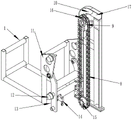
FIG. 1 is an isometric view of a transport device of the present invention;
FIG. 2 is a schematic view of the cooperative connection of the hopper frame, the connecting frame and the guide rail according to the present invention;
FIG. 3 is a front view of the guide rail of the present invention;
in the figure, 1, a storage hopper frame, 2, a storage hopper, 3, rollers, 4, a frame body, 5, a motor base, 6, a lifting mechanism, 7, a motor, 8, a chain, 9, a chain wheel base, 10, a guide rail, 11, a first connecting frame, 12, a pulley, 13, a second connecting frame, 14, a connecting device, 15, a first chain wheel, 16, a second chain wheel, 17, a vertical linear groove, 18, a quarter arc groove and 19, a horizontal linear groove are arranged.
Detailed Description
The following describes an embodiment of the present invention with reference to fig. 1 to 3.
Fig. 1 illustrates an overall structure of an apparatus for automatically transferring contents in a pouring container, comprising: the device comprises a frame body 4, a lifting mechanism 6 arranged in the middle of the frame body 4, and a storage hopper 2 connected with the rear end of the frame body 4; the left end and the right end of the frame body 4 are both provided with a guide rail 10; the lifting mechanism 6 includes: the chain wheel mechanism comprises a motor 7, a motor base 5, a first chain wheel 15, a chain wheel base 9, a second chain wheel 16 and a chain 8, wherein the motor base 5 is positioned at the front end of a frame body 4 and connected with the motor 7, the chain wheel 15 is arranged on an output shaft of the motor 7, the chain wheel base 9 is arranged at the upper end of the frame body 4, the chain wheel 16 is arranged on the chain wheel base 9, and the chain 8 is assembled on the chain wheel 15 and the chain wheel 16; the bottom end of the frame body 4 is provided with a roller 3.
FIG. 2 shows a storage hopper frame, a connecting frame and a guide rail of the device for automatically conveying and dumping articles in a container are matched and connected, the lower end of a storage hopper 2 is also provided with the storage hopper frame 1, the front end of the storage hopper 2 is provided with a first connecting frame 11, the first connecting frame 11 is connected with the storage hopper frame 1, and the first connecting frame 11 is connected with a second connecting frame 13 through a pin shaft; the first connecting frame 11 and the second connecting frame 13 are both provided with pulleys 12, the pulleys 12 are embedded in the guide rails 10, the middle of the second connecting frame 13 is also provided with a connecting device 14, and the connecting device 14 is connected with the chain 8.
Fig. 3 illustrates a guide rail structure of an apparatus for automatically transferring contents in a pouring container, the guide rail comprising: the vertical straight line groove 17, the quarter arc groove 18 connected with the upper end of the vertical straight line groove 17, and the horizontal straight line groove 19 connected with one end connected with the vertical straight line groove 17 are far away from the quarter arc groove 18.
The working principle is as follows: the material dress is in storage hopper 2, storage hopper 2 is put on storage hopper frame 1, with the device propelling movement to the position that needs topple over, starter motor 7, motor 7 output shaft drives sprocket 15 and rotates, sprocket 15 drives sprocket two 16 through chain 8 and rotates, link two 13 rise to along with chain 8 through connecting device 14, because the restriction of guide rail 10, link one 11 and link two 13 drive storage hopper 2 and accomplish to rise, topple over the action, treat that the material topples over the back that finishes, starter motor 7 reversal, storage hopper 2 gets back to on the initial position, continue the transportation next time.
Finally, it should be noted that: the above examples are only intended to illustrate the technical solution of the present invention, but not to limit it; although the present invention has been described in detail with reference to the foregoing embodiments, it will be understood by those of ordinary skill in the art that: the technical solutions described in the foregoing embodiments may still be modified, or some or all of the technical features may be equivalently replaced; and the modifications or the substitutions do not make the essence of the corresponding technical solutions depart from the scope of the technical solutions of the embodiments of the present invention.
Claims (5)
1. An apparatus for automatically transferring contents of a pouring container, comprising: the device comprises a frame body (4), a lifting mechanism (6) arranged in the middle of the frame body (4), and a storage hopper (2) connected with the rear end of the frame body (4);
the method is characterized in that: guide rails (10) are arranged at the left end and the right end of the frame body (4), two sections of mutually vertical pulley grooves (17) are used for the guide rails, and the two sections of pulley grooves (17) are in arc transition.
2. The device for automatically conveying and dumping the contents of a container according to claim 1, wherein the lower end of the storage hopper (2) is further provided with a first storage hopper frame (1), the front end of the storage hopper (2) is provided with a first connecting frame (11), the first connecting frame (11) is connected with the first storage hopper frame (1), and the first connecting frame (11) is connected with a second connecting frame (13) through a pin shaft.
3. An apparatus for automatically transferring contents of a pouring container according to claim 2, wherein said lifting mechanism (6) comprises: the chain wheel assembly comprises a motor (7), a motor base (5) located at the front end of a rack body (4) and connected with the motor (7), a first chain wheel (15) on an output shaft of the motor (7), a chain wheel base (9) at the upper end of the rack body (4), a second chain wheel (16) on the chain wheel base (9), and a chain (8) assembled on the first chain wheel (15) and the second chain wheel (16).
4. An automatic conveying and pouring device for the contents of containers, as in claim 3, characterized in that said first connecting frame (11) and said second connecting frame (13) are provided with pulleys (12), the pulleys (12) being embedded in the guide rails (10), and in that a connecting device (14) is provided between the second connecting frame (13), the connecting device (14) being connected to the chain (8).
5. An automatic transfer and pouring device for contents of containers, as in claim 1, characterized in that the lower end of said frame (4) is provided with rollers (3).
Priority Applications (1)
| Application Number | Priority Date | Filing Date | Title |
|---|---|---|---|
| CN202023270495.XU CN215478398U (en) | 2020-12-30 | 2020-12-30 | Device for automatically conveying and dumping articles in container |
Applications Claiming Priority (1)
| Application Number | Priority Date | Filing Date | Title |
|---|---|---|---|
| CN202023270495.XU CN215478398U (en) | 2020-12-30 | 2020-12-30 | Device for automatically conveying and dumping articles in container |
Publications (1)
| Publication Number | Publication Date |
|---|---|
| CN215478398U true CN215478398U (en) | 2022-01-11 |
Family
ID=79718017
Family Applications (1)
| Application Number | Title | Priority Date | Filing Date |
|---|---|---|---|
| CN202023270495.XU Active CN215478398U (en) | 2020-12-30 | 2020-12-30 | Device for automatically conveying and dumping articles in container |
Country Status (1)
| Country | Link |
|---|---|
| CN (1) | CN215478398U (en) |
Cited By (1)
| Publication number | Priority date | Publication date | Assignee | Title |
|---|---|---|---|---|
| CN114803356A (en) * | 2022-05-17 | 2022-07-29 | 江苏宏芯亿泰智能装备有限公司 | Lifting material pouring device |
-
2020
- 2020-12-30 CN CN202023270495.XU patent/CN215478398U/en active Active
Cited By (2)
| Publication number | Priority date | Publication date | Assignee | Title |
|---|---|---|---|---|
| CN114803356A (en) * | 2022-05-17 | 2022-07-29 | 江苏宏芯亿泰智能装备有限公司 | Lifting material pouring device |
| CN114803356B (en) * | 2022-05-17 | 2024-03-01 | 江苏宏芯亿泰智能装备有限公司 | Lifting and pouring device |
Similar Documents
| Publication | Publication Date | Title |
|---|---|---|
| CN200961059Y (en) | Transporting and loading device | |
| CN215478398U (en) | Device for automatically conveying and dumping articles in container | |
| CN109823810A (en) | A kind of novel energy-storing vanadium cell pile production conveying device | |
| CN105947614A (en) | Equipment convenient to acquire supervision code for turning over whole box of medicines | |
| CN204872632U (en) | Steel pipe translation device | |
| CN207748382U (en) | Battery transport system for electric charging station | |
| CN216661545U (en) | Embrace case upset and carry machine of carrying | |
| CN211035028U (en) | Material sorting single-arm elevator | |
| CN218490603U (en) | Movable belt material receiving platform | |
| CN114955429A (en) | Overhead production line material conveying equipment | |
| CN215247836U (en) | Reversing mechanism | |
| CN215363615U (en) | Transverse moving device of conveying line | |
| CN211545103U (en) | Lifting device and transfer equipment | |
| CN114348530A (en) | Fuel cell mould transfer device | |
| CN114054731A (en) | Stokehold lifting transfer trolley for molten metal transfer | |
| CN209872221U (en) | Lifting device capable of automatically conveying, storing and taking | |
| CN113213375A (en) | Movable promotes feeding device | |
| CN111846835A (en) | Hand-push type conveying elevator | |
| CN211846447U (en) | Transitional unloading platform | |
| CN212863279U (en) | Bulk grain warehousing and distributing conveyor | |
| CN212686724U (en) | Jacking conveyor | |
| CN217076082U (en) | Lifting butt joint roller way for hot galvanizing production loop line | |
| CN212952991U (en) | Clamping lifting mechanism used in charging tray feeding system | |
| CN213505815U (en) | Electric forklift with stable operation | |
| CN217263062U (en) | Positioning and conveying mechanism for battery plastic shell |
Legal Events
| Date | Code | Title | Description |
|---|---|---|---|
| GR01 | Patent grant | ||
| GR01 | Patent grant |