CN215316035U - Automatic pipe cutting machine - Google Patents
Automatic pipe cutting machine Download PDFInfo
- Publication number
- CN215316035U CN215316035U CN202121599696.6U CN202121599696U CN215316035U CN 215316035 U CN215316035 U CN 215316035U CN 202121599696 U CN202121599696 U CN 202121599696U CN 215316035 U CN215316035 U CN 215316035U
- Authority
- CN
- China
- Prior art keywords
- cutting
- cutter
- module
- pressing
- cylinder
- Prior art date
- Legal status (The legal status is an assumption and is not a legal conclusion. Google has not performed a legal analysis and makes no representation as to the accuracy of the status listed.)
- Active
Links
Images

Landscapes
- Sawing (AREA)
Abstract
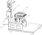
The utility model relates to the technical field of pipe fitting processing, and discloses an automatic pipe cutting machine which comprises a feeding module, a cutting module and a receiving bin, wherein the feeding module is arranged on the feeding module; the device also comprises a pre-pressing module; the prepressing module comprises a prepressing bracket and a pressing roller; a floating groove is vertically arranged on the prepressing bracket; an upper cover plate is arranged at the upper part of the pre-pressing bracket; two ends of a shaft of the compression roller extend out and then are inserted into the floating groove; the pre-pressing module further comprises a pre-pressing spring; one end of the prepressing spring is connected with the shaft of the compression roller, and the other end of the prepressing spring is connected with the upper cover plate; the feeding module comprises a sliding table cylinder and a clamping jaw cylinder; the sliding table cylinder drives the clamping jaw cylinder to reciprocate along the horizontal direction; the cutting-off module comprises a cutting-off cylinder and a cutter; the cutter is arranged on a telescopic piston rod of the cutting cylinder. The pipe cutting machine fixes the pipe, realizes cutting through the linear motion of the cutter, and has simple structure and high processing efficiency.
Description
Technical Field
The utility model relates to a pipe fitting machining device, in particular to an automatic pipe cutting machine.
Background
Tubular workpieces often need to be cut into specified lengths during processing, and in order to guarantee cutting precision and efficiency, pipe cutting equipment is mostly adopted to replace manual cutting in actual production. The existing pipe cutting machine has the setting functions of fixed-length cutting, unit production and shift production, and mostly adopts the mode of cutter rotation or pipe rotation to cut, so that the cutting requirements of most pipe fittings can be met, but the pipe with small hardness does not need complicated cutter rotation or pipe rotation action during processing, and the existing pipe cutting equipment for the pipe fittings can cause resource waste to a certain extent.
Disclosure of Invention
The utility model solves the technical problem of providing an automatic pipe cutting machine, which fixes a pipe, realizes cutting through the linear motion of a cutter, and has simple structure and high processing efficiency.
The technical scheme adopted by the utility model for solving the technical problems is as follows: an automatic pipe cutting machine comprises a feeding module, a cutting module and a receiving bin; the device also comprises a pre-pressing module; the prepressing module comprises a prepressing bracket and a pressing roller; a floating groove is vertically arranged on the prepressing bracket; an upper cover plate is arranged at the upper part of the pre-pressing bracket; two ends of a shaft of the compression roller extend out and then are inserted into the floating groove; the pre-pressing module further comprises a pre-pressing spring; one end of the prepressing spring is connected with the shaft of the compression roller, and the other end of the prepressing spring is connected with the upper cover plate; the feeding module comprises a sliding table cylinder and a clamping jaw cylinder; the sliding table cylinder drives the clamping jaw cylinder to reciprocate along the horizontal direction; the cutting-off module comprises a cutting-off cylinder and a cutter; the cutter is arranged on a telescopic piston rod of the cutting cylinder.
Further, the method comprises the following steps: the cutting module comprises a cutting bracket; the cutting cylinder is arranged on the cutting bracket; the cutter is arranged on the cutter fixing plate; the cutter fixing plate is connected with a telescopic piston rod of the cutting cylinder.
Further, the method comprises the following steps: a slide rail is vertically arranged on the cutting bracket; the cutter fixing plate is arranged on the sliding rail through a sliding block.
Further, the method comprises the following steps: the knife edge of the cutter is not horizontal.
Further, the method comprises the following steps: and a cushion block is arranged below the compression roller.
Further, the method comprises the following steps: and the clamping jaw cylinder is provided with a profiling clamping jaw matched with the pipe fitting.
The utility model has the beneficial effects that: the pipe is pressed by the compression roller of the pre-pressing module, so that the pipe is prevented from displacing due to uneven stress in the cutting process, and the subsequent cutting precision is prevented from being influenced; after the pipe is clamped by the profiling clamping jaw, the pipe is conveyed to a cutting position by the sliding table cylinder, the feeding step pitch is stable, the reliability is high, the precision maintenance is good, and the maintenance is convenient; when the pipe is cut, the cutter is driven by the cylinder to do linear motion to cut the pipe, the cutting action is rapid and efficient, and the whole operation cost of the equipment is low.
Drawings
FIG. 1 is a schematic diagram of an automatic pipe cutter;
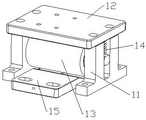
FIG. 2 is a schematic view of a pre-pressing module;
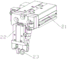
FIG. 3 is a schematic view of a feeding module;
FIG. 4 is a schematic diagram of a cutting module.
Labeled as: 1. a pre-pressing module; 11. pre-pressing the bracket; 12. an upper cover plate; 13. a compression roller; 14. pre-pressing a spring; 15. cushion blocks; 2. a feeding module; 21. a sliding table cylinder; 22. a clamping jaw cylinder; 23. profiling clamping jaws; 3. cutting off the module; 31. cutting off the bracket; 32. cutting off the air cylinder; 33. a cutter fixing plate; 34. a cutter; 35. a slide rail; 4. a material receiving bin.
Detailed Description
For the purpose of enhancing the understanding of the present invention, the present invention will be described in further detail with reference to the accompanying drawings and examples, which are provided for the purpose of illustration only and are not intended to limit the scope of the present invention.
Examples
As shown in fig. 1 to 4, an automatic pipe cutting machine includes a feeding module 2, a cutting module 3 and a receiving bin 4; the device also comprises a pre-pressing module 1; the pre-pressing module 1 comprises a pre-pressing bracket 11 and a pressing roller 13; a floating groove is vertically arranged on the pre-pressing support 11; an upper cover plate 12 is arranged at the upper part of the pre-pressing bracket 11; two ends of the shaft of the compression roller 13 extend out and then are inserted into the floating groove; the pre-pressing module 1 further comprises a pre-pressing spring 14; one end of the pre-pressing spring 14 is connected with the shaft of the compression roller 13, and the other end of the pre-pressing spring is connected with the upper cover plate 12; the feeding module 2 comprises a sliding table cylinder 21 and a clamping jaw cylinder 22; the sliding table cylinder 21 drives the clamping jaw cylinder 22 to reciprocate along the horizontal direction; the cutting module 3 comprises a cutting cylinder 32 and a cutter 34; the cutter 34 is disposed on a telescopic piston rod of the cutting cylinder 32.
On the basis of the above, the cutting module 3 includes a cutting bracket 31; the cutting cylinder 32 is mounted on the cutting bracket 31; the cutter 34 is arranged on the cutter fixing plate 33; the cutter fixing plate 33 is connected with a telescopic piston rod of the cutting cylinder 32.
On the basis, a slide rail 35 is vertically arranged on the cutting bracket 31; the cutter fixing plate 33 is mounted on the slide rail 35 through a slide block.
On the basis of the above, the edge of the cutter 34 is not horizontal.
On the basis of the above, a cushion block 15 is arranged below the press roll 13.
On the basis, the clamping jaw cylinder 22 is provided with a profiling clamping jaw 23 matched with the pipe fitting.
In practical use, a pipe is pressed between the pressing roller 13 and the cushion block 15, the clamping jaw cylinder 22 drives the profiling clamping jaw 23 to clamp the pipe, the sliding table cylinder 21 extends out to pull the pipe to the position below the cutter 34, the cutting cylinder 32 drives the cutter 34 to descend to cut off the pipe, and the cut pipe falls into the collecting bin 4 and slides out along the collecting bin 4; the slide block and the slide rail 35 can stabilize the lifting action of the cutter fixing plate 33, and prevent the cutter 34 from unsmooth operation to influence the cutting quality. The profiling clamping jaw 23 clamps the pipe fitting in the cutting process, so that the pipe fitting is prevented from moving, and the cutting quality is ensured. After cutting, the cutting cylinder 32 drives the cutter 34 to ascend, the profiling clamping jaw 23 loosens the pipe fitting, the sliding table cylinder 21 resets, and the actions are repeated to realize automatic feeding and cutting.
The above embodiments should not limit the present invention in any way, and all technical solutions obtained by using equivalent alternatives or equivalent transformations fall within the protection scope of the present invention.
Claims (6)
1. An automatic pipe cutting machine comprises a feeding module (2), a cutting module (3) and a receiving bin (4); the method is characterized in that: the device also comprises a prepressing module (1); the pre-pressing module (1) comprises a pre-pressing bracket (11) and a pressing roller (13); a floating groove is vertically arranged on the pre-pressing support (11); an upper cover plate (12) is arranged at the upper part of the pre-pressing bracket (11); two ends of a shaft of the compression roller (13) extend out and then are inserted into the floating groove; the pre-pressing module (1) further comprises a pre-pressing spring (14); one end of the pre-pressing spring (14) is connected with a shaft of the press roller (13), and the other end of the pre-pressing spring is connected with the upper cover plate (12); the feeding module (2) comprises a sliding table cylinder (21) and a clamping jaw cylinder (22); the sliding table cylinder (21) drives the clamping jaw cylinder (22) to reciprocate along the horizontal direction; the cutting module (3) comprises a cutting cylinder (32) and a cutter (34); the cutter (34) is arranged on a telescopic piston rod of the cutting cylinder (32).
2. The automatic pipe cutter as claimed in claim 1, wherein: the cutting module (3) comprises a cutting bracket (31); the cutting cylinder (32) is arranged on the cutting bracket (31); the cutter (34) is arranged on the cutter fixing plate (33); the cutter fixing plate (33) is connected with a telescopic piston rod of the cutting cylinder (32).
3. The automatic pipe cutter as claimed in claim 2, wherein: a slide rail (35) is vertically arranged on the cutting bracket (31); the cutter fixing plate (33) is arranged on the sliding rail (35) through a sliding block.
4. The automatic pipe cutter as claimed in claim 1, wherein: the edge of the cutter (34) is not horizontal.
5. The automatic pipe cutter as claimed in claim 1, wherein: and a cushion block (15) is arranged below the compression roller (13).
6. The automatic pipe cutter as claimed in claim 1, wherein: and a profiling clamping jaw (23) matched with the pipe fitting is arranged on the clamping jaw cylinder (22).
Priority Applications (1)
| Application Number | Priority Date | Filing Date | Title |
|---|---|---|---|
| CN202121599696.6U CN215316035U (en) | 2021-07-14 | 2021-07-14 | Automatic pipe cutting machine |
Applications Claiming Priority (1)
| Application Number | Priority Date | Filing Date | Title |
|---|---|---|---|
| CN202121599696.6U CN215316035U (en) | 2021-07-14 | 2021-07-14 | Automatic pipe cutting machine |
Publications (1)
| Publication Number | Publication Date |
|---|---|
| CN215316035U true CN215316035U (en) | 2021-12-28 |
Family
ID=79567264
Family Applications (1)
| Application Number | Title | Priority Date | Filing Date |
|---|---|---|---|
| CN202121599696.6U Active CN215316035U (en) | 2021-07-14 | 2021-07-14 | Automatic pipe cutting machine |
Country Status (1)
| Country | Link |
|---|---|
| CN (1) | CN215316035U (en) |
-
2021
- 2021-07-14 CN CN202121599696.6U patent/CN215316035U/en active Active
Similar Documents
| Publication | Publication Date | Title |
|---|---|---|
| CN102709782A (en) | Multifunctional full automatic wire ranging terminal pressing machine | |
| CN105171428A (en) | Automatic plate bending device of power distribution cabinet | |
| CN105932513A (en) | Coiled-material feeding mechanism of antenna terminal automatic laminating machine | |
| CN213532753U (en) | Cutting device is used in plastic products processing | |
| CN212665021U (en) | Structure is tailor with high efficiency to aluminum plate | |
| CN215316035U (en) | Automatic pipe cutting machine | |
| CN109261827A (en) | For billet material side stamping system | |
| CN210453033U (en) | High-efficient many saws that punch | |
| CN113319364A (en) | Automatic pipe cutting machine | |
| CN209157265U (en) | Heat conducting pipe processing automation head cutting device | |
| CN212682588U (en) | Copper pole is cutting device in batches | |
| CN213523140U (en) | Fruit tree grafting machine | |
| CN219464886U (en) | Copper pipe blanking machine | |
| CN220372350U (en) | Automatic feeding cutting device capable of cutting stably | |
| CN213440157U (en) | High-automation multilayer plywood production device | |
| CN219852262U (en) | Straight rail perforating device convenient to clearance residue | |
| CN213378768U (en) | Aluminum template punching machine | |
| CN216730691U (en) | Pipe fastening device for processing flat and inclined cantilever | |
| CN218694496U (en) | High efficiency steel-aluminum composite saw cuts device | |
| CN214644422U (en) | A desktop banding trimming means for desk production | |
| CN218109540U (en) | Aluminum profile sawing and fixing device | |
| CN216938713U (en) | Section bar cutting machine | |
| CN209565439U (en) | System for the front punching press of billet material | |
| CN217668102U (en) | Feeding mechanism for multi-pipe synchronous cutting equipment | |
| CN214266203U (en) | Wallboard cutting device |
Legal Events
| Date | Code | Title | Description |
|---|---|---|---|
| GR01 | Patent grant | ||
| GR01 | Patent grant |