CN215165629U - Structure for lowering steel cofferdam by utilizing steel pipe pile of drilling platform - Google Patents
Structure for lowering steel cofferdam by utilizing steel pipe pile of drilling platform Download PDFInfo
- Publication number
- CN215165629U CN215165629U CN202120716403.1U CN202120716403U CN215165629U CN 215165629 U CN215165629 U CN 215165629U CN 202120716403 U CN202120716403 U CN 202120716403U CN 215165629 U CN215165629 U CN 215165629U
- Authority
- CN
- China
- Prior art keywords
- steel
- steel cofferdam
- cofferdam
- jack
- pipe pile
- Prior art date
- Legal status (The legal status is an assumption and is not a legal conclusion. Google has not performed a legal analysis and makes no representation as to the accuracy of the status listed.)
- Active
Links
Images


Abstract
The utility model provides an utilize drilling platform steel-pipe pile to carry out structure that steel cofferdam transferred, every curb plate of steel cofferdam is located between two rows of drilling construction platform steel-pipe piles, and the spandrel girder has been set up at two relative steel-pipe pile tops in steel cofferdam curb plate both sides, just sets up a punching jack to the position of steel cofferdam curb plate on the spandrel girder, sets up a shoulder pole roof beam on the jack, and a hoisting point is welded respectively to the position of spandrel girder on the wall of steel cofferdam curb plate both sides, and the lower extreme of a jib passes hoisting point and anchor are in the hoisting point bottom, and the upper end of jib passes from bottom to top in proper order spandrel girder, jack, shoulder pole roof beam, at spandrel girder top surface spiro union nut, at one nut of shoulder pole roof surface spiro union. The utility model discloses make full use of existing structure under the prerequisite that does not increase construction cost, has solved in the past and has utilized the steel to protect a section of thick bamboo and transfer the big arm stress problem of choosing when steel cofferdam as load-carrying members.
Description
Technical Field
The utility model belongs to the technical field of bridge aquatic cushion cap construction, a transfer structure of steel cofferdam for aquatic cushion cap construction is related to.
Background
When the underwater bearing platform of the bridge is constructed, generally, a steel casing is firstly arranged at the position of a pile foundation, a plurality of rows of steel pipe piles are arranged at the periphery of the steel casing, and a drilling construction platform is erected by utilizing the steel pipe piles; and after the pile foundation drilling construction is completed, the drilling construction platform and the steel pipe pile are dismantled, the steel cofferdam is placed at the periphery of the steel casing to serve as a water retaining structure, and bearing platform construction is carried out in the steel cofferdam. The steel cofferdam is generally integrally lowered by a large floating crane or is assembled on site and then lowered section by a jack. The jack is adopted to gradually transfer the steel cofferdam section by section, a steel pile casing is used as a bearing structure, a bearing beam is erected on the steel pile casing, the jack is arranged on the bearing beam, the jack is connected with a steel cofferdam bottom plate through a suspender, and the suspender is adjusted through the jack to gradually reduce the height of the suspender so as to transfer the steel cofferdam. However, for some large-size bearing platforms, due to design reasons, the distance between the pile foundation and the edge of the bearing platform is far away, so that the distance between the steel cofferdam side plate and the steel pile casing is correspondingly far away, when the steel cofferdam is placed under the condition that the top of the steel pile casing is provided with the bearing structure, the steel cofferdam cantilever is large, the steel cofferdam bottom plate needs to be particularly reinforced, but the working procedure and the construction cost can be correspondingly increased, in addition, because the distance between the steel cofferdam side plate and the steel pile casing is far away, the steel pile casing cannot be utilized for limiting, and the position deviation is easy to occur when the steel cofferdam is placed.
SUMMERY OF THE UTILITY MODEL
The utility model aims at the curb plate is transferred with the jumbo size steel cofferdam that a distance is far away to the steel protects, provides an utilize drilling platform steel-pipe pile to carry out the structure that the steel cofferdam was transferred, reduces construction cost, guarantees that the precision is transferred in the steel cofferdam.
The utility model provides a pair of utilize drilling platform steel-pipe pile to carry out structure that steel cofferdam transferred, its characterized in that: each side plate of the steel cofferdam is positioned between two rows of steel pipe piles of the drilling construction platform, the top parts of two steel pipe piles opposite to the two sides of the steel cofferdam side plate are provided with bearing beams, the bearing beams are provided with a center-penetrating jack opposite to the position of the steel cofferdam side plate, a shoulder pole beam is arranged on the jack, the positions of the bearing beams on the two side walls of the steel cofferdam side plate are respectively welded with a lifting point, the lower end of a suspender penetrates through the lifting point and is anchored at the bottom of the lifting point, the upper end of the suspender sequentially penetrates through the bearing beams, the jack and the shoulder pole beam from bottom to top, the top surface of the bearing beam is in threaded connection with a lower nut, and the top surface of the shoulder pole beam is in threaded connection with an upper nut.
The utility model utilizes the steel pipe pile of the pile foundation drilling construction platform as the bearing foundation for the placement of the steel cofferdam, fully utilizes the existing structure, and solves the problem of large cantilever arm stress when the steel casing is used as the bearing structure for the placement of the steel cofferdam in the past on the premise of not increasing the construction cost; the utility model discloses can set up shaped steel stop device between steel pipe pile when the steel cofferdam is transferred, plane positional deviation when preventing that the steel cofferdam from transferring guarantees that the steel cofferdam transfers the precision.
Drawings
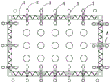
FIG. 1 is a plan view of a lowering structure of the steel cofferdam of the utility model;
FIG. 2 is an enlarged view taken at A in FIG. 1;
FIG. 3 is an elevation view at A in FIG. 1;
FIG. 4 is a schematic plane structure diagram of the steel cofferdam assembled among the steel pipe piles;
fig. 5 is a schematic elevation structure view assembled among steel cofferdam steel pipe piles.
Detailed Description
As shown in fig. 1, fig. 2, fig. 3, the utility model provides a pair of utilize drilling platform steel-pipe pile to carry out the structure that the steel cofferdam was transferred, every curb plate of steel cofferdam 1 is located between two rows of drilling construction platform steel-pipe piles 2, spandrel girder 3 has been set up at 2 tops of two relative steel-pipe piles in steel cofferdam curb plate both sides, just set up a punching jack 4 to the position of steel cofferdam curb plate on the spandrel girder 3, set up a shoulder pole roof beam 5 on the jack, the position of spandrel girder welds a hoisting point 6 respectively on the wall of steel cofferdam curb plate both sides, the hoisting point can adopt bracket or otic placode structure, with the welding of steel cofferdam lateral wall. The lower end of a suspender 7 penetrates through the lifting point 6 and is anchored at the bottom of the lifting point, the upper end of the suspender 7 sequentially penetrates through the bearing beam 3, the jack 4 and the shoulder pole beam 5 from bottom to top, a lower nut 8 is screwed on the top surface of the bearing beam on the suspender, and an upper nut 9 is screwed on the top surface of the shoulder pole beam.
Above-mentioned structure through the jacking and the shrink of adjusting upper nut and lower nut and control jack, can realize transferring step by step of steel cofferdam.
Above-mentioned structure when concrete implementation, for guaranteeing the precision of transferring in steel cofferdam, still can be along vertical many connecting rods of welding 10 on every steel-pipe pile, and many connecting rods weld a gag lever post 11 towards steel cofferdam curb plate one end within a definite time, and the gag lever post can adopt shaped steel, makes gag lever post and cofferdam curb plate contact, can play direction and limiting displacement when the steel cofferdam is transferred.
The steel cofferdam is lowered by adopting the structure, the specific construction method is as follows,
(1) as shown in fig. 4 and 5, after the drilling construction of the pile foundation is completed, when the drilling construction platform is dismantled, two rows of drilling platform steel pipe piles 2 which are closest to two sides of each side plate of the steel cofferdam are reserved according to the size of the steel cofferdam and the design distance between each side plate of the steel cofferdam and the steel casing 12, and a steel cofferdam assembly platform 13 is welded at a height above the water level among the steel pipe piles;
(2) splicing the steel cofferdam 1 into a whole on the steel cofferdam splicing platform 13;
(3) then, as shown in fig. 1, 2 and 3, two lifting points 6 are symmetrically welded at the positions of two sides of the steel cofferdam side plate, which are opposite to the steel casing; a plurality of connecting rods 10 are welded on each steel pipe pile just opposite to the steel cofferdam side plate, limiting rods 11 are welded between the end parts of the connecting rods, and the limiting rods are close to the steel cofferdam side plates;
(4) erecting a bearing beam 3 on the tops of two steel pipe piles which are opposite to the two sides of the steel cofferdam side plate, installing a through jack 4 on the bearing beam 3 at the position opposite to the steel cofferdam side plate, and erecting a shoulder pole beam 5 parallel to the bearing beam on the jack; a hanging rod is penetrated, the lower end of the hanging rod 7 is anchored with a hanging point 6, the upper end of the hanging rod 7 penetrates through the bearing beam 3, the jack 4 and the shoulder pole beam 5, a lower nut 8 is screwed at the position, located on the top surface of the bearing beam, on the hanging rod, and an upper nut 9 is screwed at the position, located on the top surface of the shoulder pole beam, on the hanging rod;
(5) dismantling the steel cofferdam assembly platform among the steel pipe piles to ensure that the gravity of the steel cofferdam 1 is borne by the suspender 7;
(6) when the steel cofferdam is put down, firstly, an upper nut 9 on the suspender, which is positioned on the top surface of the shoulder pole beam, rotates upwards by the height of one stroke of the jack, and then the jack is started to lift upwards by one stroke; the lower nut 8 on the top surface of the bearing beam is rotated upwards by the height of one stroke of the jack, then the jack is returned with oil and contracted, so that the suspender 7 is lowered by the height of one stroke of the jack, and the steel cofferdam 1 is lowered by the corresponding height;
(7) and (5) repeating the step (6), and gradually lowering the steel cofferdam 1 onto the river bed.
Claims (2)
1. The utility model provides an utilize drilling platform steel-pipe pile to carry out structure that steel cofferdam was transferred, its characterized in that: each side plate of the steel cofferdam is positioned between two rows of steel pipe piles of the drilling construction platform, the top parts of two steel pipe piles opposite to the two sides of the steel cofferdam side plate are provided with bearing beams, the bearing beams are provided with a center-penetrating jack opposite to the position of the steel cofferdam side plate, a shoulder pole beam is arranged on the jack, the positions of the bearing beams on the two side walls of the steel cofferdam side plate are respectively welded with a lifting point, the lower end of a suspender penetrates through the lifting point and is anchored at the bottom of the lifting point, the upper end of the suspender sequentially penetrates through the bearing beams, the jack and the shoulder pole beam from bottom to top, the top surface of the bearing beam is in threaded connection with a lower nut, and the top surface of the shoulder pole beam is in threaded connection with an upper nut.
2. The structure for lowering the steel cofferdam by using the steel pipe pile of the drilling platform according to claim 1, wherein: many connecting rods of edge vertical welding on every steel-pipe pile, many connecting rods weld a gag lever post towards steel cofferdam curb plate one end within a definite time, the gag lever post contacts with the cofferdam curb plate.
Priority Applications (1)
| Application Number | Priority Date | Filing Date | Title |
|---|---|---|---|
| CN202120716403.1U CN215165629U (en) | 2021-04-07 | 2021-04-07 | Structure for lowering steel cofferdam by utilizing steel pipe pile of drilling platform |
Applications Claiming Priority (1)
| Application Number | Priority Date | Filing Date | Title |
|---|---|---|---|
| CN202120716403.1U CN215165629U (en) | 2021-04-07 | 2021-04-07 | Structure for lowering steel cofferdam by utilizing steel pipe pile of drilling platform |
Publications (1)
| Publication Number | Publication Date |
|---|---|
| CN215165629U true CN215165629U (en) | 2021-12-14 |
Family
ID=79359905
Family Applications (1)
| Application Number | Title | Priority Date | Filing Date |
|---|---|---|---|
| CN202120716403.1U Active CN215165629U (en) | 2021-04-07 | 2021-04-07 | Structure for lowering steel cofferdam by utilizing steel pipe pile of drilling platform |
Country Status (1)
| Country | Link |
|---|---|
| CN (1) | CN215165629U (en) |
Cited By (2)
| Publication number | Priority date | Publication date | Assignee | Title |
|---|---|---|---|---|
| CN113152472A (en) * | 2021-04-07 | 2021-07-23 | 中交路桥建设有限公司 | Structure and method for lowering steel cofferdam by using steel pipe pile of drilling platform |
| CN114775604A (en) * | 2022-03-08 | 2022-07-22 | 中铁大桥局集团第五工程有限公司 | Construction method for underwater positioning of steel pipe pile implanted into rock-socketed foundation |
-
2021
- 2021-04-07 CN CN202120716403.1U patent/CN215165629U/en active Active
Cited By (2)
| Publication number | Priority date | Publication date | Assignee | Title |
|---|---|---|---|---|
| CN113152472A (en) * | 2021-04-07 | 2021-07-23 | 中交路桥建设有限公司 | Structure and method for lowering steel cofferdam by using steel pipe pile of drilling platform |
| CN114775604A (en) * | 2022-03-08 | 2022-07-22 | 中铁大桥局集团第五工程有限公司 | Construction method for underwater positioning of steel pipe pile implanted into rock-socketed foundation |
Similar Documents
| Publication | Publication Date | Title |
|---|---|---|
| CN108643221B (en) | Offshore wind power assembled bearing platform foundation and construction method thereof | |
| CN215165629U (en) | Structure for lowering steel cofferdam by utilizing steel pipe pile of drilling platform | |
| EP2837554A1 (en) | Partially floating marine platform for offshore wind-power, bridges and marine buildings, and construction method | |
| CN108179735B (en) | Pebble layer large-scale deep water foundation construction platform and pebble layer large-scale deep water foundation construction method | |
| CN109356210A (en) | A kind of pile foundation building inclination rectification cuts stake and underpins position limiting structure and its construction method | |
| CN113152472A (en) | Structure and method for lowering steel cofferdam by using steel pipe pile of drilling platform | |
| CN209243794U (en) | A kind of pile foundation building inclination rectification cuts stake and underpins position limiting structure | |
| CN208167489U (en) | A kind of anti-girder of Single column pier bridge topples device | |
| CN111501756A (en) | Pile-embracing jacket and construction method thereof | |
| CN112609725A (en) | Prefabricated steel open caisson construction method suitable for central urban area | |
| CN111218950A (en) | Offshore wind power single pile and high pile cap foundation steel pipe pile planting shared construction platform | |
| CN216948415U (en) | Movable stable pile platform suitable for offshore steel pile driving | |
| CN215715456U (en) | Combined pile foundation | |
| CN111676799B (en) | Height-adjustable simple cable-stayed diversion trench temporary bridge and construction method thereof | |
| CN212270687U (en) | Steel pipe support temporary pier for inclined main and auxiliary arch cross section | |
| CN114541438A (en) | Steel cofferdam with positioning function and positioning method thereof | |
| CN103726505B (en) | Offshore wind plant wind turbine foundation | |
| CN208039210U (en) | A kind of boulder bed large-sized deep water foundation construction platform | |
| CN216948382U (en) | Single-lifting-point lifting structure arranged on inner wall of double-wall steel cofferdam | |
| CN219011289U (en) | Aquatic tower crane foundation | |
| CN217601478U (en) | Steel cofferdam with locate function | |
| CN215906728U (en) | Floating type drilling construction platform | |
| CN217601477U (en) | Steel cofferdam positioning adjustment system | |
| WO2024007203A1 (en) | New superstructure for high-piled wharf, and construction apparatus and construction method therefor | |
| CN212026321U (en) | Underwater steel structure tower crane foundation |
Legal Events
| Date | Code | Title | Description |
|---|---|---|---|
| GR01 | Patent grant | ||
| GR01 | Patent grant |