CN2151579Y - Dynamic current-feedback magnet exciting DC motor - Google Patents
Dynamic current-feedback magnet exciting DC motor Download PDFInfo
- Publication number
- CN2151579Y CN2151579Y CN93206870U CN93206870U CN2151579Y CN 2151579 Y CN2151579 Y CN 2151579Y CN 93206870 U CN93206870 U CN 93206870U CN 93206870 U CN93206870 U CN 93206870U CN 2151579 Y CN2151579 Y CN 2151579Y
- Authority
- CN
- China
- Prior art keywords
- motor
- armature
- series
- main
- generator
- Prior art date
- Legal status (The legal status is an assumption and is not a legal conclusion. Google has not performed a legal analysis and makes no representation as to the accuracy of the status listed.)
- Expired - Fee Related
Links
Images

Classifications
-
- H—ELECTRICITY
- H02—GENERATION; CONVERSION OR DISTRIBUTION OF ELECTRIC POWER
- H02P—CONTROL OR REGULATION OF ELECTRIC MOTORS, ELECTRIC GENERATORS OR DYNAMO-ELECTRIC CONVERTERS; CONTROLLING TRANSFORMERS, REACTORS OR CHOKE COILS
- H02P7/00—Arrangements for regulating or controlling the speed or torque of electric DC motors
- H02P7/06—Arrangements for regulating or controlling the speed or torque of electric DC motors for regulating or controlling an individual dc dynamo-electric motor by varying field or armature current
- H02P7/18—Arrangements for regulating or controlling the speed or torque of electric DC motors for regulating or controlling an individual dc dynamo-electric motor by varying field or armature current by master control with auxiliary power
- H02P7/34—Arrangements for regulating or controlling the speed or torque of electric DC motors for regulating or controlling an individual dc dynamo-electric motor by varying field or armature current by master control with auxiliary power using Ward-Leonard arrangements
Landscapes
- Engineering & Computer Science (AREA)
- Power Engineering (AREA)
- Control Of Direct Current Motors (AREA)
- Control Of Eletrric Generators (AREA)
- Control Of Multiple Motors (AREA)
Abstract
The utility model relates to a dynamic current feedback magnetizing type DC motor. A shunt or series or compound motor is used for winding an auxiliary shunt field winding to generate higher or lower rotary speed according to the current passing through the armature and drive an auxiliary generator to form a feedback machine set, the auxiliary generator is used for passing to the auxiliary field of a main motor, and the main field is adjusted when the armature current of the main motor is increased. A control interface is used for controlling the output current of the auxiliary generator and then controlling the current of the auxiliary field winding of the main motor to the main magnetizing field. The circuit can be used for generators or motors, and the control system has the characteristic of stable and reliable autogenetic electromechanical form.
Description
The utility model relates to a kind of dynamic current feedback exciting type DC motor.
The tradition direct current machine comprises motor and generator, usually motor has speed control, strengthen torsion feedback compensation and other various demands for control with load, wherein requiring speed and moment of torsion to strengthen to increase in the most common, the same generator then driving change in rotational speed with load causes change in voltage or output voltage is done positive feedback or degenerative demand is also common according to output current.
Main purpose of the present utility model, be to be to provide a kind of dynamic current feedback exciting type DC motor, be a kind of innovation means about above-mentioned DC motor control system, and the low-power that adopts the low to medium price level high reliability is auxiliary electronic and generating set with the main group of motors of control than high-power, its function is good, high and the middle low cost of reliability is the real advantage of the dynamic current feedback exciting type DC motor control circuit of this innovation, and the control system of amplifying feedback or dynamo-electric and solid-state amplifier element formula than traditional magnetic is all making progress aspect reliability and the cost.
The utility model is achieved in that
The utility model mainly is that a kind of mat shunt excitation or series connection or compound motor add around auxiliary shunt field winding, can produce higher according to the institute's armature supply of flowing through size or than the slow-speed of revolution, and in order to drive auxiliary generator formation feedback unit, and the electric energy of auxiliary generator leads to main motor auxiliary magnetic field by this, its excitation mode to main motor auxiliary magnetic field comprises long-pending excitatory with main motor-field winding identical polar, also strengthen with total magnetic field when main armature electric current strengthens thereupon, or the difference that is opposed polarity with main motor-field winding is excitatory, diminish with total magnetic field when main armature electric current strengthens thereupon, but mat work control interface is with the output voltage of control auxiliary generator, or controls its output impedance and to control its output current and then to control above-mentioned master control motor auxiliary magnetic field winding main field is value long-pending excitatory or that difference is excitatory; This dynamic current feedback exciting type DC motor is in fact applicable to generator or motor, said apparatus can reliably be the control system of characteristic and become firm with dynamo-electric kenel in order to replace the expensive regulex or the solid-state and electric mechanical switch loop of other complexity.
Following conjunction with figs. describes full mold example of the present utility model in detail:
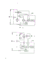
Fig. 1 is depicted as dynamoelectric and power generation unit embodiment circuit diagram in the utility model.
The follow-up motor that Fig. 2 is depicted as feedback unit in the utility model is series at armature, is the embodiment circuit diagram of follow-up motor drive current with the electric loading electric current.
The follow-up motor that Fig. 3 is depicted as feedback unit in the utility model is parallel to main motor series excitation winding, and the pressure drop that forms at the series excitation winding with main motor load electric current is the embodiment circuit diagram that drives the power supply of follow-up motor.
Fig. 4 is depicted as the embodiment circuit diagram that the follow-up motor that feeds back unit in the utility model is parallel to main armature.
Fig. 5 is depicted as main motor shunt excitation formula motor and feeds back that follow-up motor is series at generator armature embodiment circuit diagram in the unit.
Principle of the present utility model and system constitute main with driving in order to the extra power of rotating main group of motors, be included in the DC power supply (power supply that contain controllable voltage) of main group of motors when being motor, or the machinery rotation energy source such as engine or the fluid wheel wing or the motor that the motor revolution are driven during for generator when group of motors; Above-mentioned generator or motor unit are as main group of motors, this main group of motors can be a kind of shunt excitation or series excitation or compound machine, mainly comprise main armature (or the series excitation winding of series connection with it and main armature shunt winding in parallel when the compounding kenel) and the independent main motor auxiliary magnetic field winding that is provided with its armature or power end, and relevant phase tool structures such as end housing, body, axle center, bearing.When main motor is motor, accept the electric power input and do mechanical energy output, when main motor is generator, accepts the mechanical energy input and produce electric energy output; This dynamic current feedback exciting type DC motor group U101, it is required that the motor electric energy of this dynamoelectric and power generation unit is looked control performance, be included as the series field that the armature supply that comes autonomous group of motors drove or be parallel to main armature or be parallel to main motor and do servo-actuated, it is excitatory with the auxiliary magnetic figured stone winding to main motor to produce electric energy, its main composition contains as shown in Figure 1:
Follow-up motor M101: be series-wound motor or shunt excitation or magneto or compound motor, its servo-actuated power supply from:
1. if follow-up motor is a series-wound motor, then this motor is directly connected with the series excitation winding and the armature of aforementioned main motor, or in parallel with the series excitation winding or in parallel with armature; 2. if follow-up motor is the shunt excitation permanent magnet motor, the series excitation group of its armature and main motor and armature is connected or in parallel or in parallel with main armature with main motor series excitation winding then; If 3. compound motor, then its armature and series excitation winding are connected with the armature that main frame is wanted or are in parallel or in parallel with armature with series excitation winding group.
Auxiliary generator C101: by being driven by aforementioned follow-up motor M101, to produce and the corresponding energy output of rotating speed, for excitation main motor auxiliary magnetic field winding CF101, its energy output and main motor speed relation comprise proportional or are inverse ratio, wiring relation on follow-up motor and main motor is decided, and this generator can be DC generator or alternating current machine and rectifying device and constitutes.
Control interface C I101: be output voltage or current value for connection control auxiliary generator, comprise that being series at adjustable impedance on auxiliary generator armature or magnetic field (if the sometimes) output or mat linearity or switching regulator modulation active element by control follow-up motor driving power or mat is series at armature or magnetic field (if sometimes) output, the other end is connected artificial or automatically controlled signal output input.
Now as follows with regard to the principle and the application note of this design:
The follow-up motor that is depicted as feedback unit in this dynamic current feedback exciting type DC motor control circuit as Fig. 2 is series at armature, is the embodiment circuit diagram of follow-up motor drive current with the electric loading electric current, and Fig. 2 is characterized as:
Main group of motors is shunt excitation or has the series-wound motor of series field winding S101 and armature A101 or further have the compound motor of shunt field winding F101, in addition and be provided with auxiliary magnetic field winding CF101 to accept the control of feedback unit U101.
The follow-up motor M101 of feedback unit U101 is series at the armature A101 of main motor, if main armature electric current is excessive, also can make the ratio coupling by the follow-up motor parallel shunt, connects with main armature jointly again.
Auxiliary generator G101 is driven with ejector half motor M101 by aforementioned, to produce and the corresponding energy output of rotating speed, for excitation main motor auxiliary magnetic field winding CF101, its energy output and main motor machine rotation speed relation comprise proportional or are inverse ratio, wiring relation on follow-up motor and main motor is decided, and this generator can be DC generator or alternating current generator and rectifying device and constitutes.
Control interface CI101 is output voltage or current value for connection control auxiliary generator, comprise that mat control follow-up motor driving power or mat are series at adjustable impedance on auxiliary generator armature or magnetic field (if the sometimes) output or mat linearity or switching regulator modulation active element and are series at armature or magnetic field (if sometimes) output, the other end is connected artificial or automatically controlled signal output input.
The follow-up motor that is depicted as feedback unit in this dynamic current feedback exciting type DC motor control circuit as Fig. 3 is parallel to main motor series excitation winding, the pressure drop that forms at the series excitation winding with main motor load electric current is the embodiment circuit diagram that drives the power supply of follow-up motor, and Fig. 3 is characterized as:
Main group of motors is the compound motor that has the series-wound motor of series field winding S101 and armature A101 or further have shunt field winding F101, in addition and be provided with auxiliary magnetic field winding CF101 to accept the control of feedback unit U101.
The follow-up motor M101 of feedback group of motors U101 is in parallel with series excitation winding S101, when main motor is healed big by the electric current of series excitation winding, then the voltage drop ES that forms at series excitation winding two ends is bigger, the terminal voltage of the follow-up motor M101 in parallel with the series excitation winding is improved and faster rotational speed, the coupling of itself and series excitation winding can be selected the tap that elects by series excitation winding S101, or by follow-up motor series connection voltage drop element or vent diverter in parallel.
Auxiliary generator G101 is driven with ejector half motor M101 by aforementioned, to produce and the corresponding energy output of series excitation winding pressure drop, for excitation main motor auxiliary magnetic field winding CF101, its energy output is decided on concerning with main motor speed, and this generator can be DC generator or alternating current generator and rectifying device and constitutes.
Control interface CI101 is output voltage or current value for connection control auxiliary generator, comprise that mat control is series at armature or magnetic field (if sometimes) output with adjustable impedance or the mat linear switch formula modulation active element that motor driven power or mat are series on auxiliary generator armature or magnetic field (if the sometimes) output, the other end is connected artificial or automatically controlled signal output input.
Fig. 4 is depicted as the embodiment circuit diagram that the follow-up motor that feeds back unit in this dynamic current feedback exciting type DC motor control circuit is parallel to main armature, and principal character is among Fig. 4:
Main group of motors is the compound motor that has the series-wound motor of series field winding S101 armature A101 or further have shunt field winding F101, in addition and be provided with auxiliary magnetic field winding CF101 to accept the control of feedback unit U101.
The follow-up motor M101 of feedback unit 101 is parallel to main group of motors master's armature A101, but reaches in order to the coupling mat of the drivings pressure drop that the forms follow-up motor voltage drop element of connecting.
Auxiliary generator G101 is driven with ejector half motor M101 by aforementioned, to produce the energy output corresponding with rotating speed, for excitation main motor auxiliary magnetic field winding CF101, its energy output and main motor speed relation comprise proportional or are inverse ratio, wiring relation on follow-up motor and main motor is decided, and this generator can be DC generator apparatus and constitutes.
Control interface CI101 is for supplying to connect into the output voltage or the current value of control auxiliary generator, comprise that mat control follow-up motor driving power or mat are series at the adjustable impedance of auxiliary generator armature or magnetic field (if sometimes) output or mat linearity or switching regulator adjustment and are shaped on the source element connected in series in armature or magnetic field (if sometimes) output, the other end is connected artificial or automatically controlled signal output input.
Main motor shown in Fig. 5 is that shunt excitation formula motor feeds back the embodiment circuit diagram that follow-up motor in the unit is series at generator armature, and principal character is among Fig. 5:
Main group of motors is for having self-excitation field winding F102 or having separate excitation field winding F103 simultaneously and generator armature G100, in addition and be provided with auxiliary magnetic field winding CF101 to accept the control of feedback unit U101.
Follow-up motor among the feedback unit U101 is series at armature, and is same, can be connected with main armature jointly by the follow-up motor parallel shunt when armature supply is excessive.
Auxiliary generator G101 is driven with ejector half motor 101 by aforementioned, to produce and the corresponding energy output of rotating speed, for excitation main motor auxiliary magnetic field winding CF101, its energy output and main motor speed relation comprise proportional or are inverse ratio, wiring relation on follow-up motor and main motor is decided, and this generator can be DC generator or alternating current generator and rectifying device and constitutes.
Control interface CI101 is output voltage or current value for connection control auxiliary generator, comprise that mat control follow-up motor power or mat are series at adjustable impedance on auxiliary generator armature or magnetic field (if the sometimes) output or mat linearity or switching regulator adjustment and are shaped on the source element connected in series in armature or magnetic field (if sometimes) output, the other end is connected artificial or automatically controlled signal output input.
The feedback relationship that above-mentioned auxiliary unit and main motor form, but in application mat auxiliary unit add mechanicalness flywheel group FW101 or at auxiliary power generation unit output shunt capacitance to regulate the response relation between auxiliary magnetic field winding and main motor; In addition owing in above-mentioned Fig. 2, Fig. 3, Fig. 5 application, the electric energy of follow-up motor strengthens with the armature supply of main motor, follow-up motor power is increased, rotating speed or moment of torsion are strengthened, can further drive the cooling air pump CU100 of main motor with follow-up motor and form that change the cooling flow with main armature current value size be feature, this application can be incorporated in former auxiliary unit or be made up to be become by follow-up motor and cooling air pump separately.
In above-mentioned every application, no matter main motor is motor or generator, all but the mat following relationship is to select required feedback control function: 1. select to receive the feedback electric energy in the autonomous motor of follow-up motor of feedback unit, comprise from armature supply, from the series excitation winding, accept that aforementioned different feedback electric energy are driven or feed back electric energy by many places to drive same feedback unit and form various different relation of following up with main motor from the armature back electromotive force or by many groups of feedback units; 2. the auxiliary power generation unit is that the different kind of series connection, shunt excitation, compounding and electric current, voltage, output characteristic is selected; 3. auxiliary generator and main motor auxiliary magnetic field winding form the polar relationship with the former magnetic pole of main motor, swash for same polarity is long-pending or the antipolarity difference swashs; 4. control interface is to the control of the output current polarity of voltage of feedback unit.
The selection of the above-mentioned terms and conditions of mat work can make this dynamic current feedback exciting type DC motor control circuit obtain the characteristic different with conventional motors, with the selection that provides engineering to use.
Claims (7)
1, a kind of dynamic current feedback exciting type DC motor, it is characterized in that being mainly a kind of mat shunt excitation or series excitation or compound motor adds around auxiliary shunt field winding, and at least one group on mat is with the current drive-type DC motor, this motor can produce higher or than the slow-speed of revolution according to the institute's armature supply of flowing through size, and in order to drive auxiliary generator formation feedback unit, and the electric energy of auxiliary generator leads to the long-pending excitatory of main motor-field winding identical polar by this, or it is excitatory with the difference of main motor-field winding opposed polarity, and mat work control interface is with the output voltage of control auxiliary generator, or controls its output impedance and main field is long-pending swashs or value that difference swashs to control its output current and then to control above-mentioned main motor auxiliary magnetic field winding; This dynamic current feedback exciting type DC motor is moving applicable to generator or motor in actual applications, the energy that is mainly the external main group of motors of rotation of mat drives, be included in the DC power supply (power supply that contain controllable voltage) of main group of motors when being motor, or the machinery rotation energy such as engine or the fluid wheel wing or the motor that the motor revolution are driven during for generator when group of motors; Above-mentioned generator or motor unit are as main group of motors, this main group of motors can be a kind of shunt excitation or series excitation or compound machine, mainly comprise the series excitation winding of main armature or series connection with it and the main armature shunt winding in parallel when the compounding kenel with its armature or power end, and the independent main motor auxiliary magnetic field winding that is provided with, reach associated mechanical structures such as end housing, body, axle center, bearing, when main motor is motor, accept the electric power input and do mechanical energy output, when main motor is generating set, accepts the mechanical energy input and produce electric energy output; This dynamic current feedback exciting type DC motor control circuit is mainly and is provided with one group of feedback feedback unit U101 that motor unit constituted, the motor electric energy of this dynamoelectric and power generation unit is looked the series field that the required armature supply that comprises the autonomous group of motors of origin of control performance drove or be parallel to main armature or be parallel to main motor and is done servo-actuated, excitatory to the auxiliary magnetic field winding of main motor to produce electric energy, its main composition comprises:
Follow-up motor M101: be series-wound motor or shunt excitation or magneto or compound motor, its servo-actuated power supply from: 1. if follow-up motor be series-wound motor, then this motor is directly connected with the series excitation winding and the armature of aforementioned main motor, or or armature parallel connection in parallel with the series excitation winding; 2. if follow-up motor is the shunt excitation permanent magnet motor, then the series excitation winding and the armature series excitation or in parallel or in parallel of its armature and main motor with main armature with main motor series excitation winding; If 3. compound motor, then its armature and series excitation winding are connected with the armature of main motor or are in parallel with the series excitation winding or in parallel with armature;
Auxiliary generator G101, by aforementioned follow-up motor M101 is driven, to produce and the corresponding energy output of rotating speed, for excitation main motor auxiliary magnetic field winding CF101, its energy output and main motor speed relation comprise proportional or are inverse ratio, wiring relation on follow-up motor and main motor is decided, and this generator can be DC generator or alternating current generator and rectifying device and constitutes.
Control interface C1101, for connecting into the output voltage or the current value of control auxiliary generator, comprise that mat control follow-up motor driving power or mat are series at adjustable impedance on auxiliary generator armature or magnetic field (if the sometimes) output or mat linearity or switching regulator modulation active element and are series at armature or magnetic field (if sometimes) output, the other end is connected artificial or automatically controlled signal output input.
2, dynamic current feedback exciting type DC motor as claimed in claim 1, comprising: the follow-up motor of feedback unit is series at armature, is the follow-up motor drive current with the electric loading electric current, and its circuit principal character is:
Main group of motors is shunt excitation or has the series-wound motor of series field winding S101 and armature A101 or further have the compound motor of shunt field winding F101, in addition and be provided with auxiliary magnetic field winding CF101 to accept the control of feedback unit U101;
The follow-up motor M101 of feedback unit U101 is series at the armature A101 of main motor, if main armature electric current is excessive, also can makes the ratio coupling by the follow-up motor parallel shunt and connect with main armature jointly;
Auxiliary generator G101 is driven with ejector half motor M101 by aforementioned, to produce and the corresponding energy output of rotating speed, for excitation main motor auxiliary magnetic field winding C101, its energy output and main motor speed relation comprise proportional or are inverse ratio, wiring relation on follow-up motor and main motor is decided, and this generator can be DC generator or alternating current generator and rectifying device and constitutes;
Control interface C1101 is for supplying to connect into the output voltage or the current value of control auxiliary generator, comprise that mat control follow-up motor driving power or mat are series at adjustable impedance on auxiliary generator armature or magnetic field (if the sometimes) output or mat linearity or switching regulator modulation active element and are series at armature or magnetic field (if sometimes) output, the other end is connected artificial or automatically controlled signal output input.
3, dynamic current feedback exciting type influent stream motor according to claim 1, the follow-up motor that wherein feeds back unit is parallel to main motor series excitation winding, the pressure drop that forms at the series excitation winding with main motor load electric current is the power supply that drives follow-up motor, and its circuit principal character is:
Main group of motors be have series field winding S101 with and the series-wound motor of armature A101 or further have the compound motor of shunt field winding F101, in addition and be provided with auxiliary magnetic field winding CF101 to accept the control of feedback unit U101;
The follow-up motor M101 of feedback group of motors U101 is in parallel with series excitation winding S101, when main motor is healed big by the electric current of series excitation winding, then the voltage drop ES that forms at series excitation winding two ends is bigger, the terminal voltage of the follow-up motor M101 in parallel with the series excitation winding is improved and faster rotational speed, the coupling of itself and series excitation winding contains selection by the series excitation winding S101 tap that elects, or by follow-up motor series connection voltage drop element or vent diverter in parallel;
Auxiliary generator G101 is driven with ejector half motor M101 by aforementioned, to produce and the corresponding energy output of series excitation winding pressure drop, for excitation main motor auxiliary magnetic field winding CF101, its energy output is decided on concerning with main motor speed, and this generator can be DC generator or alternating current generator and rectifying device and constitutes;
Control interface C1101 is for supplying to connect into the output voltage or the current value of control auxiliary generator, comprise that mat control follow-up motor driving power or mat are series at adjustable impedance on auxiliary generator armature or magnetic field (if the sometimes) output or mat linearity or switching regulator modulation active element and are series at armature or magnetic field (if sometimes) output, the other end is connected artificial or automatically controlled signal output input.
4, dynamic current feedback exciting type DC motor according to claim 1, comprising: the follow-up motor of feedback unit, be parallel to main armature, its circuit principal character is:
Main group of motors is the compound motor that has the series-wound motor of series field winding S101 and armature A101 or further have shunt field winding F101, in addition and be provided with auxiliary magnetic field winding CF101 to accept the control of feedback unit U101;
The follow-up motor M101 of feedback unit U101 is parallel to main group of motors master's armature A101, but reaches with the coupling mat series connection voltage drop element of the driving pressure drop that forms follow-up motor;
Auxiliary generator G101 is driven with ejector half motor M101 by aforementioned, to produce and the corresponding energy output of rotating speed, for excitation main motor auxiliary magnetic field winding CF101, its energy output and main motor speed relation comprise proportional or are inverse ratio, wiring relation on follow-up motor and main motor is decided, and this generator can be DC generator apparatus;
Control interface CI101 is for supplying to connect into the output voltage or the current value of control auxiliary generator, comprise that mat control follow-up motor driving power or mat are series at adjustable impedance on auxiliary generator armature or magnetic field (if the sometimes) output or mat linearity or switching regulator adjustment and are shaped on the source element connected in series in armature or magnetic field (if sometimes) output, the other end is connected artificial or automatically controlled signal output input.
5, dynamic current feedback exciting type DC motor according to claim 1, comprising: main motor is a shunt excitation formula motor, and follow-up motor is series at armature in the feedback unit, and its circuit principal character is:
Follow-up motor among the feedback unit U101 is series at armature, and is same, can be connected with main armature jointly by the follow-up motor parallel shunt when armature supply is excessive;
Auxiliary generator G101 is driven with ejector half motor 101 by aforementioned, to produce and the corresponding energy output of rotating speed, for excitation main motor auxiliary magnetic field winding CF101, its energy output and main motor speed relation comprise proportional or are inverse ratio, wiring relation on follow-up motor and main motor is decided, and this generator can be DC generator or alternating current generator and rectifying device and constitutes;
Control interface CI101 is for supplying to connect into the output voltage or the current value of control auxiliary generator, comprise that mat control follow-up motor power or mat are series at adjustable impedance on auxiliary generator armature or magnetic field (if the sometimes) output or mat linearity or switching regulator modulation active element and are series at armature or magnetic field (if sometimes) output, the other end is connected artificial or automatically controlled signal output input.
6, dynamic current feedback exciting type DC motor according to claim 1, it is characterized in that wherein auxiliary unit adds mechanicalness flywheel group FW101 or at auxiliary power generation unit output shunt capacitance to regulate the response relation between auxiliary magnetic field winding and main motor.
7, dynamic current feedback exciting type DC motor according to claim 1, it is characterized in that wherein comprising: main motor is motor or is generator, and the mat following relationship is to select required feedback control function: 1. select to receive the feedback electric energy in the autonomous motor of follow-up motor of feedback unit, comprise from armature supply, from the series excitation winding, accept aforementioned different feedback electric energy and drive or driven by many places feedback electric energy the various different relation of following up of the formation of same feedback unit and main motor from the armature back-emf or by many groups of feedback units; 2. the auxiliary power generation unit is that the different kind of series excitation, shunt excitation, compounding and electric current, voltage, output characteristic is selected; 3. auxiliary generator and main motor auxiliary magnetic field winding form the polar relationship with the former magnetic pole of main motor, swash for same polarity is long-pending or the antipolarity difference swashs; 4. control interface is to the control of the output current polarity of voltage of feedback unit.
Applications Claiming Priority (3)
| Application Number | Priority Date | Filing Date | Title |
|---|---|---|---|
| GB9205865A GB2265475A (en) | 1992-03-18 | 1992-03-18 | Dc motor-generator dynamic feedback control circuit |
| GB9205865.0 | 1992-03-18 | ||
| US08/338,692 US5576613A (en) | 1992-03-18 | 1994-11-14 | DC motor-generator control circuit |
Publications (1)
| Publication Number | Publication Date |
|---|---|
| CN2151579Y true CN2151579Y (en) | 1993-12-29 |
Family
ID=26300552
Family Applications (2)
| Application Number | Title | Priority Date | Filing Date |
|---|---|---|---|
| CN93206870U Expired - Fee Related CN2151579Y (en) | 1992-03-18 | 1993-03-17 | Dynamic current-feedback magnet exciting DC motor |
| CN93103106A Expired - Fee Related CN1035411C (en) | 1992-03-18 | 1993-03-17 | Dynamic current feedback exciting type DC motor |
Family Applications After (1)
| Application Number | Title | Priority Date | Filing Date |
|---|---|---|---|
| CN93103106A Expired - Fee Related CN1035411C (en) | 1992-03-18 | 1993-03-17 | Dynamic current feedback exciting type DC motor |
Country Status (7)
| Country | Link |
|---|---|
| US (1) | US5576613A (en) |
| EP (1) | EP0561623B1 (en) |
| CN (2) | CN2151579Y (en) |
| AT (1) | ATE174456T1 (en) |
| DE (1) | DE69322425T2 (en) |
| ES (1) | ES2125946T3 (en) |
| GB (1) | GB2265475A (en) |
Families Citing this family (13)
| Publication number | Priority date | Publication date | Assignee | Title |
|---|---|---|---|---|
| US5711705A (en) * | 1995-05-25 | 1998-01-27 | Flanders Filters, Inc. | Isolation work station |
| US5571796A (en) * | 1995-06-06 | 1996-11-05 | Alberta Research Council | Administration of valienamine-related disaccharide compounds in reducing inflammation in a sensitized mammal arising from exposure to an antigen |
| CN1050474C (en) * | 1996-07-12 | 2000-03-15 | 青岛大学 | Electric machine non-linear exciter automatic controller |
| JP2003102199A (en) * | 2001-07-19 | 2003-04-04 | Yamaha Motor Co Ltd | Inverter system generator |
| JP2006217780A (en) | 2005-02-07 | 2006-08-17 | Yamaha Motor Co Ltd | Inverter ac power plant |
| US7888916B1 (en) | 2007-12-26 | 2011-02-15 | Taylor Gregory G | Power conditioner for circuit breaker panel and method of use |
| US8097967B2 (en) * | 2008-06-30 | 2012-01-17 | Demand Energy Networks, Inc. | Energy systems, energy devices, energy utilization methods, and energy transfer methods |
| US8319358B2 (en) * | 2008-06-30 | 2012-11-27 | Demand Energy Networks, Inc. | Electric vehicle charging methods, battery charging methods, electric vehicle charging systems, energy device control apparatuses, and electric vehicles |
| DE102010024246A1 (en) * | 2010-06-18 | 2011-12-22 | Netstal-Maschinen Ag | Method and device for operating a driven axle in a machine tool |
| US9525285B2 (en) | 2011-06-13 | 2016-12-20 | Demand Energy Networks, Inc. | Energy systems and energy supply methods |
| BR212014000281U2 (en) * | 2011-07-14 | 2019-09-24 | Metalurgica Siemsen Ltda | constructive arrangement in blender |
| US9214880B2 (en) * | 2012-06-11 | 2015-12-15 | Tai-Her Yang | Switch type DC electric machine having auxiliary excitation winding and conduction ring and brush |
| RU2679594C1 (en) * | 2018-05-07 | 2019-02-12 | Александр Абромович Часовской | Electromechanical device |
Family Cites Families (13)
| Publication number | Priority date | Publication date | Assignee | Title |
|---|---|---|---|---|
| GB609952A (en) * | 1946-03-26 | 1948-10-08 | Stephen Edward Pritt | Improvements in direct-current electric traction equipments |
| GB665842A (en) * | 1947-08-28 | 1952-01-30 | British Thomson Houston Co Ltd | Improvements in and relating to electric motor control systems |
| GB649556A (en) * | 1948-10-18 | 1951-01-31 | English Electric Co Ltd | Improvements relating to control systems for dynamo electric machines |
| GB1003312A (en) * | 1960-10-31 | 1965-09-02 | Wm Wadsworth & Sons Ltd | Improvements in variable speed electric drives |
| US3470434A (en) * | 1966-09-09 | 1969-09-30 | Westinghouse Electric Corp | Electrical drive and method of operating such drive |
| US3569809A (en) * | 1968-01-22 | 1971-03-09 | Mobility Systems Inc | Dc electric motor control systems |
| DE2047212C3 (en) * | 1970-09-25 | 1974-04-11 | Siemens Ag, 1000 Berlin U. 8000 Muenchen | Leonard drive device in which the field winding of the Leonard generator is fed via a rotary transformer to control the speed of the Leonard motor |
| US3867678A (en) * | 1973-02-15 | 1975-02-18 | Bucyrus Erie Co | Method and means for measuring the torque delivered by an electric motor |
| US3997824A (en) * | 1973-04-20 | 1976-12-14 | General Electric Company | Electrical propulsion system and control arrangements therefor |
| US4323830A (en) * | 1980-05-21 | 1982-04-06 | The Franklin Institute | DC Motor control using motor-generator set with controlled generator field |
| US4408147A (en) * | 1981-03-19 | 1983-10-04 | Jonathan Gabel | Method and apparatus for high efficiency operation of electromechanical energy conversion devices |
| US5281905A (en) * | 1989-12-14 | 1994-01-25 | Sundstrand Corporation | Induction machine based hybrid aircraft engine starting/generating power system |
| GB2269245B (en) * | 1992-07-30 | 1996-05-22 | Yang Tai Her | Feedback type motor-generator control circuit |
-
1992
- 1992-03-18 GB GB9205865A patent/GB2265475A/en not_active Withdrawn
-
1993
- 1993-03-17 AT AT93302011T patent/ATE174456T1/en not_active IP Right Cessation
- 1993-03-17 EP EP93302011A patent/EP0561623B1/en not_active Expired - Lifetime
- 1993-03-17 CN CN93206870U patent/CN2151579Y/en not_active Expired - Fee Related
- 1993-03-17 ES ES93302011T patent/ES2125946T3/en not_active Expired - Lifetime
- 1993-03-17 DE DE69322425T patent/DE69322425T2/en not_active Expired - Fee Related
- 1993-03-17 CN CN93103106A patent/CN1035411C/en not_active Expired - Fee Related
-
1994
- 1994-11-14 US US08/338,692 patent/US5576613A/en not_active Expired - Fee Related
Also Published As
| Publication number | Publication date |
|---|---|
| DE69322425D1 (en) | 1999-01-21 |
| EP0561623A3 (en) | 1994-02-16 |
| EP0561623B1 (en) | 1998-12-09 |
| GB2265475A (en) | 1993-09-29 |
| EP0561623A2 (en) | 1993-09-22 |
| GB9205865D0 (en) | 1992-04-29 |
| US5576613A (en) | 1996-11-19 |
| CN1077574A (en) | 1993-10-20 |
| DE69322425T2 (en) | 1999-06-24 |
| ES2125946T3 (en) | 1999-03-16 |
| CN1035411C (en) | 1997-07-09 |
| ATE174456T1 (en) | 1998-12-15 |
Similar Documents
| Publication | Publication Date | Title |
|---|---|---|
| CN2151579Y (en) | Dynamic current-feedback magnet exciting DC motor | |
| CN1032343C (en) | AC motor drive system | |
| CN1071956C (en) | Current control apparatus in switched reluctance motor | |
| KR20080089448A (en) | Virtual moving air gap for an axial flux permanent magnet motor with dual stators | |
| KR940000306A (en) | AC variable speed drive device and electric vehicle drive system using the device | |
| CN1373548A (en) | Transportation system and motor-generator | |
| GB2117144A (en) | Electric motor drive arrangement | |
| CN2054230U (en) | Brushless dc motor | |
| Yamai et al. | Optimal switched reluctance motor drive for hydraulic pump unit | |
| US5565723A (en) | Mechanical power transmission assembly | |
| US6633151B2 (en) | Electric vehicle drive system | |
| Torok et al. | The world's simplest motor for variable speed control? The Cyrano motor, a PM-biased SR-motor of high torque density | |
| US5408166A (en) | Dynamic current feedback magnetizing type series or compound DC motor-generator control circuit | |
| CN113346638A (en) | Three-phase parallel magnetic circuit motor | |
| CN1217475C (en) | Control method of bridge electric transverter | |
| CN1242544C (en) | Switch reluctance machine drive | |
| CN1032508C (en) | DC divided or compound excitation motor with controllable dynamic property and circuit device thereof | |
| CN2334120Y (en) | AC motor | |
| WO1992005626A1 (en) | Apparatus for controlling series wound d.c. machines | |
| US5519276A (en) | DC compound motor having an auxiliary generator which supplies power for shunt field winding excitation | |
| CN1027947C (en) | Variable brush step speed regulation dc motor | |
| CN1929266A (en) | Method for making brushless DC velocity measuring dynamo | |
| CN116488526A (en) | Method for detecting relative position of stator and rotor by aid of auxiliary coil | |
| CN1937395A (en) | Coutrol apparatus of synchronous motor and control method therefor | |
| RU2217858C2 (en) | Speed control device for dc reversing motor with two independent series-connected field windings |
Legal Events
| Date | Code | Title | Description |
|---|---|---|---|
| C14 | Grant of patent or utility model | ||
| GR01 | Patent grant | ||
| C19 | Lapse of patent right due to non-payment of the annual fee | ||
| CF01 | Termination of patent right due to non-payment of annual fee |