CN215073739U - Air-floating suction nozzle module - Google Patents
Air-floating suction nozzle module Download PDFInfo
- Publication number
- CN215073739U CN215073739U CN202120956374.6U CN202120956374U CN215073739U CN 215073739 U CN215073739 U CN 215073739U CN 202120956374 U CN202120956374 U CN 202120956374U CN 215073739 U CN215073739 U CN 215073739U
- Authority
- CN
- China
- Prior art keywords
- air
- negative pressure
- suction nozzle
- floating
- shaft
- Prior art date
- Legal status (The legal status is an assumption and is not a legal conclusion. Google has not performed a legal analysis and makes no representation as to the accuracy of the status listed.)
- Active
Links
- 230000000149 penetrating effect Effects 0.000 claims description 5
- 238000007789 sealing Methods 0.000 claims description 3
- 230000000694 effects Effects 0.000 description 13
- 238000010586 diagram Methods 0.000 description 4
- 230000005496 eutectics Effects 0.000 description 4
- 238000000034 method Methods 0.000 description 3
- 238000003466 welding Methods 0.000 description 3
- 238000010521 absorption reaction Methods 0.000 description 2
- ZZUFCTLCJUWOSV-UHFFFAOYSA-N furosemide Chemical group C1=C(Cl)C(S(=O)(=O)N)=CC(C(O)=O)=C1NCC1=CC=CO1 ZZUFCTLCJUWOSV-UHFFFAOYSA-N 0.000 description 2
- 239000012528 membrane Substances 0.000 description 2
- 238000012986 modification Methods 0.000 description 2
- 230000004048 modification Effects 0.000 description 2
- 238000000926 separation method Methods 0.000 description 2
- OKTJSMMVPCPJKN-UHFFFAOYSA-N Carbon Chemical compound [C] OKTJSMMVPCPJKN-UHFFFAOYSA-N 0.000 description 1
- 230000009286 beneficial effect Effects 0.000 description 1
- 238000007664 blowing Methods 0.000 description 1
- 125000004122 cyclic group Chemical group 0.000 description 1
- 238000006073 displacement reaction Methods 0.000 description 1
- 229910002804 graphite Inorganic materials 0.000 description 1
- 239000010439 graphite Substances 0.000 description 1
- 230000005484 gravity Effects 0.000 description 1
- 239000000463 material Substances 0.000 description 1
- 230000001105 regulatory effect Effects 0.000 description 1
- 238000001179 sorption measurement Methods 0.000 description 1
- 125000003003 spiro group Chemical group 0.000 description 1
- 230000003068 static effect Effects 0.000 description 1
Images


Landscapes
- Manipulator (AREA)
Abstract
The utility model relates to an air-floating suction nozzle module, which comprises an air-floating shaft, a fixed seat and a suction nozzle; the fixed seat is provided with a movable cavity for the air floating shaft to move up and down, the lower end of the air floating shaft is provided with a suction nozzle groove, and the side wall of the air floating shaft is provided with a first negative pressure air passage and a second negative pressure air passage which are communicated with the suction nozzle groove and are respectively used for adsorbing a suction nozzle and a workpiece matched with the air passage in the suction nozzle; a negative pressure part and a positive pressure part are axially arranged on the inner wall of the movable cavity, and a first negative pressure air port and a second negative pressure air port are respectively arranged on the negative pressure part corresponding to the first negative pressure air passage and the second negative pressure air passage; the positive pressure part is provided with a positive pressure air passage for forming an air flow film between the air floating shaft and the inner wall of the movable cavity so as to separate the air floating shaft from the fixed seat; when the assembly targets in place, the range of the distance between the side wall of the air floating shaft and the negative pressure part is 3-5 microns, the air floating shaft and the inner wall of the movable cavity are separated through the positive pressure air channel to avoid friction, so that the stability of the pressure of the suction nozzle module is ensured, and the external interference is reduced.
Description
Technical Field
The utility model relates to an eutectic welding technical field, in particular to air supporting formula suction nozzle module.
Background
The eutectic bonding technique has high requirements on the functional appearance of the chip besides selection of eutectic materials and control of bonding temperature. The integrated circuit chip of high power often all can paste the chip of many types of specifications on a circuit board, the chip of different specifications needs the cooperation of different suction nozzles to paste the dress, however the suction nozzle mechanism on the existing equipment changes the trouble inefficiency of suction nozzle process, when carrying out the eutectic welding, the pressure size that the suction nozzle applyed also directly produces the direct influence to the quality of welding above the chip, nevertheless to different chip products, the pressure of applyingly also all is different, it is unequal to tens of grams of pressure from several grams of pressure, the static friction that produces by the guide rail in the motion process is pushed down to current suction nozzle mechanism suction nozzle can't be avoided, then hardly realize or unstable when exerting little pressure.
SUMMERY OF THE UTILITY MODEL
An object of the utility model is to provide an air supporting formula suction nozzle module to prior art not enough, this air supporting formula suction nozzle module can solve above-mentioned problem well.
In order to meet the above requirements the utility model provides a technical scheme that its technical problem adopted is:
the air floating type suction nozzle module comprises an air floating shaft, a fixed seat and a suction nozzle; the fixed seat is provided with a movable cavity for the air floating shaft to move up and down, the lower end of the air floating shaft is provided with a suction nozzle groove, and the side wall of the air floating shaft is provided with a first negative pressure air passage and a second negative pressure air passage which are communicated with the suction nozzle groove and are respectively used for adsorbing the suction nozzle and a workpiece matched with the air passage in the suction nozzle; a negative pressure part and a positive pressure part are axially arranged on the inner wall of the movable cavity, and a first negative pressure air port and a second negative pressure air port are respectively arranged on the negative pressure part corresponding to the first negative pressure air passage and the second negative pressure air passage; the positive pressure part is provided with a positive pressure air passage for forming an air flow film between the air floating shaft and the inner wall of the movable cavity so as to separate the air floating shaft from the fixed seat; when assembled in place, the distance between the side wall of the air bearing shaft and the negative pressure part ranges from 3 to 5 micrometers.
Air supporting formula suction nozzle module, wherein, the negative pressure position is located the middle part in activity chamber, the upper portion and the lower part in activity chamber all are equipped with the malleation position.
Air supporting formula suction nozzle module, wherein, the top of fixing base is equipped with the air supporting end cover, the upper end of air supporting axle with the air supporting end cover is connected.
Air supporting formula suction nozzle module, wherein, the top of air supporting axle is equipped with its rotatory rotary mechanism of drive, the air supporting axle with rotary mechanism passes through elastic component and connects.
The air-floating suction nozzle module of the utility model, wherein the rotating mechanism is a motor, and the elastic component comprises a spring leaf coaxially connected with the air-floating shaft, a spring seat for fixing the spring leaf and a connecting cover for connecting the spring seat and the motor; the spring seat is provided with a positioning groove matched with the spring piece, the bottom surface of the positioning groove is provided with a movable through hole for the vertical deformation of the middle part of the spring piece, a fixing piece for fixing the spring piece is arranged in the positioning groove, and the connecting cover is detachably connected with the spring seat.
Air supporting formula suction nozzle module, wherein, seted up on the spring leaf and reduced the trompil of the stress of spring leaf, the trompil is equipped with a plurality ofly, and is a plurality of the trompil is followed the radial direction multilayer of spring leaf distributes.
Air supporting formula suction nozzle module, wherein, the suction nozzle groove is loudspeaker form, the bottom in suction nozzle groove is equipped with switches on the room, when the assembly targets in place, air flue in the suction nozzle with switch on the room and switch on, first negative pressure air flue intercommunication the oblique lateral wall in suction nozzle groove, second negative pressure air flue intercommunication switch on the room.
Air supporting formula suction nozzle module, wherein, first negative pressure air flue's gas outlet with second negative pressure air flue's gas outlet is followed the axial direction of air supporting axle distributes, correspond respectively on the negative pressure position first negative pressure air flue with second negative pressure air flue is equipped with first ring channel and second ring channel, the stroke groove has vertically been seted up on the malleation position, malleation air flue intercommunication the stroke groove, the stroke groove is equipped with a plurality ofly and is annular evenly distributed and is in on the malleation position.
The air-floating suction nozzle module of the utility model, wherein the fixing base comprises an air-distributing shaft and an air-distributing shaft seat sleeved outside the air-distributing shaft; the gas distribution shaft is provided with a through hole penetrating through two ends of the gas distribution shaft, and the through hole forms the movable cavity; the outer side wall of the air distribution shaft is provided with a sealing ring for separating the first negative pressure air port, the second negative pressure air port and the positive pressure air passage, and the air distribution shaft seat is provided with a first air nozzle, a second air nozzle and a third air nozzle corresponding to the first negative pressure air port, the second negative pressure air port and the positive pressure air passage respectively; the upper end of the gas distribution shaft is provided with a positioning table, and the lower end of the gas distribution shaft penetrates out of the movable cavity and is fixedly connected with the gas distribution shaft seat through a stop piece.
The beneficial effects of the utility model reside in that: the utility model discloses an air supporting formula suction nozzle module, in operation, with malleation air flue intercommunication positive pressure air supply, form the high-speed air current membrane of one deck through malleation air flue between air supporting axle and activity intracavity wall, and then make air supporting axle and the separation contactless of activity intracavity wall, and then avoid the two to rub each other, with the stability of the pressure of guaranteeing the suction nozzle module, reduce external disturbance, realize the absorption of suction nozzle fixed and work piece through first negative pressure air flue and second negative pressure air flue simultaneously, and through the interval restriction between the negative pressure position with activity intracavity wall and the air supporting axle between 3 to 5 microns, and then avoid malleation air flue and negative pressure air flue to interfere with each other, guarantee the normal clear of work.
Drawings
In order to more clearly illustrate the embodiments of the present invention or the technical solutions in the prior art, the present invention will be further described below with reference to the accompanying drawings and embodiments, wherein the drawings in the following description are only some embodiments of the present invention, and for those skilled in the art, other drawings can be obtained without inventive work according to the drawings:
fig. 1 is an overall structure diagram of the air-floating suction nozzle module of the present invention.
Fig. 2 is a top view of the overall structure of the air-floating suction nozzle module according to the present invention.
Fig. 3 is a structural diagram of the elastic component of the air-floating suction nozzle module of the present invention.
Fig. 4 is a top view of the spring plate of the air-floating suction nozzle module of the present invention.
Fig. 5 is an assembly view of the suction nozzle and the air floating shaft of the air floating suction nozzle module of the present invention.
Fig. 6 is an exploded bottom view of the air floating suction nozzle module according to the present invention.
Fig. 7 is a structural diagram of the air distributing shaft of the air floating type suction nozzle module of the present invention.
Fig. 8 is a structural diagram of the air floating shaft of the air floating type suction nozzle module of the present invention.
Fig. 9 is a cross-sectional view of the first negative pressure air passage in the air floating shaft of the air floating suction nozzle module of the present invention.
Fig. 10 is a cross-sectional view of a second negative pressure air passage in the air floating shaft of the air floating suction nozzle module of the present invention.
Fig. 11 is a horizontal cross-sectional view of the second negative pressure air passage in the air floating shaft of the air floating suction nozzle module of the present invention.
Fig. 12 is a horizontal cross-sectional view of the first negative pressure air passage in the air floating shaft of the air floating suction nozzle module of the present invention.
Fig. 13 is a cross-sectional view of the air-distributing shaft of the air-floating suction nozzle module of the present invention.
Fig. 14 is a cross-sectional view of the air distributing shaft seat of the air floating type suction nozzle module of the present invention.
Fig. 15 is a cross-sectional view of the air distributing shaft seat of the air floating type suction nozzle module of the present invention.
FIG. 16 is a cross-sectional view of the whole structure of the air-floating suction nozzle module of the present invention
Detailed Description
In order to make the objects, technical solutions and advantages of the embodiments of the present invention clearer, a clear and complete description will be given below with reference to the technical solutions of the embodiments of the present invention, and it is obvious that the described embodiments are some, but not all embodiments of the present invention. Based on the embodiments of the present invention, all other embodiments obtained by a person of ordinary skill in the art without creative efforts belong to the protection scope of the present invention.
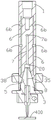
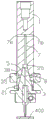
The air-floating suction nozzle module of the preferred embodiment of the present invention, as shown in fig. 1-16, includes an air-floating shaft 1, a fixing base 2 and a suction nozzle 3; the fixed seat 2 is provided with a movable cavity 4 for the air floating shaft 1 to move up and down, the lower end of the air floating shaft 1 is provided with a suction nozzle groove 5 for fixedly mounting a suction nozzle 3, the side wall of the air floating shaft 1 is provided with a first negative pressure air passage 6 and a second negative pressure air passage 7 which are communicated with the suction nozzle groove 5 and are respectively used for adsorbing the suction nozzle 3 and an air passage 8 matched with the suction nozzle 3 to adsorb a workpiece 400, the air outlets of the first negative pressure air passage 6 and the second negative pressure air passage 7 can be arranged on the same horizontal plane or on horizontal planes at different heights, and different configuration modes can be selected according to different application occasions; a negative pressure part 100 and a positive pressure part 200 are axially arranged on the inner wall of the movable cavity 4, and a first negative pressure air port 6a and a second negative pressure air port 7a are respectively arranged on the negative pressure part 100 corresponding to the first negative pressure air passage 6 and the second negative pressure air passage 7; a positive pressure air passage 9 is arranged on the positive pressure part 200 in a penetrating way and is used for forming a high-speed airflow film between the air floating shaft 1 and the inner wall of the movable cavity 4 so as to separate the air floating shaft 1 from the fixed seat 2; when the assembly targets in place, the scope of the distance between the lateral wall of air supporting shaft 1 and negative pressure position 100 is 3 to 5 microns, in operation, with malleation air flue 9 intercommunication positive pressure air supply, form the high-speed air current membrane of one deck between air supporting shaft 1 and activity chamber 4 inner wall through malleation air flue 9, and then make air supporting shaft 1 and the separation contactless of activity chamber 4 inner wall, and then avoid the two looks mutual friction, with the stability of the pressure of guaranteeing the suction nozzle module, reduce external disturbance, realize the absorption of fixed and the work piece of suction nozzle 3 through first negative pressure air flue 6 and second negative pressure air flue 7 simultaneously, and through the interval restriction between negative pressure position 100 with activity chamber 4 inner wall and air supporting shaft 1 between 3 to 5 microns, and then avoid malleation air flue 9 and negative pressure air flue to interfere with each other, guarantee the normal clear of work.
Preferably, the middle part in activity chamber 4 is located to negative pressure position 100, and the upper portion and the lower part in activity chamber 4 all are equipped with malleation position 200, and through setting up two malleation positions 200, further through the air current in the malleation air flue 9 on two malleation positions 200 to the upper and lower both ends of air supporting shaft 1 blow and float and spacing, prevent the incline of air supporting shaft 1, set up negative pressure position 100 reasonable in the middle of two malleation positions 200 with the setting outside spare part of conveniently arranging.
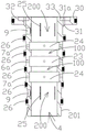
Preferably, the top of fixing base 2 is equipped with air supporting end cover 10, the air supporting end cover is discoid specifically, the upper end of air supporting axle 1 is passed through connecting piece 11 and can be dismantled with air supporting end cover 10 and be connected, through the interval of rational allocation air supporting end cover 10 and activity chamber 4 upper end, when being located the gas in the malleation air flue 9 on activity chamber 4 upper portion and blowing off activity chamber 4, high velocity air alright blow air supporting end cover 10 upwards and float, through setting up predetermined pressure alright offset whole or part of the dead weight of air supporting axle 1 and suction nozzle 3, be convenient for the pressure regulation and control of suction nozzle 3, specifically, connecting piece 11 is threaded connection axle and coaxial through air supporting end cover 10, in order to make things convenient for the equipment dismantlement.
Preferably, a rotating mechanism 12 for driving the air floating shaft 1 to rotate is arranged above the air floating shaft 1, so that the air floating shaft 1 is driven to rotate after the suction nozzle 3 sucks the chip, and the horizontal deflection angle of the chip is adjusted, so as to ensure the processing precision, the air floating shaft 1 is connected with the rotating mechanism 12 through an elastic component 13, in order to ensure the firmness of the equipment, a base 14 for supporting and fixing the rotating mechanism 12 is arranged on the fixing base 2, the base 14 is of a cylindrical structure with openings at two ends so as to conveniently arrange the elastic component 13 in the base, the equipment volume is reduced, the air floating shaft 1 can have a certain moving range in the longitudinal direction by utilizing the easy deformability of the elastic component 13, meanwhile, small-range pressure regulation and control are provided for the suction nozzle 3, the regulating and control range is specifically between 10 g and 50g, so as to reduce the chip damage report rate.
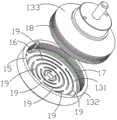
Preferably, the rotating mechanism 12 is a motor, specifically a 50W servo motor to ensure control accuracy, and the elastic component 13 includes a spring plate 131 coaxially connected with the air floating shaft 1, a spring seat 132 for fixing the spring plate 131, and a connecting cover 133 for connecting the spring seat 132 and the motor; in order to ensure the stress balance of the air floating shaft 1, the air floating shaft 1 is fixed at the central position of the spring piece 131, and the spring piece 131 can be arranged into a disc shape, a square shape or a rectangular shape; the spring seat 132 is provided with a positioning groove 15 adapted to the spring plate 131, the bottom surface of the positioning groove 15 is provided with a movable through hole 16 for the middle part of the spring plate 131 to deform up and down, specifically, the connecting piece 11 is coaxially fixed with the spring plate 131 and the air floating shaft 1, the positioning groove 15 is internally provided with a fixing piece for fixing the spring plate 131, the connecting cover 133 is detachably connected with the spring seat 132, specifically, the inner side wall of the positioning groove 15 is provided with a first thread 17, the outer side wall of the connecting cover 133 is provided with a second thread 18 adapted to the first thread 17, thereby facilitating the assembly and disassembly of the spring seat 132 and the connection cover 133, and simultaneously, when the connection cover 133 is screwed to the bottom surface of the positioning slot 15, the spring plate 131 is clamped by the spring seat 132, the connection cover 133 forms a fixing member, and in addition, the fixing member can be realized by a screw, the spring plate 131 can be fixed in the positioning slot 15, to reduce friction, a fixed bearing 37 is coaxially provided on the base 14 to which the cover 133 is fixedly attached.
Preferably, this scheme spring leaf 131 is discoid, set up the trompil 19 that reduces the stress of spring leaf 131 on the spring leaf 131, trompil 19 is equipped with a plurality ofly, a plurality of trompils 19 are along the radial direction multilayer distribution of spring leaf 131, in order to match the shape of spring leaf 131 and guarantee the stress equilibrium of spring leaf 131, a plurality of trompils 19 all are half circular arc and two liang of concentric opposition each other, every two liang of relative trompil 19 constitute a set of, the center that multiunit trompil 19 used spring leaf 131 is cyclic annular distribution as the centre of a circle, and every two sets of adjacent trompils 19 of rotation declination is 90, in addition, in order to monitor the pressure parameter in the course of working, can dispose the pressure sensor 36 that detects the elasticity when the spring leaf deformation.
Preferably, the nozzle slot 5 is a horn shape with a larger opening end, the bottom of the nozzle slot 5 is provided with a conduction chamber 20, when the assembly is in place, the air passage 8 in the nozzle 3 is conducted with the conduction chamber 20, the inclined side wall of the nozzle slot 5 is provided with an annular diversion trench 38, the first negative pressure air passage 6 is communicated with the annular diversion trench 38 to fix the nozzle 3 in the nozzle slot 5 in an adsorption manner, the second negative pressure air passage 7 is communicated with the conduction chamber 20 to be used for conducting the air passage 8 in the nozzle 3 and further for adsorbing a chip, in order to prevent the nozzle 3 from rotating, the nozzle 3 is provided with a positioning pin 21, and the inner wall of the nozzle slot 5 is further provided with a clamping groove 22 for the positioning pin to clamp 21.
Preferably, the air outlet 6b of the first negative pressure air passage 6 and the air outlet 7b of the second negative pressure air passage 7 are distributed along the axial direction of the air floating shaft 1, a plurality of air outlets 6b and 7b of the first negative pressure air passage 6 and the second negative pressure air passage 7 are arranged, a first annular groove 23 and a second annular groove 24 are respectively arranged on the negative pressure part 100 corresponding to the first negative pressure air passage 6 and the second negative pressure air passage 7 to form a balanced air chamber, when the air floating shaft 1 rotates and moves up and down, the first negative pressure air passage 6 and the first negative pressure air port 6a are ensured to be communicated with each other constantly, and the second negative pressure air passage 7 and the second negative pressure air port 7a are communicated with each other constantly; the stroke groove 25 has vertically been seted up on malleation position 200, malleation air flue 9 intercommunication stroke groove 25, stroke groove 25 is equipped with a plurality ofly and is annular evenly distributed on malleation position 200, can guarantee the even atress of lateral wall circumference of air supporting shaft 1 on the one hand, on the other hand also can guarantee that its lateral wall axial atress is balanced and the lifting surface area is more when air supporting shaft 1 moves about from top to bottom, guarantee air supporting shaft 1 and float air stability, it needs to explain, the length of the longitudinal width of first ring channel 23 and second ring channel and stroke groove 25 all is greater than or equal to the stroke of air supporting shaft 1.
Preferably, the fixing seat 2 comprises a gas distribution shaft 201 and a gas distribution shaft seat 202 sleeved outside the gas distribution shaft 201, and a fixing hole 300 for fixing the gas distribution shaft 201 is arranged on the gas distribution shaft seat 202 in a penetrating manner for convenient processing; the air distribution shaft 201 is provided with a through hole penetrating through two ends thereof, the through hole forms a movable cavity 4, the outer side wall of the air distribution shaft 201 is provided with a sealing ring 26 for separating a first negative pressure air port 6a, a second negative pressure air port 7a and a positive pressure air passage 9 so as to reduce the mutual interference degree of air pressure in each air passage, the air distribution shaft seat 202 is provided with a first air nozzle 27, a second air nozzle 28 and a third air nozzle 29 corresponding to the first negative pressure air port 6a, the second negative pressure air port 7a and the positive pressure air passage 9 respectively, and the positive pressure air passages 9 on the two positive pressure parts 200 are communicated through a communicating air passage 39 arranged in the air distribution shaft seat 202 and supply air through the third air nozzle 29 in consideration of cost and equipment attractiveness; the upper end of the air-distributing shaft 201 is provided with an annular positioning table 30, the air-distributing shaft base 202 is provided with a limiting groove 40 adapted to the positioning table 30, in order to further ensure the stability of the air-floating end cap 10, the positioning table 30 is provided with a plurality of air outlet holes 31 for communicating with the positive pressure air channel 9 positioned at the upper part of the movable cavity 4, the air outlet holes 31 are provided with a plurality of air outlet holes 31 which are uniformly distributed on the positioning table 30 in an annular shape, the upper surface of the positioning table 30 is further provided with an annular groove 32 communicated with the plurality of air outlet holes 31, an air flow buffer ring 33 is arranged in the annular groove 32, the air flow buffer ring 33 is provided with air outlet through holes 31a corresponding to the air outlet holes 31, the air flow buffer ring 33 can be made of graphite and has a buffer function, when positive pressure air flows enter the air outlet holes 31, the positive pressure flows are further ejected through the air outlet through holes 31a to blow up the end cap 10, so as to offset the gravity of the air-floating shaft 1, the suction nozzle and other components, the pressure regulation is facilitated; the lower extreme of minute gas shaft 201 is worn out movable chamber 4 and is passed through end position piece 34 and branch gas shaft seat 202 fixed connection, end position piece 34 specifically be with the nut of minute gas shaft 201 spiro union, location platform 30 cooperation end position piece alright with minute gas shaft 201 and branch gas shaft seat 202 fixed connection, in order to control the stroke about the air supporting shaft 1, the below that lies in end position piece 34 on the air supporting shaft 1 is equipped with stroke stopper 35, further cooperate end position piece 34 alright adjustment air supporting shaft 1's upper and lower displacement scope through the upper and lower position of adjustment stroke stopper 35.
It will be understood that modifications and variations can be made by persons skilled in the art in light of the above teachings and all such modifications and variations are considered to be within the scope of the invention as defined by the following claims.
Claims (9)
1. An air-floating type suction nozzle module is characterized by comprising an air-floating shaft, a fixed seat and a suction nozzle; the fixed seat is provided with a movable cavity for the air floating shaft to move up and down, the lower end of the air floating shaft is provided with a suction nozzle groove, and the side wall of the air floating shaft is provided with a first negative pressure air passage and a second negative pressure air passage which are communicated with the suction nozzle groove and are respectively used for adsorbing the suction nozzle and a workpiece matched with the air passage in the suction nozzle; a negative pressure part and a positive pressure part are axially arranged on the inner wall of the movable cavity, and a first negative pressure air port and a second negative pressure air port are respectively arranged on the negative pressure part corresponding to the first negative pressure air passage and the second negative pressure air passage; the positive pressure part is provided with a positive pressure air passage for forming an air flow film between the air floating shaft and the inner wall of the movable cavity so as to separate the air floating shaft from the fixed seat; when assembled in place, the distance between the side wall of the air bearing shaft and the negative pressure part ranges from 3 to 5 micrometers.
2. The air-floating suction nozzle module set forth in claim 1, wherein said negative pressure portion is provided in the middle of said active cavity, and said positive pressure portion is provided in both the upper and lower portions of said active cavity.
3. The air-floating suction nozzle module as claimed in claim 2, wherein an air-floating end cap is disposed above the fixing base, and an upper end of the air-floating shaft is connected to the air-floating end cap.
4. The air-floating suction nozzle module as claimed in claim 1, wherein a rotation mechanism is disposed above the air-floating shaft for driving the air-floating shaft to rotate, and the air-floating shaft is connected to the rotation mechanism via an elastic component.
5. The air-floating suction nozzle module as claimed in claim 4, wherein the rotating mechanism is a motor, and the elastic assembly comprises a spring plate coaxially connected to the air-floating shaft, a spring seat for fixing the spring plate, and a connecting cover for connecting the spring seat and the motor; the spring seat is provided with a positioning groove matched with the spring piece, the bottom surface of the positioning groove is provided with a movable through hole for the vertical deformation of the middle part of the spring piece, a fixing piece for fixing the spring piece is arranged in the positioning groove, and the connecting cover is detachably connected with the spring seat.
6. The air-floating suction nozzle module as claimed in claim 5, wherein the spring plate has a plurality of openings formed therein for reducing stress of the spring plate, and the plurality of openings are distributed in multiple layers along a radial direction of the spring plate.
7. The air-floating suction nozzle module as claimed in claim 1, wherein the suction nozzle groove is trumpet-shaped, a conducting chamber is arranged at the bottom of the suction nozzle groove, when the suction nozzle is assembled in place, the air passage in the suction nozzle is communicated with the conducting chamber, the first negative pressure air passage is communicated with the inclined side wall of the suction nozzle groove, and the second negative pressure air passage is communicated with the conducting chamber.
8. The air floating suction nozzle module according to claim 1, wherein the air outlet of the first negative pressure air passage and the air outlet of the second negative pressure air passage are distributed along the axial direction of the air floating shaft, the negative pressure portion is provided with a first annular groove and a second annular groove corresponding to the first negative pressure air passage and the second negative pressure air passage, the positive pressure portion is longitudinally provided with a stroke groove, the positive pressure air passage communicates with the stroke groove, and the stroke groove is provided with a plurality of grooves and is uniformly distributed in an annular shape on the positive pressure portion.
9. The air-floating suction nozzle module as claimed in claim 8, wherein the fixing base comprises an air-distributing shaft and an air-distributing shaft seat sleeved outside the air-distributing shaft; the gas distribution shaft is provided with a through hole penetrating through two ends of the gas distribution shaft, and the through hole forms the movable cavity; the outer side wall of the air distribution shaft is provided with a sealing ring for separating the first negative pressure air port, the second negative pressure air port and the positive pressure air passage, and the air distribution shaft seat is provided with a first air nozzle, a second air nozzle and a third air nozzle corresponding to the first negative pressure air port, the second negative pressure air port and the positive pressure air passage respectively; the upper end of the gas distribution shaft is provided with a positioning table, and the lower end of the gas distribution shaft penetrates out of the movable cavity and is fixedly connected with the gas distribution shaft seat through a stop piece.
Priority Applications (1)
| Application Number | Priority Date | Filing Date | Title |
|---|---|---|---|
| CN202120956374.6U CN215073739U (en) | 2021-05-07 | 2021-05-07 | Air-floating suction nozzle module |
Applications Claiming Priority (1)
| Application Number | Priority Date | Filing Date | Title |
|---|---|---|---|
| CN202120956374.6U CN215073739U (en) | 2021-05-07 | 2021-05-07 | Air-floating suction nozzle module |
Publications (1)
| Publication Number | Publication Date |
|---|---|
| CN215073739U true CN215073739U (en) | 2021-12-07 |
Family
ID=79198403
Family Applications (1)
| Application Number | Title | Priority Date | Filing Date |
|---|---|---|---|
| CN202120956374.6U Active CN215073739U (en) | 2021-05-07 | 2021-05-07 | Air-floating suction nozzle module |
Country Status (1)
| Country | Link |
|---|---|
| CN (1) | CN215073739U (en) |
Cited By (3)
| Publication number | Priority date | Publication date | Assignee | Title |
|---|---|---|---|---|
| CN113226006A (en) * | 2021-05-07 | 2021-08-06 | 深圳市锐博自动化设备有限公司 | Air-floating suction nozzle module and using method thereof |
| CN115692299A (en) * | 2022-12-27 | 2023-02-03 | 苏州猎奇智能设备有限公司 | An air flotation spin adsorption structure and its application method |
| CN120080337A (en) * | 2025-05-08 | 2025-06-03 | 德瑞精工(深圳)有限公司 | Pressure-weighted floating Z-axis device |
-
2021
- 2021-05-07 CN CN202120956374.6U patent/CN215073739U/en active Active
Cited By (4)
| Publication number | Priority date | Publication date | Assignee | Title |
|---|---|---|---|---|
| CN113226006A (en) * | 2021-05-07 | 2021-08-06 | 深圳市锐博自动化设备有限公司 | Air-floating suction nozzle module and using method thereof |
| CN113226006B (en) * | 2021-05-07 | 2025-09-30 | 深圳市锐博自动化设备有限公司 | An air-floating nozzle module and its use method |
| CN115692299A (en) * | 2022-12-27 | 2023-02-03 | 苏州猎奇智能设备有限公司 | An air flotation spin adsorption structure and its application method |
| CN120080337A (en) * | 2025-05-08 | 2025-06-03 | 德瑞精工(深圳)有限公司 | Pressure-weighted floating Z-axis device |
Similar Documents
| Publication | Publication Date | Title |
|---|---|---|
| CN113226006A (en) | Air-floating suction nozzle module and using method thereof | |
| CN215073739U (en) | Air-floating suction nozzle module | |
| US20140100095A1 (en) | Multi-spindle machining machine with tool changing mechanism | |
| CN113635085B (en) | Precise air-flotation rotary table driven by outer rotor motor | |
| CN215031221U (en) | Suction means and test sorting facilities | |
| CN112643591A (en) | Assembling tool for micro acceleration sensor | |
| CN219226257U (en) | A suction nozzle and adsorption module | |
| CN206014355U (en) | A kind of enclosing cover Cover whirling Machine | |
| CN114453903A (en) | Rapid near-net forming method and device for space revolving body | |
| CN216557489U (en) | Water mist vortex ring forming device | |
| CN212943708U (en) | An atomizing disc with adjustable droplet diameter | |
| WO2022206262A1 (en) | Water mist whirling ring forming apparatus | |
| CN212143265U (en) | Dispensing equipment suitable for washer riveting | |
| CN219637374U (en) | Point plating rotating structure convenient to install and detach | |
| CN107559305B (en) | Air static pressure supporting self-aligning device | |
| CN209440942U (en) | A kind of paper gluing composite press roller device | |
| CN217201379U (en) | Constant tension spinning frame power device | |
| CN114433999A (en) | Material-increasing and material-reducing double-station synchronous machining method and device for spiral pipe parts | |
| CN207638868U (en) | A ball top bonding device | |
| CN220484642U (en) | Sucking disc structure of biscuit production line | |
| CN114190697B (en) | Multifunctional computer desk | |
| CN120516045B (en) | A piston double-end milling equipment | |
| CN221360879U (en) | Correction device of dispensing machine | |
| CN217342117U (en) | Automatic hot melt adhesive spraying machine | |
| CN220718017U (en) | Quantitative liquid spraying device for machine tool working liquid |
Legal Events
| Date | Code | Title | Description |
|---|---|---|---|
| GR01 | Patent grant | ||
| GR01 | Patent grant |