CN214918506U - Photovoltaic cleaning robot capable of automatically returning and continuing to sail - Google Patents
Photovoltaic cleaning robot capable of automatically returning and continuing to sail Download PDFInfo
- Publication number
- CN214918506U CN214918506U CN202120934379.9U CN202120934379U CN214918506U CN 214918506 U CN214918506 U CN 214918506U CN 202120934379 U CN202120934379 U CN 202120934379U CN 214918506 U CN214918506 U CN 214918506U
- Authority
- CN
- China
- Prior art keywords
- cleaning robot
- module
- photovoltaic
- photovoltaic cleaning
- driving
- Prior art date
- Legal status (The legal status is an assumption and is not a legal conclusion. Google has not performed a legal analysis and makes no representation as to the accuracy of the status listed.)
- Active
Links
Images


Classifications
-
- Y—GENERAL TAGGING OF NEW TECHNOLOGICAL DEVELOPMENTS; GENERAL TAGGING OF CROSS-SECTIONAL TECHNOLOGIES SPANNING OVER SEVERAL SECTIONS OF THE IPC; TECHNICAL SUBJECTS COVERED BY FORMER USPC CROSS-REFERENCE ART COLLECTIONS [XRACs] AND DIGESTS
- Y02—TECHNOLOGIES OR APPLICATIONS FOR MITIGATION OR ADAPTATION AGAINST CLIMATE CHANGE
- Y02E—REDUCTION OF GREENHOUSE GAS [GHG] EMISSIONS, RELATED TO ENERGY GENERATION, TRANSMISSION OR DISTRIBUTION
- Y02E10/00—Energy generation through renewable energy sources
- Y02E10/50—Photovoltaic [PV] energy
Abstract
The utility model relates to a photovoltaic cleaning robot capable of automatically returning and continuing, which comprises a vehicle body, a rolling brush cleaning component and a track driving device, wherein the photovoltaic cleaning robot cleans a photovoltaic plate through the rolling brush cleaning component, the photovoltaic cleaning robot walks under the driving of the track driving device, the vehicle body comprises a chassis and a vehicle frame arranged on the chassis, the vehicle frame is provided with a shell, the outer sides of the left side wall and the right side wall of the vehicle frame are respectively provided with the track driving device, the chassis is provided with an ultrasonic module and a camera module, the battery module, the camera module and the battery module are respectively electrically connected with the micro control unit, and the micro control unit senses the electric quantity of the battery module, the slip rate of the crawler driving device and ultrasonic data sent by the ultrasonic module. The utility model discloses can effectively improve the operating efficiency, have the characteristics of practicing thrift the manpower and reducing the power station maintenance cost.
Description
Technical Field
The utility model relates to a photovoltaic cleaning robot that can return journey and continuation of journey automatically.
Background
Solar photovoltaic has become an important power of energy revolution in the world as a renewable clean energy. Dirt such as wind sand, dust and the like is easily accumulated on the surface of the solar cell panel, and if maintenance operations such as timely scientific and professional cleaning and monitoring are not performed, the generated power of the module is reduced by 40% -60% to the maximum extent, and the generated energy is reduced by 20% -30%. Therefore, the concept of improving the power generation capacity and the benefit of the power station by reasonably and scientifically cleaning and maintaining the solar cell panel and carefully maintaining the components is accepted by the industry.
When the photovoltaic mobile robot works autonomously, the position of the photovoltaic mobile robot needs to be judged by a detection device. At present, a specific sensing device or a fixing device is mainly added on a photovoltaic array in the market for positioning, and the operation of walking, cleaning or monitoring of a machine on the photovoltaic array is maintained. Such an induction method of adding a specific induction device or a fixing device not only increases the cost of the equipment, but also is easily limited by the size and shape of the photovoltaic array, so that an additional device cannot be installed. The part relies on the photovoltaic frame to fix a position, but the constraint of frame leads to the robot functioning speed to reduce by a wide margin, and receives array distribution to influence, can't accurately plan out optimum operation route, seriously influences operating efficiency and economic benefits.
SUMMERY OF THE UTILITY MODEL
In view of the above-mentioned problem that exists among the prior art, the utility model discloses a main aim at provides a photovoltaic cleaning robot that can return journey automatically and continuation of the journey, can effectively improve the operating efficiency, has the characteristics of practicing thrift the manpower and reducing the power station maintenance cost.
The technical scheme of the utility model is like this:
a photovoltaic cleaning robot capable of automatically returning and continuing a journey comprises a vehicle body, a rolling brush cleaning assembly and track driving devices, wherein the rolling brush cleaning assembly is arranged on the front side of the vehicle body, the photovoltaic cleaning robot performs cleaning operation on a photovoltaic plate through the rolling brush cleaning assembly, the track driving devices are arranged on two sides of the vehicle body, the photovoltaic cleaning robot walks under the driving of the track driving devices, the vehicle body comprises a chassis and a vehicle frame arranged on the chassis, a shell is arranged on the vehicle frame, the track driving devices are respectively arranged on the outer sides of the left side wall and the right side wall of the vehicle frame, an ultrasonic module, a camera, a battery module and a micro control unit are arranged on the chassis, and the ultrasonic module, the camera module and the battery module are respectively electrically connected with the micro control unit, wherein: the micro control unit senses the electric quantity of the battery module, the slip rate of the crawler driving device and ultrasonic data sent by the ultrasonic module.
The crawler driving device is provided with an encoder, and the encoder is used for feeding back the speed of a crawler in the crawler driving device so as to obtain a driving mileage; acquiring the visual mileage of the photovoltaic cleaning robot through the camera module; the vehicle body is further provided with an inertia measuring unit, and the inertia mileage of the photovoltaic cleaning robot is obtained through the inertia measuring unit.
When the deviation among the driving mileage, the visual mileage and the inertial mileage is large, the slip rate of the crawler driving device is high at the moment, and when the slip rate is high and exceeds a certain time, an abnormal alarm that the slip rate is high is triggered.
Through monitoring the ultrasonic data sent by the ultrasonic module, when the photovoltaic cleaning robot is in the cleaning operation process, the ultrasonic data exceeds the floating range between the vehicle body and the surface of the photovoltaic panel for a long time, and the ultrasonic data is triggered to alarm abnormally after the ultrasonic data exceeds a certain time.
The crawler driving device comprises a crawler, and a driving module, a driven module, a pressure bearing frame and a pressing module which are arranged in the crawler, wherein the driven module and the driving module are respectively positioned at the front end and the rear end in the crawler, one side of the pressure bearing frame is fixedly connected with the outer side wall of the frame, and the pressing module is movably arranged below the pressure bearing frame.
The driving module comprises a driving shaft and a driving wheel fixedly arranged on the driving shaft, the driving shaft is driven by a driving motor arranged on the frame to rotate, and the driving wheel drives the crawler belt to move.
The driven module comprises a driven shaft and a driven wheel arranged on the driven shaft, and a locknut is arranged at one end, located on the driven wheel, of the driven shaft.
The bearing frame includes first bearing plate and second bearing plate, first bearing plate is along the vertical setting of length direction and through the fixed setting of fastening bolt the lateral wall of frame, second bearing plate along length direction level set up and along length direction's a lateral wall with the lower extreme fixed connection of first bearing plate, second bearing plate lower surface is provided with the multiunit fixed part along length direction.
The utility model has the advantages of it is following and beneficial effect: the utility model discloses lie in improving photovoltaic robot's degree of automation and convenience of use, can independently return the appointed place when the equipment state is not good can't maintain the operation, the maintenance is good and good back can get back to under the same scene and not operate the line number position and also continue the operation, has effectively improved photovoltaic cleaning machines people's operating efficiency, practices thrift the manpower and reduces the power station maintenance cost.
Drawings
Fig. 1 is the utility model discloses photovoltaic cleaning machines people's spatial structure sketch map is provided.
Fig. 2 is an exploded schematic view of the photovoltaic cleaning robot provided by the embodiment of the present invention.
Fig. 3 is a schematic view of a top view structure of a photovoltaic cleaning robot provided by an embodiment of the present invention.
Fig. 4 is a front view structure diagram of the photovoltaic cleaning robot provided by the embodiment of the utility model.
Fig. 5 is a schematic diagram of an operated path when the photovoltaic cleaning robot sends a return flight instruction provided by the embodiment of the present invention.
Fig. 6 is the embodiment of the utility model provides a photovoltaic cleaning robot schematic diagram that navigates back.
Fig. 7 is a schematic view of continuation of the journey of the photovoltaic cleaning robot provided by the embodiment of the present invention.
Fig. 8 is an exploded schematic view of the track driving device and the vehicle body according to the embodiment of the present invention.
Fig. 9 is an exploded schematic view of a track driving device according to an embodiment of the present invention.
Fig. 10 is a schematic view of a three-dimensional structure of a pressure-bearing frame and a compression module matched with each other according to an embodiment of the present invention.
Fig. 11 is a schematic view of an exploded structure of the pressure-bearing frame and the pressing module matched with each other according to an embodiment of the present invention.
Fig. 12 is a three-dimensional structure schematic diagram of the support fixed beam, the pinch roller outer support and the pinch roller inner support matched with provided by the embodiment of the present invention.
Fig. 13 is an enlarged schematic perspective view of a pressure bearing frame according to an embodiment of the present invention.
Fig. 14 is an enlarged schematic structural view of an outer support or an inner support of a pinch roller according to an embodiment of the present invention.
Detailed Description
In order to make the objects, technical solutions and advantages of the embodiments of the present invention clearer, the embodiments of the present invention will be clearly and completely described below with reference to the accompanying drawings in the embodiments of the present invention, and it is obvious that the described embodiments are some, but not all, embodiments of the present invention. The components of embodiments of the present invention, as generally described and illustrated in the figures herein, may be arranged and designed in a wide variety of different configurations. Thus, the following detailed description of the embodiments of the present invention, presented in the accompanying drawings, is not intended to limit the scope of the invention, as claimed, but is merely representative of selected embodiments of the invention. Based on the embodiments in the present invention, all other embodiments obtained by a person skilled in the art without creative efforts belong to the protection scope of the present invention.
In the description of the present invention, it should be noted that the terms "center", "upper", "lower", "left", "right", "vertical", "horizontal", "inner", "outer", and the like indicate orientations or positional relationships based on the orientations or positional relationships shown in the drawings, and are only for convenience of description and simplification of description, but do not indicate or imply that the device or element referred to must have a specific orientation, be constructed and operated in a specific orientation, and thus, should not be construed as limiting the present invention. Furthermore, the terms "first," "second," and "third" are used for descriptive purposes only and are not to be construed as indicating or implying relative importance.
In the description of the present invention, it should also be noted that, unless otherwise explicitly specified or limited, the terms "disposed," "mounted," "connected," and "connected" are to be construed broadly, e.g., as meaning either a fixed connection, a removable connection, or an integral connection; can be mechanically or electrically connected; they may be connected directly or indirectly through intervening media, or they may be interconnected between two elements. The specific meaning of the above terms in the present invention can be understood according to specific situations by those skilled in the art.
The invention will be further described with reference to the drawings and specific examples.
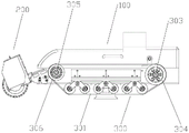
As shown in fig. 1 to 14: for the embodiment of the utility model provides a photovoltaic cleaning robot that can return journey and continuation of journey automatically, photovoltaic cleaning robot includes automobile body 100, the clean subassembly 200 of round brush and track drive arrangement 300, the clean subassembly 200 of round brush sets up the front side of automobile body 100, photovoltaic cleaning robot passes through the clean subassembly 200 of round brush carries out cleaning operation to the photovoltaic board, track drive arrangement 300 sets up the both sides of automobile body 100, photovoltaic cleaning robot is in walk under the drive of track drive arrangement 300, automobile body 100 includes chassis (not shown in the figure) and sets up frame 101 on the chassis, be provided with casing 103 on frame 101, the left side wall and the right side wall outside of frame 101 are provided with one respectively track drive arrangement 300, be provided with ultrasonic module 104, camera module 105 on the chassis, A battery module 106 and a micro control unit (not shown in the figure), the ultrasonic module 104, the camera module 105 and the battery module 106 being electrically connected to the micro control unit respectively, wherein:
the micro control unit scores the overall state of the photovoltaic cleaning robot by sensing the electric quantity of the battery module 106, the slip rate of the crawler driving device 300 and the ultrasonic data sent by the ultrasonic module 104, records the abnormal reason and triggers a return flight instruction if the abnormal reason occurs for a period of time; the micro control unit calculates a nearest path for return voyage according to the current operation state of the photovoltaic cleaning robot and the path planning data through a decision system; when the fault is solved, the photovoltaic cleaning robot is placed at the initial point again, the starting equipment is initialized, the micro control unit judges scene similarity and the last operation state according to the operation record to determine whether the breakpoint cruising function needs to be started, if the breakpoint cruising function is started, the number of lines which are not operated before cruising return is analyzed according to the operation record, and the micro control unit controls the photovoltaic cleaning robot to reach the designated position to perform continuous operation.
The micro control unit senses the electric quantity of the battery module 106, and specifically includes: the micro control unit performs partial pressure sampling on the bus voltage in real time through the double resistors, transmits the acquired voltage signal to an analog-to-digital converter (ADC) interface in the micro control unit, and optimizes and converts the voltage signal through software, so that the accuracy of measuring the electric quantity of the battery module 106 is ensured. For example, when the electric quantity of the battery module 106 is 25V, the voltage acquired by the ADC is 3.16V, and the electric quantity of the battery module 106 is sufficient; when the electric quantity of the battery module 106 is 15V, the voltage collected by the ADC is 1.896V. During the autonomous operation of the photovoltaic cleaning robot, the voltage collected by the ADC is lower than 1.896V, and maintaining the state for more than 2s triggers an abnormal alarm of insufficient battery of the battery module 106.
The crawler driving device 300 is provided with an encoder, and the encoder is used for feeding back the speed of a crawler 301 in the crawler driving device 300 so as to obtain a driving mileage; acquiring visual mileage of the photovoltaic cleaning robot through the camera module 105; the vehicle body 100 is further provided with an inertia measurement unit (not shown in the figure), the inertia mileage of the photovoltaic cleaning robot is obtained through the inertia measurement unit, and then the state of the crawler driving device 300 is judged to be good within the same reasonable range through the driving mileage, the visual mileage and the inertia mileage.
When the deviation between the driving range, the visual range and the inertia range is large, the slip rate of the crawler driving device 300 is high at this time, and if the state is maintained for more than a certain time, for example, 2s, an abnormal alarm of the slip rate being high is triggered.
By monitoring the ultrasonic data sent by the ultrasonic module 104, when the photovoltaic cleaning robot is in the cleaning process, the ultrasonic data exceeds the floating range between the vehicle body 100 and the surface of the photovoltaic panel for a long time, and if the state is maintained for a certain time, an ultrasonic data abnormal alarm is triggered. Specifically, when the photovoltaic cleaning robot normally works on the photovoltaic surface, the ultrasonic data is 30-50mm, if a foreign matter is always adhered to the surface of the ultrasonic transmission module 104 at the moment, the data obtained by shielding the normal work of the photovoltaic cleaning robot is 0mm, and other ultrasonic modules 104 are normally in the range of 30-50mm, the state is maintained for more than 2 seconds, and the ultrasonic data abnormal alarm is triggered.
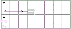
The vehicle body 100 is provided with a monitoring system, and when the monitoring system receives the abnormal alarm of the high slip rate and/or the abnormal alarm of the ultrasonic data, the monitoring system informs the decision system and records the current abnormal reason, and triggers a return flight instruction. The operation mode of the photovoltaic cleaning robot is that the lower end of a photovoltaic array is used as a starting point, the first stage of the photovoltaic cleaning robot drives to the last row of assemblies of the photovoltaic array in a straight line mode, then the second stage of the photovoltaic cleaning robot starts to operate in a transverse mode until the photovoltaic array is completely covered, therefore, a return route can be determined according to the operation state of the photovoltaic cleaning robot and the scene of the photovoltaic array, and if the photovoltaic cleaning robot drives to the last row of photovoltaic array in the straight line mode, the photovoltaic cleaning robot immediately turns around and returns to the back; if the transverse operation is started to enter the second stage, at the moment, the direction of the photovoltaic cleaning robot is the same as the operation direction of the photovoltaic array, the robot continues to advance until the robot starts to turn around to return to the path of the first stage when the robot travels to a safe distance allowing turning around, then turns around to the position of the starting point, and the robot can travel to the starting point in a straight line; and if the transverse operation is started to enter the second stage, at the moment, the photovoltaic cleaning robot continues to run to the path where the edge of the photovoltaic array reaches the first stage when the direction of the photovoltaic cleaning robot is opposite to the direction of the array operation, then the turning of the next line of operation is cancelled, the turning direction is towards the position of the starting point, and the linear operation is only required to be carried out to the starting point.
When the working personnel solve the problems of insufficient battery capacity, high slip rate of a driving device or abnormal ultrasonic data, the equipment is placed below the array to continue operation, the equipment normally finishes the first-order straight-line driving to the last line of assemblies of the array, and normal autonomous operation of the cruising function is cancelled by judging whether the scene and the operation direction are the same as the operation record or not and if the scene is different. If the scenes are the same and the number of the cleaning lines is more than 2, starting a cruising function, and if the equipment operation records are in a first odd number line for returning to the navigation, directly returning to the starting point of the line, and then starting autonomous transverse operation; if the device job record is performed on the even-numbered row, the job is performed from the next row, that is, the autonomous horizontal job is started on the row number of the current even-numbered row plus one.
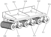
The crawler driving module 300 comprises a crawler 301, and a driving module, a driven module, a pressure bearing frame 302 and a pressing module which are arranged in the crawler 301, wherein the driven module and the driving module are respectively arranged at the front end and the rear end in the crawler 301, one side of the pressure bearing frame 302 is fixedly connected with the outer side wall of the frame 101, and the pressing module is movably arranged below the pressure bearing frame 302.
The driving module comprises a driving shaft 303 and a driving wheel 304 fixedly arranged on the driving shaft 303, wherein the driving shaft 303 is driven by a driving motor (not shown in the figure) arranged on the frame 101 to rotate, and the driving wheel 304 drives the crawler 301 to move. In addition, a locknut 307 is provided at one end of the driving shaft 303, which is located at the driving wheel 304, so as to limit the orientation of the driving wheel 304, prevent the driving wheel 304 from being separated from the driving shaft 303, and improve the safety and reliability to a certain extent.
The driven module comprises a driven shaft 305 and a driven wheel 306 arranged on the driven shaft 305, wherein a locknut 307 is arranged at one end, located on the driven wheel 306, of the driven shaft 305, so that the driven wheel 306 can be effectively prevented from falling off from the driven shaft 305, and the safety and reliability are further improved.
The pressure bearing frame 302 comprises a first pressure bearing plate 321 and a second pressure bearing plate 322, the first pressure bearing plate 321 is vertically arranged along the length direction and is fixedly arranged on the outer side wall of the frame 101 through a fastening bolt (not shown in the figure), the second bearing plate 322 is horizontally disposed along the length direction and a sidewall along the length direction is fixedly connected to the lower end of the first bearing plate 321, a plurality of groups of fixing parts are arranged on the lower surface of the second bearing plate 322 along the length direction, a support fixing beam 308 is arranged in each group of fixing parts, the two ends of the bracket fixing beam 308 are respectively provided with a pinch roller outer bracket 309 and a pinch roller inner bracket 310, a pinch roller fixing shaft 311 is arranged between the pinch roller outer support 309 and the pinch roller inner support 310, two ends of the pinch roller fixing shaft 311 are provided with pinch rollers 313 through bearings 312, and the pinch rollers 313 abut against arc-shaped teeth arranged on the inner side wall of the crawler 301. Meanwhile, the bracket fixing beam 308, the pinch roller outer bracket 309, the pinch roller inner bracket 310, the pinch roller fixing shaft 311 and the pinch roller 313 form the pinch module. The pinch roller 313, the drive roller 304, and the driven roller 306 are engaged with arc-shaped teeth provided on the inner wall of the crawler 301.
First bearing plate 321 with second bearing plate 322 is integrated into one piece, the upper surface of second bearing plate 322 is provided with a plurality of strengthening ribs 320 along length direction, the one end of strengthening rib 320 with the lateral wall fixed connection of first bearing plate 321. Through the above design, that is, the first bearing plate 321 and the second bearing plate 322 are integrally formed, so that the firmness of the combination of the first bearing plate 321 and the second bearing plate 322 can be improved, and the safety and reliability are improved; in addition, the plurality of reinforcing ribs 320 are arranged on the second bearing plate 322, so that the strength of the second bearing plate 322 can be further improved, and the purpose of prolonging the service life of the bearing frame 302 is further achieved.
Each set of fixing portions includes a first fixing protrusion 331 and a second fixing protrusion 332, a first fixing hole 333 is provided in the first fixing protrusion 331, a second fixing hole 334 is provided in the second fixing protrusion 332, and two ends of the bracket fixing beam 308 are respectively disposed in the first fixing hole 333 and the second fixing hole 334. Meanwhile, the first fixing protrusion 331 is fixedly disposed at a front end of a lower surface of the second bearing plate 322, and the second fixing protrusion 332 is fixedly disposed at a rear end of the lower surface of the second bearing plate 322. In addition, the first fixing protrusion 331 may be formed by extending the front end of the first bearing plate 322 downward, so that the firmness of the combination of the first fixing protrusion 331 and the second bearing plate 322 may be improved, and the safety and reliability may be further improved.
The outer pinch roller support 309 and the inner pinch roller support 310 both comprise installation portions 314, a first connecting plate 315 and a second connecting plate 316 are arranged on the left side and the right side of the installation portions 314 respectively, the first connecting plate 315, the second connecting plate 316 and the installation portions 314 form an inverted V-shaped structure, the end portions of the support fixing beams 308 are arranged in installation holes 317 in the installation portions 314, a first connecting hole 318 is formed in one end, far away from the installation portions 314, of the first connecting plate 315, a pinch roller fixing shaft 311 is arranged in the first connecting hole 318, a second connecting hole 319 is formed in one end, far away from the installation portions 314, of the second connecting plate 316, and the pinch roller fixing shaft 311 is arranged in the second connecting hole 319.
Through the above design, that is, the outer pinch roller support 309 and the inner pinch roller support 310 both include the mounting portion 314, and the left side and the right side of the mounting portion 314 are respectively provided with the first connecting plate 315 and the second connecting plate 316 in an outward extending manner, that is, the first connecting plate 315 and the second connecting plate 316 are integrally formed with the mounting portion 314, so that the combining firmness of the first connecting plate 315 and the second connecting plate 316 with the mounting portion 314 can be improved; since the mounting portion 314 is provided therein with the mounting hole 317, both ends of the bracket fixing beam 308 are respectively provided in the mounting hole 317 of the mounting portion 314 in the pinch roller outer bracket 309 and the mounting hole 317 of the mounting portion 314 in the pinch roller inner bracket 310, so that the pinch roller outer bracket 309 and the pinch roller inner bracket 310 are connected to the second pressure bearing plate 322 through the bracket fixing beam 308.
In addition, because the structure formed by the first connecting plate 315, the second connecting plate 316 and the mounting portion 314 is an inverted V-shaped structure, the firmness of the combination of the first connecting plate 315, the second connecting plate 316 and the mounting portion 314 can be further improved; meanwhile, an end of the first connection plate 315 remote from the mounting portion 314, that is, a tip of the first connection plate 315 is provided with a first connection hole 318, and an end of the second connection plate 316 remote from the mounting portion 314 i.e. a tip end of the second connection plate 316 is provided with a second connection hole 319, the pinch roller fixing shaft 311 is disposed between the two corresponding first coupling holes 318 and the two corresponding second coupling holes 319 between the pinch roller outer frame 309 and the pinch roller inner frame 310, and the two ends of the pinch roller fixing shaft 311 are respectively provided with pinch rollers 313 through bearings 312, that is, the second supporting plate 322 is movably connected with the plurality of pinch rollers 313 through the pinch roller outer bracket 309 and the pinch roller inner bracket 310, the pressure-bearing frame 302 abuts against the inner side wall of the crawler 301 through a plurality of pressure rollers 313 arranged in parallel to each other, so that the crawler 301 is in close contact with the working surface, i.e., the surface of the photovoltaic panel.
The embodiment of the utility model provides a photovoltaic cleaning robot that can return journey and continue journey automatically, when the electric quantity stage of the battery module of photovoltaic cleaning robot is low, the slip rate stage of track drive arrangement is higher and the ultrasonic data stage that the ultrasonic module sent is unusual, above-mentioned little control unit record unusual reason and return journey independently; meanwhile, the micro control unit calculates the nearest path for return voyage according to the current equipment operation state and the path planning data through a decision system; and after the fault is solved, the photovoltaic cleaning robot is placed at the initial point again, and the starting equipment is initialized to judge that the operation is continued according to the return journey record and the analysis of the number of rows of the non-operation of the return journey and the return journey belongs to the same scene.
Finally, it should be noted that: the above-mentioned embodiments are only used for illustrating the technical solution of the present invention, and not for limiting the same; although the present invention has been described in detail with reference to the foregoing embodiments, it should be understood by those skilled in the art that: the technical solutions described in the foregoing embodiments may still be modified, or some or all of the technical features may be equivalently replaced; such modifications and substitutions do not depart from the spirit and scope of the present invention.
Claims (8)
1. The utility model provides a photovoltaic cleaning robot that can return journey and continuation of journey automatically, photovoltaic cleaning robot includes automobile body, the clean subassembly of round brush and track drive arrangement, the clean subassembly setting of round brush is in the front side of automobile body, photovoltaic cleaning robot passes through the clean subassembly of round brush carries out cleaning operation to the photovoltaic board, track drive arrangement sets up the both sides of automobile body, photovoltaic cleaning robot is in walk its characterized in that under track drive arrangement's the drive: the automobile body includes the chassis and sets up frame on the chassis, be provided with the casing on the frame, the left side wall and the right side wall outside of frame are provided with one respectively track drive arrangement, be provided with ultrasonic module, camera module, battery module and little the control unit on the chassis, ultrasonic module, camera module and battery module respectively with little the control unit electricity is connected, wherein: the micro control unit senses the electric quantity of the battery module, the slip rate of the crawler driving device and ultrasonic data sent by the ultrasonic module.
2. The photovoltaic cleaning robot capable of automatically returning and continuing to sail according to claim 1, wherein an encoder is arranged on the track driving device and used for feeding back the speed of a track in the track driving device to obtain a driving mileage;
acquiring the visual mileage of the photovoltaic cleaning robot through the camera module;
the vehicle body is further provided with an inertia measuring unit, and the inertia mileage of the photovoltaic cleaning robot is obtained through the inertia measuring unit.
3. The photovoltaic cleaning robot capable of automatically returning and continuing to drive according to claim 2, wherein when the deviation between the driving mileage, the visual mileage and the inertial mileage is large, the slip rate of the crawler driving device is high, and when the slip rate is high and exceeds a certain time, an abnormal alarm of the slip rate being high is triggered.
4. The photovoltaic cleaning robot capable of automatic returning and resuming driving of claim 3, wherein the ultrasonic data sent by the ultrasonic module is monitored, and when the photovoltaic cleaning robot is in a cleaning operation process, the ultrasonic data exceeds a floating range between the vehicle body and the surface of the photovoltaic panel for a long time, and an ultrasonic data abnormal alarm is triggered after a certain time.
5. The photovoltaic cleaning robot capable of automatically returning and continuing voyage according to any one of claims 1 to 3, wherein the track driving device comprises a track, and a driving module, a driven module, a pressure-bearing frame and a pressing module which are arranged inside the track, the driven module and the driving module are respectively arranged at the front end and the rear end of the track, one side of the pressure-bearing frame is fixedly connected with the outer side wall of the frame, and the pressing module is movably arranged below the pressure-bearing frame.
6. The photovoltaic cleaning robot capable of automatic returning and endurance according to claim 5, wherein the driving module comprises a driving shaft and a driving wheel fixedly arranged on the driving shaft, the driving shaft is driven by a driving motor arranged on the frame to rotate, and the driving wheel drives the track to move.
7. The photovoltaic cleaning robot capable of automatic returning and endurance according to claim 5, wherein the driven module comprises a driven shaft and a driven wheel arranged on the driven shaft, and a locknut is arranged at one end of the driven shaft, which is located at the driven wheel.
8. The photovoltaic cleaning robot capable of automatically returning and continuing to sail according to claim 5, wherein the pressure bearing frame comprises a first pressure bearing plate and a second pressure bearing plate, the first pressure bearing plate is vertically arranged along a length direction and fixedly arranged on an outer side wall of the frame through a fastening bolt, the second pressure bearing plate is horizontally arranged along the length direction and fixedly connected with a lower end of the first pressure bearing plate along a side wall of the length direction, and a plurality of groups of fixing portions are arranged on a lower surface of the second pressure bearing plate along the length direction.
Priority Applications (1)
| Application Number | Priority Date | Filing Date | Title |
|---|---|---|---|
| CN202120934379.9U CN214918506U (en) | 2021-05-03 | 2021-05-03 | Photovoltaic cleaning robot capable of automatically returning and continuing to sail |
Applications Claiming Priority (1)
| Application Number | Priority Date | Filing Date | Title |
|---|---|---|---|
| CN202120934379.9U CN214918506U (en) | 2021-05-03 | 2021-05-03 | Photovoltaic cleaning robot capable of automatically returning and continuing to sail |
Publications (1)
| Publication Number | Publication Date |
|---|---|
| CN214918506U true CN214918506U (en) | 2021-11-30 |
Family
ID=79065766
Family Applications (1)
| Application Number | Title | Priority Date | Filing Date |
|---|---|---|---|
| CN202120934379.9U Active CN214918506U (en) | 2021-05-03 | 2021-05-03 | Photovoltaic cleaning robot capable of automatically returning and continuing to sail |
Country Status (1)
| Country | Link |
|---|---|
| CN (1) | CN214918506U (en) |
Cited By (2)
| Publication number | Priority date | Publication date | Assignee | Title |
|---|---|---|---|---|
| CN113198765A (en) * | 2021-05-03 | 2021-08-03 | 深圳怪虫机器人有限公司 | Photovoltaic cleaning robot capable of automatically returning and continuing to sail |
| CN114932107A (en) * | 2022-04-27 | 2022-08-23 | 浙江大学湖州研究院 | Device for cleaning solar photovoltaic panel |
-
2021
- 2021-05-03 CN CN202120934379.9U patent/CN214918506U/en active Active
Cited By (2)
| Publication number | Priority date | Publication date | Assignee | Title |
|---|---|---|---|---|
| CN113198765A (en) * | 2021-05-03 | 2021-08-03 | 深圳怪虫机器人有限公司 | Photovoltaic cleaning robot capable of automatically returning and continuing to sail |
| CN114932107A (en) * | 2022-04-27 | 2022-08-23 | 浙江大学湖州研究院 | Device for cleaning solar photovoltaic panel |
Similar Documents
| Publication | Publication Date | Title |
|---|---|---|
| CN214918506U (en) | Photovoltaic cleaning robot capable of automatically returning and continuing to sail | |
| CN204810230U (en) | Detect system for among photovoltaic module fault detection | |
| CN105680789A (en) | Automatic cleaning system for solar cell panel | |
| WO2022267336A1 (en) | Photovoltaic cleaning robot based on visual slam | |
| CN105703703A (en) | Automatic cleaning device for solar cell panel | |
| CN214315184U (en) | Photovoltaic power plant cleaning machines people | |
| CN113198765A (en) | Photovoltaic cleaning robot capable of automatically returning and continuing to sail | |
| CN114362286A (en) | Charging system and method on overhead transmission line inspection robot tower | |
| CN108111118B (en) | Photovoltaic module cleaning robot and control method thereof | |
| CN111452815B (en) | Fault rescue traction system of photovoltaic module cleaning robot | |
| CN110000816B (en) | Novel charging method for inspection robot | |
| CN114918211A (en) | Heliostat cleaning device and cleaning method | |
| CN209774710U (en) | Novel battery charging outfit of inspection robot | |
| CN113263002A (en) | Method for continuous operation of photovoltaic cleaning robot across photovoltaic array | |
| CN109382346B (en) | Control method of intelligent absorbing and storing system of solar cell panel | |
| CN115338163B (en) | Automatic photovoltaic system who cleans | |
| CN219235310U (en) | Intelligent inspection robot with recognition function | |
| CN217532596U (en) | Charging pile | |
| CN216460346U (en) | Photovoltaic cleaning robot based on vision SLAM | |
| CN217869969U (en) | Modular bridge detection vehicle frame | |
| CN212875734U (en) | Solar photovoltaic power generation board cleaning vehicle | |
| CN218082725U (en) | Photovoltaic board cleans equipment | |
| CN220383014U (en) | Photovoltaic cleaning robot with deviation correcting function | |
| CN217100258U (en) | Omnidirectional mobile robot based on independent suspension damping device | |
| CN220122646U (en) | Charging device and inspection robot charging system |
Legal Events
| Date | Code | Title | Description |
|---|---|---|---|
| GR01 | Patent grant | ||
| GR01 | Patent grant |