CN214887186U - Colliery is air door blocking device in pit - Google Patents
Colliery is air door blocking device in pit Download PDFInfo
- Publication number
- CN214887186U CN214887186U CN202121398410.8U CN202121398410U CN214887186U CN 214887186 U CN214887186 U CN 214887186U CN 202121398410 U CN202121398410 U CN 202121398410U CN 214887186 U CN214887186 U CN 214887186U
- Authority
- CN
- China
- Prior art keywords
- air door
- wall
- mounting panel
- controller
- pipe
- Prior art date
- Legal status (The legal status is an assumption and is not a legal conclusion. Google has not performed a legal analysis and makes no representation as to the accuracy of the status listed.)
- Active
Links
- 230000000903 blocking effect Effects 0.000 title claims abstract description 6
- 230000000670 limiting effect Effects 0.000 claims abstract description 29
- 230000007246 mechanism Effects 0.000 claims abstract description 14
- 239000002184 metal Substances 0.000 claims abstract description 14
- 238000003466 welding Methods 0.000 claims abstract description 6
- 229910000831 Steel Inorganic materials 0.000 claims description 21
- 239000010959 steel Substances 0.000 claims description 21
- 239000003245 coal Substances 0.000 claims description 10
- 230000001681 protective effect Effects 0.000 claims description 4
- 230000035939 shock Effects 0.000 claims description 3
- 238000010521 absorption reaction Methods 0.000 claims description 2
- 230000007659 motor function Effects 0.000 abstract 1
- 238000005096 rolling process Methods 0.000 abstract 1
- 230000009471 action Effects 0.000 description 2
- 230000000694 effects Effects 0.000 description 2
- 230000004888 barrier function Effects 0.000 description 1
- 230000008859 change Effects 0.000 description 1
- 230000007547 defect Effects 0.000 description 1
- 230000005484 gravity Effects 0.000 description 1
- 238000009434 installation Methods 0.000 description 1
Images


Abstract
The utility model discloses a colliery is wind door blocking device in pit, including blocked mechanical system, stop gear, adjustment mechanism, controller, blocked mechanical system includes the mounting panel, install in left air door pipe and right air door pipe of mounting panel one side outer wall bottom, weld in two mounting brackets of left air door pipe, right air door pipe and mounting panel junction, sliding connection in the bar metal of left air door pipe and right air door inside pipe wall, stop gear is including welding in the cable wire at two bar metal tops, welding in the spacing ring of cable wire one side outer wall, weld in the limiting plate of mounting panel one side outer wall. The utility model discloses a set up a servo motor respectively in mounting panel both sides, when needing to open arbitrary one air door, only need through the servo motor function that controller control corresponds, can drive and receive the line gyro wheel and rotate, receive the line gyro wheel and rotate and can be with the cable wire rolling, the cable wire drives the stick of metal and rises, when the spacing ring that the cable wire outer wall set up contacted limiting plate bottom outer wall, made the air door open easy operation.
Description
Technical Field
The utility model relates to a colliery field especially relates to a colliery is wind door blocking device in pit.
Background
The action principle of a manual non-pressure air door locking device is as follows: the two air doors are respectively connected with a counterweight barrel through steel wire ropes, the counterweight barrels apply pulling/pressure to the air doors through the guide wheels under the action of gravity, namely, the air doors can realize the natural closing function after being manually opened. Under normal conditions, when a person (vehicle) needing to pass through a first air door and then opens a second air door after the first air door is closed, but when the locking device fails and two opposite persons (vehicles) open the air doors simultaneously, the air door locking device cannot effectively play a role in interlocking the air doors, and the stability of underground airflow can be influenced by simultaneously opening the two air doors;
the existing underground air door locking device mostly needs to manually pull the steel cable to open the air door, the physical consumption of operators is large, the steel cable scratches the palm of the operators easily, and the existing underground air door locking device is too simple in limiting structure and poor in limiting effect on a metal bar through an inverted triangle.
SUMMERY OF THE UTILITY MODEL
The utility model aims at solving the defects existing in the prior art and providing a coal mine underground air door locking device.
In order to achieve the above purpose, the utility model adopts the following technical scheme:
a coal mine underground air door locking device comprises a locking mechanism, a limiting mechanism, an adjusting mechanism and a controller, the locking mechanism comprises a mounting plate, a left air door pipe and a right air door pipe which are arranged at the bottom of the outer wall at one side of the mounting plate, two mounting frames which are welded at the joint of the left air door pipe, the right air door pipe and the mounting plate, and a metal bar which is connected with the inner walls of the left air door pipe and the right air door pipe in a sliding way, the limiting mechanism comprises a steel cable welded at the tops of two metal rods, a limiting ring welded on the outer wall of one side of the steel cable, a limiting plate welded on the outer wall of one side of the mounting plate and a pressure sensor arranged at the top of the limiting ring, the adjusting mechanism comprises two bearings welded on the outer wall of one side of the mounting plate, a pulley welded at one end of the bearing, a servo motor arranged on the outer walls of two sides of the mounting plate and a take-up roller sleeved at the output end of the servo motor, and the pressure sensor is connected to the input end of the controller through a signal line.
Preferably, two sliding holes are formed in the top of the limiting plate, the sliding holes and the steel cable form sliding fit, the steel cable is sleeved on the outer wall of one side of the two take-up rollers respectively, and the steel cable and the outer wall of the pulley form sliding fit.
Preferably, the bottom of the servo motor is welded with a fixing support, and the fixing support is welded on the outer wall of one side of the mounting plate.
Preferably, the outer wall welding of mounting panel one side has the guardrail bar, and the soft cover of antiskid has been cup jointed to the guardrail bar outer wall.
Preferably, the controller is welded on the outer wall of one side of the mounting plate, and a shock absorption gasket is sleeved at the joint of the controller and the mounting plate.
Preferably, the servo motor is connected to the output end of the controller through a wire, and the controller is connected to a power line.
The utility model has the advantages that:
1. the servo motors are respectively arranged on the two sides of the mounting plate, when any one air door needs to be opened, the controller is only needed to control the corresponding servo motor to operate, the take-up roller can be driven to rotate, the take-up roller can rotate to wind the steel cable, the steel cable drives the metal rod to ascend, when the limiting ring arranged on the outer wall of the steel cable contacts the outer wall of the bottom of the limiting plate, the air door is opened, one-key operation is realized, the operation is simple, the physical consumption of operators can be greatly reduced, the operators can avoid direct contact with the device, the safety is improved, the speed of opening the air door can be increased, and the working efficiency is improved;
2. set up pressure sensor at the spacing ring top through the setting, when the spacing ring contacted the limiting plate, can make pressure sensor carry to the controller with the pressure signal who senses, the servo motor stop work can be controlled to the controller, realize automatic spacing, spacing effect is better for traditional set-square that falls, the steadiness is higher, and can end automatically and stop, avoid operating personnel contact device, and can protect equipment through the guard rail who sets up at mounting panel one side outer wall, avoid operating personnel contact device to cause the unnecessary damage.
Drawings
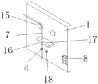
Fig. 1 is a front perspective view of the locking device for the underground coal mine air door according to the present invention.
Fig. 2 is a schematic rear-view three-dimensional structure view of the coal mine underground air door locking device provided by the utility model;
fig. 3 is the utility model provides a colliery is air door blocking device stop gear's spatial structure sketch map in pit.
In the figure: the device comprises a mounting plate 1, an adjusting mechanism 2, a pulley 3, a limiting ring 4, a left air door pipe 5, a metal bar 6, a steel cable 7, a controller 8, a protective railing 9, a right air door pipe 10, an installation frame 11, a fixed support 12, a servo motor 13, a take-up roller 14, a bearing 15, a limiting plate 16, a sliding hole 17 and a pressure sensor 18.
Detailed Description
The technical solutions in the embodiments of the present invention will be described clearly and completely with reference to the accompanying drawings in the embodiments of the present invention, and it is obvious that the described embodiments are only some embodiments of the present invention, not all embodiments.
Referring to fig. 1-3, a coal mine underground air door locking device comprises a mounting plate 1, an adjusting mechanism 2, a pulley 3, a limiting ring 4, a left air door pipe 5, a metal rod 6, a steel cable 7, a controller 8, a guard rail 9, a right air door pipe 10, a mounting frame 11, a fixing support 12, a servo motor 13, a take-up roller 14, a bearing 15, a limiting plate 16, a sliding hole 17 and a pressure sensor 18, wherein the locking mechanism comprises the mounting plate 1, the left air door pipe 5 and the right air door pipe 10 which are mounted at the bottom of the outer wall on one side of the mounting plate 1, two mounting frames 11 which are welded at the joint of the left air door pipe 5 and the right air door pipe 10, the metal rod 6 which is slidably connected with the inner walls of the left air door pipe 5 and the right air door pipe 10, the limiting mechanism comprises the steel cable 7 which is welded at the tops of the two metal rods 6, the limiting ring 4 which is welded at the outer wall on one side of the steel cable 7, the limiting plate 16 and the pressure sensor 18 which is mounted at the top of the outer wall on one side of the mounting plate 1, the adjusting mechanism 2 comprises two bearings 15 welded on the outer wall of one side of the mounting plate 1, a pulley 3 welded on one end of the bearing 15, servo motors 13 arranged on the outer walls of two sides of the mounting plate 1 and take-up rollers 14 sleeved on the output ends of the servo motors 13, and the pressure sensor 18 is connected to the input end of the controller 8 through a signal line;
two sliding holes 17 have been seted up at the 16 tops of limiting plate, and sliding holes 17 form sliding fit, two with cable wire 7 cup joints respectively in two receipts line gyro wheel 14 one side outer walls, cable wire 7 forms sliding fit with 3 outer walls of pulley, the welding of servo motor 13 bottom has fixed bolster 12, and fixed bolster 12 welds in mounting panel 1 one side outer wall, the welding of mounting panel 1 one side outer wall has guardrail bar 9, and guardrail bar 9 outer wall has cup jointed anti-skidding flexible sleeve, controller 8 welds in mounting panel 1 one side outer wall, and controller 8 has cup jointed shock attenuation gasket with mounting panel 1 junction, servo motor 13 passes through the wire and connects in 8 outputs of controller, and 8 line connections of controller.
The working principle is as follows: by arranging the servo motors 13 on two sides of the mounting plate 1 respectively, when any one air door needs to be opened, the controller 8 is only needed to control the corresponding servo motor 13 to operate, the take-up roller 14 can be driven to rotate, the take-up roller 14 can rotate to wind the steel cable 7, the steel cable 7 drives the metal rod 6 to ascend, when the limiting ring 4 arranged on the outer wall of the steel cable 7 contacts the outer wall of the bottom of the limiting plate 16, the air door is opened, one-key operation is realized, the operation is simple, the physical consumption of operators can be greatly reduced, the operators can avoid direct contact with devices, the safety is improved, the speed of opening the air door can be increased, the working efficiency is improved, by arranging the pressure sensor 18 on the top of the limiting ring 4, when the limiting ring 4 contacts the limiting plate 16, the pressure sensor 18 can transmit the sensed pressure signal to the controller 8, and the controller 8 can control the servo motor 13 to stop operating, realize automatic spacing, it is better for the spacing effect of traditional set square that falls, the steadiness is higher, and can end automatically and stop, avoid operating personnel contact device, and can protect equipment through setting up at the protective barrier 9 of 1 one side outer wall of mounting panel, avoid operating personnel contact device to cause the unnecessary damage.
In the description of the present invention, it is to be understood that the terms "center", "longitudinal", "lateral", "length", "width", "thickness", "upper", "lower", "front", "rear", "left", "right", "vertical", "horizontal", "top", "bottom", "inner", "outer", "clockwise", "counterclockwise", and the like indicate orientations or positional relationships based on the orientations or positional relationships shown in the drawings, and are only for convenience of description and to simplify the description, but do not indicate or imply that the device or element referred to must have a particular orientation, be constructed and operated in a particular orientation, and therefore should not be construed as limiting the present invention.
Furthermore, the terms "first", "second" and "first" are used for descriptive purposes only and are not to be construed as indicating or implying relative importance or implicitly indicating the number of technical features indicated. Thus, a feature defined as "first" or "second" may explicitly or implicitly include one or more of that feature. In the description of the present invention, "a plurality" means two or more unless specifically limited otherwise.
The above, only be the concrete implementation of the preferred embodiment of the present invention, but the protection scope of the present invention is not limited thereto, and any person skilled in the art is in the technical scope of the present invention, according to the technical solution of the present invention and the utility model, the concept of which is equivalent to replace or change, should be covered within the protection scope of the present invention.
Claims (6)
1. The utility model provides a colliery is air door blocking device in pit, includes latched device, stop gear, adjustment mechanism (2), controller (8), a serial communication port, latched device includes mounting panel (1), install in left air door pipe (5) and right air door pipe (10) of mounting panel (1) one side outer wall bottom, weld in two mounting bracket (11) of left air door pipe (5), right air door pipe (10) and mounting panel (1) junction, sliding connection in metal rod (6) of left air door pipe (5) and right air door pipe (10) inner wall, stop gear is including welding in cable wire (7) at two metal rod (6) tops, weld in spacing ring (4) of cable wire (7) one side outer wall, weld in limiting plate (16) of mounting panel (1) one side outer wall and install in pressure sensor (18) at spacing ring (4) top, adjustment mechanism (2) include two bearings (15) of mounting panel (1) one side outer wall, Weld pulley (3), install in servo motor (13) of mounting panel (1) both sides outer wall and cup joint in receiving line gyro wheel (14) of servo motor (13) output of bearing (15) one end, pressure sensor (18) are connected in controller (8) input through signal line.
2. The coal mine underground air door locking device according to claim 1, wherein two sliding holes (17) are formed in the top of the limiting plate (16), the sliding holes (17) are in sliding fit with the steel cable (7), the two steel cables (7) are respectively sleeved on the outer wall of one side of the two take-up rollers (14), and the steel cable (7) is in sliding fit with the outer wall of the pulley (3).
3. The coal mine underground air door locking device according to claim 1, characterized in that a fixing support (12) is welded at the bottom of the servo motor (13), and the fixing support (12) is welded on the outer wall of one side of the mounting plate (1).
4. The coal mine underground air door locking device according to claim 1, characterized in that a protective railing (9) is welded on the outer wall of one side of the mounting plate (1), and an anti-skid soft sleeve is sleeved on the outer wall of the protective railing (9).
5. The coal mine underground air door locking device according to claim 1, characterized in that the controller (8) is welded on the outer wall of one side of the mounting plate (1), and a shock absorption gasket is sleeved at the joint of the controller (8) and the mounting plate (1).
6. The coal mine underground air door locking device according to claim 1, characterized in that the servo motor (13) is connected to the output end of the controller (8) through a wire, and the controller (8) is connected with a power line.
Priority Applications (1)
| Application Number | Priority Date | Filing Date | Title |
|---|---|---|---|
| CN202121398410.8U CN214887186U (en) | 2021-06-23 | 2021-06-23 | Colliery is air door blocking device in pit |
Applications Claiming Priority (1)
| Application Number | Priority Date | Filing Date | Title |
|---|---|---|---|
| CN202121398410.8U CN214887186U (en) | 2021-06-23 | 2021-06-23 | Colliery is air door blocking device in pit |
Publications (1)
| Publication Number | Publication Date |
|---|---|
| CN214887186U true CN214887186U (en) | 2021-11-26 |
Family
ID=78930027
Family Applications (1)
| Application Number | Title | Priority Date | Filing Date |
|---|---|---|---|
| CN202121398410.8U Active CN214887186U (en) | 2021-06-23 | 2021-06-23 | Colliery is air door blocking device in pit |
Country Status (1)
| Country | Link |
|---|---|
| CN (1) | CN214887186U (en) |
-
2021
- 2021-06-23 CN CN202121398410.8U patent/CN214887186U/en active Active
Similar Documents
| Publication | Publication Date | Title |
|---|---|---|
| JP5827347B2 (en) | Electric vehicle platform safety device | |
| CN111021643B (en) | Snow removing equipment for pitched roof | |
| CN214887186U (en) | Colliery is air door blocking device in pit | |
| CN206625761U (en) | A kind of shield door compound ventilation air-changing device | |
| CN211176193U (en) | Teaching device for multimedia classroom | |
| CN107522075A (en) | A kind of automatic opening-closing for construction elevator door | |
| CN215402697U (en) | Trackless rubber-tyred single-double speed electric hoist gantry crane | |
| CN108979225B (en) | Double-deck parking equipment | |
| CN107188013B (en) | Cage door for mine lifting | |
| KR100873175B1 (en) | Parking apparatus | |
| CN213964917U (en) | Lifting emergency main fighting fire truck | |
| CN209838059U (en) | Special vertical hinged door for lifting opening | |
| CN208472681U (en) | Surface low road movable overhaul platform in a kind of power station | |
| CN113562576A (en) | Energy-saving cargo elevator | |
| CN216002600U (en) | Roadster protecting device for inclined roadway | |
| CN204827513U (en) | Roll up curtain formula unloading chamber anti -falling device | |
| CN201002929Y (en) | Small-sized road maintenance machinery hoisting transporting vehicle | |
| CN216157110U (en) | Higher sliding bracket of construction usefulness of security | |
| CN217579810U (en) | A portable assembled hangs basket device for bridge maintenance construction | |
| CN215592498U (en) | Vertical transportation device for chimney cooling tower construction | |
| CN218434787U (en) | Tower crane overhauls hangs basket convenient to adjust | |
| CN212163912U (en) | Monitoring device for traffic electromechanical equipment | |
| CN108149641A (en) | A kind of tilting blocks drift system and blocks bleaching method | |
| CN219753914U (en) | Hanging basket with quick locking structure | |
| CN219687320U (en) | Mining inclined roadway truck-trailer |
Legal Events
| Date | Code | Title | Description |
|---|---|---|---|
| GR01 | Patent grant | ||
| GR01 | Patent grant | ||
| EE01 | Entry into force of recordation of patent licensing contract | ||
| EE01 | Entry into force of recordation of patent licensing contract |
Assignee: DALAI NUR COAL INDUSTRY Co.,Ltd. Assignor: HUATING COAL GROUP Co.,Ltd. Contract record no.: X2023110000158 Denomination of utility model: A locking device for underground ventilation doors in coal mines Granted publication date: 20211126 License type: Common License Record date: 20231222 |