CN214870633U - Rotatable automatic sorting tongs device - Google Patents
Rotatable automatic sorting tongs device Download PDFInfo
- Publication number
- CN214870633U CN214870633U CN202022453203.XU CN202022453203U CN214870633U CN 214870633 U CN214870633 U CN 214870633U CN 202022453203 U CN202022453203 U CN 202022453203U CN 214870633 U CN214870633 U CN 214870633U
- Authority
- CN
- China
- Prior art keywords
- frame
- speed reducer
- fixedly arranged
- belt pulley
- shaft
- Prior art date
- Legal status (The legal status is an assumption and is not a legal conclusion. Google has not performed a legal analysis and makes no representation as to the accuracy of the status listed.)
- Active
Links
Images


Abstract
The utility model discloses a rotatable automatic sorting tongs device, including the suction disc frame, the fixed ring flange that is equipped with in middle part on suction disc frame top, the output shaft fixed connection of ring flange and rotatory speed reducer, the fixed rotating electrical machines that is equipped with of input shaft of rotatory speed reducer, the both ends of suction disc frame are rotated respectively and are connected with driving shaft and driven shaft, and the fixed first belt pulley that is equipped with of one end of driving shaft, the beneficial effects of the utility model are that: the rotary motion of the output shaft of the rotary motor and the rotary speed reducer is used for realizing the rotary motion of the whole gripper device, the telescopic motor and the telescopic speed reducer can drive the second transmission belt to rotate forwards and backwards, the transverse beam frames on two sides are driven to open and close, the motion in two directions can realize the positioning of finished products with specific sizes, the grabbing of any angle positions of finished products on the same horizontal plane can be guaranteed, and the positioning precision and the sorting efficiency are greatly improved.
Description
Technical Field
The utility model relates to a letter sorting tongs device, in particular to rotatable automatic sorting tongs device belongs to laser cutting technical field.
Background
With the increasing increase of labor cost and the continuous improvement of automation and flexibility requirements of enterprises, the automation level of the supporting equipment of the laser cutting machine is higher and higher. In order to improve production efficiency and reduce labor intensity, the demand of customers on the automatic equipment matched with the laser cutting machine is increased day by day, the automatic sorting gripper device can automatically sort finished products after laser cutting, traditional manual sorting is replaced, labor cost is obviously reduced, and sorting efficiency is improved.
SUMMERY OF THE UTILITY MODEL
An object of the utility model is to provide a rotatable automatic sorting tongs device to solve the traditional manual sorting that proposes in the above-mentioned background art, the cost of labor is big, the problem of letter sorting inefficiency.
In order to achieve the above object, the utility model provides a following technical scheme: a rotatable automatic sorting gripper device comprises a suction disc frame, wherein a flange plate is fixedly arranged at the middle of the top end of the suction disc frame, the flange plate is fixedly connected with an output shaft of a rotary speed reducer, a rotary motor is fixedly arranged on an input shaft of the rotary speed reducer, a driving shaft and a driven shaft are respectively and rotatably connected with the two ends of the suction disc frame, a first belt pulley is fixedly arranged at one end of the driving shaft, second belt pulleys are fixedly arranged at the two ends of the driving shaft, a fixing plate is fixedly arranged at one corner of the top end of the suction disc frame, a telescopic speed reducer is fixedly arranged on one side of the fixing plate, a telescopic motor is fixedly arranged on the input shaft of the telescopic speed reducer, a third belt pulley is fixedly arranged on the output shaft of the telescopic speed reducer, the third belt pulley is in transmission connection with the first belt pulley through a first transmission belt, and fourth belt pulleys are fixedly arranged at the two ends of the driven shaft, the two fourth belt pulleys are respectively in transmission connection with the two second belt pulleys through second transmission belts, and a sucker component is fixedly arranged at the bottom of the sucker frame.
As an optimal technical scheme of the utility model, the sucking disc subassembly includes three crossbeam frame, wherein is located the centre the crossbeam frame is fixed to be set up the bottom of sucking disc frame, wherein is located leftwards the both ends of crossbeam frame are all through mounting panel and two the bottom fixed connection of second driving belt, wherein are located the right side the both ends of crossbeam frame are all through mounting panel and two the top fixed connection of second driving belt, it is three one side of crossbeam frame all has a plurality of lift cylinder, every through connecting plate fixed mounting the piston rod of lift cylinder is all fixed and is equipped with the sucking disc.
As an optimal technical scheme of the utility model, still include valve island mounting bracket, valve island mounting bracket fixed mounting be in one side on suction cup frame top.
As an optimal technical scheme of the utility model, the both sides side of suction disc frame is all fixed and is equipped with the mount pad.
As an optimal technical scheme of the utility model, the mounting hole has all been seted up at the both ends of suction disc frame.
Compared with the prior art, the beneficial effects of the utility model are that: the utility model relates to a rotatable automatic sorting tongs device, the rotary motion of the output shaft through the rotating electrical machines that set up and rotatory speed reducer realizes the rotatory action of whole tongs device, can drive second driving belt through the flexible motor that sets up and flexible speed reducer and move just reverse, the crossbeam frame that the drive is located both sides opens and is closed, two ascending movements in direction, can realize the location to specific big or small off-the-shelf, can guarantee again to snatching of the arbitrary angle position of finished product of same horizontal plane, positioning accuracy and letter sorting efficiency have been improved greatly.
Drawings
Fig. 1 is a schematic structural view of the present invention;
FIG. 2 is a schematic structural view of the suction cup holder of the present invention;
FIG. 3 is a schematic structural view of the suction cup assembly of the present invention;
FIG. 4 is a schematic structural view of the driving shaft of the present invention;
fig. 5 is a schematic structural view of the driven shaft of the present invention.
In the figure: 1. a suction cup holder; 2. a flange plate; 3. a rotary speed reducer; 4. a rotating electric machine; 5. a drive shaft; 6. a first pulley; 7. a second pulley; 8. a fixing plate; 9. a telescopic speed reducer; 10. a telescopic motor; 11. a third belt pulley; 12. a first drive belt; 13. a driven shaft; 14. a fourth belt pulley; 15. a second drive belt; 16. a sucker component; 161. a cross beam frame; 162. a connecting plate; 163. a lifting cylinder; 164. a suction cup; 17. a valve island mounting rack; 18. and (7) mounting a seat.
Detailed Description
The technical solutions in the embodiments of the present invention will be described clearly and completely with reference to the accompanying drawings in the embodiments of the present invention, and it is obvious that the described embodiments are only some embodiments of the present invention, not all embodiments. Based on the embodiments in the present invention, all other embodiments obtained by a person skilled in the art without creative work belong to the protection scope of the present invention.
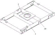
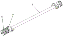
Referring to fig. 1-5, the utility model provides a rotatable automatic sorting gripper device, which comprises a suction disc frame 1, a flange 2 is fixedly arranged at the middle part of the top end of the suction disc frame 1, the flange 2 is fixedly connected with an output shaft of a rotary speed reducer 3, a rotary motor 4 is fixedly arranged on an input shaft of the rotary speed reducer 3, two ends of the suction disc frame 1 are respectively and rotatably connected with a driving shaft 5 and a driven shaft 13, a first belt pulley 6 is fixedly arranged at one end of the driving shaft 5, a second belt pulley 7 is fixedly arranged at two ends of the driving shaft 5, a fixing plate 8 is fixedly arranged at one corner of the top end of the suction disc frame 1, a telescopic speed reducer 9 is fixedly arranged at one side of the fixing plate 8, a telescopic motor 10 is fixedly arranged on the input shaft of the telescopic speed reducer 9, a third belt pulley 11 is fixedly arranged on the output shaft of the telescopic speed reducer 9, the third belt pulley 11 is in transmission connection with the first belt pulley 6 through a first transmission belt 12, the both ends of driven shaft 13 are all fixed and are equipped with fourth belt pulley 14, and two fourth belt pulleys 14 all are connected with two second belt pulley 7 transmissions respectively through second driving belt 15, and the fixed sucking disc subassembly 16 that is equipped with in bottom of sucking disc frame 1 for adsorb the finished product after the laser cutting.
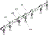
Preferably, the suction cup assembly 16 comprises three cross beam frames 161, wherein the middle cross beam frame 161 is fixedly arranged at the bottom end of the suction cup frame 1, two ends of the left cross beam frame 161 are fixedly connected with the bottoms of the two second transmission belts 15 through mounting plates, two ends of the right cross beam frame 161 are fixedly connected with the tops of the two second transmission belts 15 through mounting plates, a plurality of lifting cylinders 163 are fixedly arranged on one side of each of the three cross beam frames 161 through a connecting plate 162, a suction cup 164 is fixedly arranged on a piston rod of each lifting cylinder 163, and the suction cups 164 are driven to move to adsorb finished products after laser cutting through the extension of the piston rods of the plurality of lifting cylinders 163, so that automatic sorting is performed; the valve island installation frame 17 is fixedly installed on one side of the top end of the suction cup frame 1, and the valve island is conveniently installed through the arranged valve island installation frame 17; mounting seats 18 are fixedly arranged on both sides of the suction cup frame 1 and used for mounting a cross beam frame 161 in the middle; mounting holes are formed in the two ends of the suction disc frame 1 and used for mounting the driving shaft 5 and the driven shaft 13.
When the automatic rotatable sorting gripper device is used, firstly, the transmission shaft of the rotating motor 4 rotates to drive the output shaft of the rotating speed reducer 3 to rotate, so as to drive the whole suction disc frame 1 to rotate, the rotating angle of the suction disc frame is adjusted, then, the positive and negative rotation of the transmission shaft of the telescopic motor 10 drives the positive and negative rotation of the output shaft of the telescopic speed reducer 9, the third belt pulley 11 installed on the output shaft of the telescopic speed reducer 9 is in transmission connection with the first belt pulley 6 installed at one end of the driving shaft 5 through the first transmission belt 12, so as to drive the driving shaft 5 to rotate positively and negatively, the second belt pulleys 7 installed at the two ends of the driving shaft 5 are in transmission connection with the fourth belt pulleys 14 installed at the two ends of the driven shaft 13 through the second transmission belt pulley 15, so as to drive the second transmission belt 15 to rotate positively and negatively, and drive the transverse beam frames 161 at the two sides to open and close, at last, the piston rod extending through the lifting cylinder 163 drives the sucker 164 to adsorb the finished products after laser cutting, so that automatic sorting is performed, the traditional manual sorting is replaced, the labor cost is obviously reduced, and the sorting efficiency is improved.
In the description of the present invention, it should be understood that the indicated orientation or positional relationship is based on the orientation or positional relationship shown in the drawings, and is only for convenience of description and simplification of description, and does not indicate or imply that the indicated device or element must have a particular orientation, be constructed and operated in a particular orientation, and thus should not be construed as limiting the present invention.
In the present invention, unless otherwise explicitly specified or limited, for example, it may be fixedly connected, detachably connected, or integrated; can be mechanically or electrically connected; they may be directly connected or indirectly connected through an intermediate medium, and may be connected through the inside of two elements or in an interaction relationship between two elements, unless otherwise specifically defined, and the specific meaning of the above terms in the present invention will be understood by those skilled in the art according to specific situations.
Although embodiments of the present invention have been shown and described, it will be appreciated by those skilled in the art that changes, modifications, substitutions and alterations can be made in these embodiments without departing from the principles and spirit of the invention, the scope of which is defined in the appended claims and their equivalents.
Claims (5)
1. A rotatable automatic sorting gripper device comprises a gripper frame (1) and is characterized in that a flange plate (2) is fixedly arranged at the middle of the top end of the gripper frame (1), the flange plate (2) is fixedly connected with an output shaft of a rotary speed reducer (3), a rotary motor (4) is fixedly arranged on an input shaft of the rotary speed reducer (3), two ends of the gripper frame (1) are respectively and rotatably connected with a driving shaft (5) and a driven shaft (13), a first belt pulley (6) is fixedly arranged at one end of the driving shaft (5), second belt pulleys (7) are fixedly arranged at two ends of the driving shaft (5), a fixing plate (8) is fixedly arranged at one corner of the top end of the gripper frame (1), a telescopic speed reducer (9) is fixedly arranged at one side of the fixing plate (8), and a telescopic motor (10) is fixedly arranged on the input shaft of the telescopic speed reducer (9), the fixed third belt pulley (11) that is equipped with of output shaft of flexible speed reducer (9), third belt pulley (11) through first driving belt (12) with first belt pulley (6) transmission is connected, the both ends of driven shaft (13) are all fixed and are equipped with fourth belt pulley (14), two fourth belt pulley (14) all through second driving belt (15) respectively with two second belt pulley (7) transmission is connected, the fixed sucking disc subassembly (16) that is equipped with in bottom of sucking disc frame (1).
2. The rotatable automated sorting gripper of claim 1, wherein: sucking disc subassembly (16) include three crossbeam frame (161), wherein lie in the centre crossbeam frame (161) is fixed to be set up the bottom of sucking disc frame (1), wherein lie in the left the both ends of crossbeam frame (161) all pass through mounting panel and two the bottom fixed connection of second drive belt (15), wherein lie in the right side the both ends of crossbeam frame (161) all pass through mounting panel and two the top fixed connection of second drive belt (15), it is three one side of crossbeam frame (161) all has a plurality of lift cylinder (163) through connecting plate (162) fixed mounting, every the piston rod of lift cylinder (163) all fixes and is equipped with sucking disc (164).
3. The rotatable automated sorting gripper of claim 1, wherein: the valve island installation rack is characterized by further comprising a valve island installation rack (17), wherein the valve island installation rack (17) is fixedly installed on one side of the top end of the suction cup rack (1).
4. The rotatable automated sorting gripper of claim 1, wherein: and mounting seats (18) are fixedly arranged on the two sides of the suction disc frame (1).
5. The rotatable automated sorting gripper of claim 1, wherein: mounting holes are formed in the two ends of the suction disc frame (1).
Priority Applications (1)
| Application Number | Priority Date | Filing Date | Title |
|---|---|---|---|
| CN202022453203.XU CN214870633U (en) | 2020-10-29 | 2020-10-29 | Rotatable automatic sorting tongs device |
Applications Claiming Priority (1)
| Application Number | Priority Date | Filing Date | Title |
|---|---|---|---|
| CN202022453203.XU CN214870633U (en) | 2020-10-29 | 2020-10-29 | Rotatable automatic sorting tongs device |
Publications (1)
| Publication Number | Publication Date |
|---|---|
| CN214870633U true CN214870633U (en) | 2021-11-26 |
Family
ID=78885850
Family Applications (1)
| Application Number | Title | Priority Date | Filing Date |
|---|---|---|---|
| CN202022453203.XU Active CN214870633U (en) | 2020-10-29 | 2020-10-29 | Rotatable automatic sorting tongs device |
Country Status (1)
| Country | Link |
|---|---|
| CN (1) | CN214870633U (en) |
-
2020
- 2020-10-29 CN CN202022453203.XU patent/CN214870633U/en active Active
Similar Documents
| Publication | Publication Date | Title |
|---|---|---|
| CN214870633U (en) | Rotatable automatic sorting tongs device | |
| CN209889821U (en) | High-speed rotating lifting adsorption mechanism | |
| CN213380492U (en) | Mechanical arm for milling and grinding | |
| CN114425782A (en) | Rotatable automatic sorting tongs device | |
| CN210281565U (en) | Workpiece conveying mechanism of processing machine | |
| CN208413249U (en) | A kind of robot manipulator structure of numerically-controlled machine tool | |
| CN215147656U (en) | Full-automatic glass edging and drilling assembly line | |
| CN218930995U (en) | Automatic feeding machine | |
| CN214298202U (en) | Mechanical arm and laminating machine composed of same | |
| CN216736471U (en) | Alloy door and window transfer system | |
| CN210763060U (en) | Transverse driving device of transfer machine sucker | |
| CN217372052U (en) | Clamping die for automatic production | |
| CN216173836U (en) | A carousel tool for 3D scribbles limit machine | |
| CN204431039U (en) | Multi-station processing equipment pick and place materials device | |
| CN218464909U (en) | Multipoint positioning reversing grabbing device | |
| CN216426021U (en) | Centering, positioning and reversing mechanism before glass polishing | |
| CN219636365U (en) | Fixed sheet metal part feeding machine | |
| CN220592993U (en) | Tool device for double-glass photovoltaic module | |
| CN215797056U (en) | Curved glass turns over piece equipment | |
| CN218927802U (en) | Manipulator for stamping assembly line | |
| CN216998179U (en) | Double-station glass cutting device | |
| CN217497884U (en) | Sucker assembling and disassembling device | |
| CN216785001U (en) | Material lifting and reversing mechanism | |
| CN218256788U (en) | High-efficient automatic through type laminating machine that cuts | |
| CN215796590U (en) | Transmission roller device |
Legal Events
| Date | Code | Title | Description |
|---|---|---|---|
| GR01 | Patent grant | ||
| GR01 | Patent grant |