CN214753915U - Quick radiating component for new energy automobile battery management - Google Patents
Quick radiating component for new energy automobile battery management Download PDFInfo
- Publication number
- CN214753915U CN214753915U CN202121240417.7U CN202121240417U CN214753915U CN 214753915 U CN214753915 U CN 214753915U CN 202121240417 U CN202121240417 U CN 202121240417U CN 214753915 U CN214753915 U CN 214753915U
- Authority
- CN
- China
- Prior art keywords
- plate
- heat dissipation
- temperature
- new energy
- box
- Prior art date
- Legal status (The legal status is an assumption and is not a legal conclusion. Google has not performed a legal analysis and makes no representation as to the accuracy of the status listed.)
- Expired - Fee Related
Links
Images


Classifications
-
- Y—GENERAL TAGGING OF NEW TECHNOLOGICAL DEVELOPMENTS; GENERAL TAGGING OF CROSS-SECTIONAL TECHNOLOGIES SPANNING OVER SEVERAL SECTIONS OF THE IPC; TECHNICAL SUBJECTS COVERED BY FORMER USPC CROSS-REFERENCE ART COLLECTIONS [XRACs] AND DIGESTS
- Y02—TECHNOLOGIES OR APPLICATIONS FOR MITIGATION OR ADAPTATION AGAINST CLIMATE CHANGE
- Y02E—REDUCTION OF GREENHOUSE GAS [GHG] EMISSIONS, RELATED TO ENERGY GENERATION, TRANSMISSION OR DISTRIBUTION
- Y02E60/00—Enabling technologies; Technologies with a potential or indirect contribution to GHG emissions mitigation
- Y02E60/10—Energy storage using batteries
-
- Y—GENERAL TAGGING OF NEW TECHNOLOGICAL DEVELOPMENTS; GENERAL TAGGING OF CROSS-SECTIONAL TECHNOLOGIES SPANNING OVER SEVERAL SECTIONS OF THE IPC; TECHNICAL SUBJECTS COVERED BY FORMER USPC CROSS-REFERENCE ART COLLECTIONS [XRACs] AND DIGESTS
- Y02—TECHNOLOGIES OR APPLICATIONS FOR MITIGATION OR ADAPTATION AGAINST CLIMATE CHANGE
- Y02T—CLIMATE CHANGE MITIGATION TECHNOLOGIES RELATED TO TRANSPORTATION
- Y02T10/00—Road transport of goods or passengers
- Y02T10/60—Other road transportation technologies with climate change mitigation effect
- Y02T10/70—Energy storage systems for electromobility, e.g. batteries
Abstract
The utility model discloses a quick heat dissipation component for managing new energy automobile batteries, which relates to the technical field of new energy automobiles and comprises a battery installation box and a cooling water tank, wherein the battery installation box comprises a box body, a heat absorption plate is fixedly arranged at the upper end of the inner bottom of the box body in parallel, a bearing pore plate is fixedly arranged above the heat absorption plate, rubber cushions are respectively bonded on the inner walls of the two sides of the box body above the bearing pore plate, a butt joint plate is respectively bonded on the opposite sides of the two rubber cushions, a plurality of temperature equalizing structural plates which are distributed equidistantly are embedded on the surface of the bearing pore plate between the two butt joint plates, and battery panels are respectively arranged between the butt joint plate and the temperature equalizing structural plate and between the temperature equalizing structural plate and the temperature equalizing structural plate, the utility model has the advantages of simple structure, reasonable design, capability of effectively relieving the jolts received by the batteries, and greatly improving the heat dissipation performance by combining water cooling heat dissipation and air cooling heat dissipation, has wide application prospect.
Description
Technical Field
The utility model relates to a new energy automobile technical field, in particular to quick radiator unit is used in new energy automobile battery management.
Background
The new energy automobile adopts unconventional automobile fuel as a power source (or adopts conventional automobile fuel and a novel vehicle-mounted power device), integrates advanced technologies in the aspects of power control and driving of the automobile, and forms an automobile with advanced technical principle, new technology and new structure. The new energy automobile comprises four types of Hybrid Electric Vehicles (HEV), pure electric vehicles (BEV, including solar vehicles), Fuel Cell Electric Vehicles (FCEV), other new energy (such as efficient energy storage devices including super capacitors, flywheels and the like) automobiles and the like, and along with the rapid development of the new energy automobile, the requirements on the performance and the safety of the new energy automobile are higher and higher.
The battery pack of the new energy automobile is used as one of core components of the new energy automobile, the quality of the battery pack directly affects the safety and the service life of the automobile, the temperature of the battery pack and the surrounding environment of the battery pack is changed rapidly due to the fact that the battery pack generates a large amount of heat due to violent chemical reaction in the battery pack in the charging and discharging process, and the service life and the charging and discharging effect of the battery pack are affected even if the temperature is too high, so that the efficient heat dissipation of the battery pack of the new energy automobile is very important; however, when the existing heat dissipation assembly for the new energy automobile battery is used, the internal air circulation performance of the heat dissipation assembly is poor, so that the internal heat of the battery is easily accumulated to cause the damage of the battery, and a shock absorption component for protecting the battery is lacked, so that the battery is easily damaged due to jolt when in use, the use cost is further increased, and unnecessary troubles are caused.
SUMMERY OF THE UTILITY MODEL
The utility model aims to provide a new energy automobile battery management is with quick radiator unit can effectively solve the problem in the background art.
In order to achieve the above purpose, the utility model adopts the following technical scheme:
a quick heat dissipation assembly for managing new energy automobile batteries comprises a battery installation box and a cooling water tank, wherein the battery installation box comprises a box body, the top of the box body is rotatably connected with a box cover through an insertion rod, a lock catch is arranged at the joint of the front of the box cover and the box body, a temperature sensor is installed at the top of the inner side of the box cover, a vent is arranged on the upper end face of the box cover, handles are installed on the outer walls of the two sides of the box body, heat absorption plates are fixedly arranged at the upper end of the bottom of the inner side of the box body in parallel, a bearing pore plate is fixedly arranged above the heat absorption plates, rubber cushions are respectively bonded on the inner walls of the two sides of the box body above the bearing pore plate, abutting plates are respectively bonded on the opposite sides of the two rubber cushions, a plurality of temperature equalizing structural plates which are distributed at equal intervals are embedded on the surface of the bearing pore plate between the two abutting plates, and battery plates are respectively installed between the temperature equalizing structural plates, the water-cooling water tank is characterized in that a controller, a micro circulating water pump and a water storage tank are installed at the bottom of the inner side of the tank body, a liquid inlet pipe is connected to the right side of the water storage tank, an electromagnetic valve is installed on the surface of the liquid inlet pipe, a pipe joint is fixed to the outer side of the tank body, a liquid passing pipe is connected between the cooling water tank and the pipe joint, a liquid throwing port is formed in the top of the cooling water tank, a rotary cover is arranged at the liquid throwing port, a water suction port of the micro circulating water pump is communicated with the bottom of the inner side of the water storage tank, a heat dissipation port is formed in the surface of the left side of the tank body below a heat absorption plate, a heat radiator is installed at one end of the inner side of the tank body of the heat dissipation port, a heat dissipation fan is installed on one side, away from the heat dissipation port, an access plate is installed at the lower end of the front of the tank body, a heat dissipation shutter is installed on the surface of the access plate, and an installation base is connected to the bottom of the outer side of the tank body through a plurality of damping springs, screw holes are formed in two ends of the surface of the mounting base, and fastening bolts are connected to the inner side of the screw holes in a threaded mode.
Preferably, a dustproof filter screen matched with the ventilation opening is installed in the ventilation opening.
Preferably, the heat absorbing plate comprises a rectangular frame, a heat absorbing pipe is fixed on the inner side of the rectangular frame, the heat absorbing pipe is arranged in an S-shaped walking manner, the heat absorbing pipe is of a copper hollow pipe body structure, and a liquid inlet and a liquid outlet are respectively arranged at two ends of the heat absorbing pipe.
Preferably, the outlet port of the miniature circulating water pump is connected with the liquid inlet through a liquid outlet pipe, the liquid outlet is communicated with the inlet port of the radiator, and a liquid return pipe is connected between the outlet port of the radiator and the water storage tank.
Preferably, a liquid level sensor is installed in the water storage tank.
Preferably, the temperature-equalizing structural plate is an integral aluminum alloy vacuum structural body consisting of a heat dissipation plate and a temperature-equalizing plate, the temperature-equalizing plate is provided with two temperature-equalizing plates which are symmetrically arranged and fixed at the front end and the rear end of the upper surface of the heat dissipation plate, T-shaped foam copper is arranged in a hollow part of the temperature-equalizing structural plate, and the temperature-equalizing structural plate is filled with pure water by a vacuum pumping method and sealed by welding.
Preferably, a plurality of suction fans are installed between the bearing orifice plate and the heat absorbing plate, and the suction fans are located below the heat dissipating plate.
Preferably, the inner sides of the plurality of damping springs are all sleeved with damping dampers.
Compared with the prior art, the utility model discloses following beneficial effect has:
1. the utility model can quickly absorb the heat generated in the charging and discharging process of the battery through the arranged heat absorbing plate, and quickly dissipate the absorbed heat out of the box body through the heat dissipating port under the action of the heat radiator and the heat dissipating fan, so as to prevent the discharge efficiency of the battery and the potential safety hazard caused by overhigh temperature in the box body;
2. the utility model discloses a jolt that the battery received can effectively be alleviated to the rubber cushion and the damping spring that set up, prevents that the car from leading to the battery to damage because of vibrations are too big at the in-process of traveling.
Drawings
Fig. 1 is a schematic view of an overall structure of a rapid heat dissipation assembly for managing a new energy vehicle battery of the present invention;
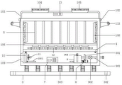
fig. 2 is a front view of the overall appearance structure of the rapid heat dissipation assembly for managing new energy vehicle batteries according to the present invention;
fig. 3 is a top view of the internal structure of the rapid heat dissipation assembly box for managing new energy vehicle batteries according to the present invention;
fig. 4 is a schematic view of the overall structure of the heat absorbing plate of the rapid heat dissipating assembly for managing the new energy vehicle battery of the present invention;
fig. 5 is the utility model relates to a new energy automobile battery management is with inner structure cross-sectional view of quick radiating component samming structural slab.
In the figure: 1. a battery installation box; 101. a box body; 102. a plug rod; 103. a box cover; 104. a vent; 105. a dustproof filter screen; 106. supporting the orifice plate; 107. a rubber cushion; 108. a butt joint plate; 109. a heat dissipation port; 110. locking; 111. an access panel; 112. a heat dissipation louver; 113. a handle; 2. a cooling water tank; 201. a liquid pipe is communicated; 202. a liquid feeding port; 203. a rotating cover; 3. installing a base; 301. a damping spring; 302. a screw hole; 303. damping and damping; 304. fastening a bolt; 4. a heat absorbing plate; 401. a rectangular frame; 402. a heat absorbing tube; 403. a liquid inlet; 404. a liquid outlet; 5. a temperature equalizing structural plate; 501. a heat dissipation plate; 502. a temperature equalizing plate; 503. t-shaped foam copper; 504. pure water; 6. a battery; 7. a controller; 8. a micro circulating water pump; 801. a liquid outlet pipe; 9. a water storage tank; 901. a liquid inlet pipe; 902. an electromagnetic valve; 903. a pipe joint; 904. a liquid level sensor; 10. a heat sink; 1001. a liquid return pipe; 11. a heat dissipation fan; 12. an exhaust fan; 13. a temperature sensor.
Detailed Description
In order to make the technical means, creation features, achievement purposes and functions of the present invention easy to understand, the present invention is further described below with reference to the following embodiments.
As shown in fig. 1-5, a rapid heat dissipation assembly for battery management of a new energy automobile comprises a battery installation box 1 and a cooling water tank 2, wherein the battery installation box 1 comprises a box body 101, the top of the box body 101 is rotatably connected with a box cover 103 through an insertion rod 102, a lock catch 110 is arranged at the joint of the front surface of the box cover 103 and the box body 101, a temperature sensor 13 is installed at the top of the inner side of the box cover 103, a vent 104 is arranged on the upper end surface of the box cover 103, handles 113 are installed on the outer walls of the two sides of the box body 101, a heat absorption plate 4 is fixed at the upper end of the bottom of the inner side of the box body 101 in parallel, a bearing orifice plate 106 is fixed above the heat absorption plate 4, rubber cushions 107 are bonded on the inner walls of the two sides of the box body 101 above the bearing orifice plate 106, abutting plates 108 are bonded on the opposite sides of the two rubber cushions 107, a plurality of temperature equalization structural plates 5 distributed at equal intervals are embedded between the two abutting plates 108 on the surface of the bearing orifice plate 106, the solar panel is arranged between the abutting plate 108 and the temperature-equalizing structural plate 5 and between the temperature-equalizing structural plate 5 and the temperature-equalizing structural plate 5, the controller 7, the micro circulating water pump 8 and the water storage tank 9 are arranged at the bottom of the inner side of the tank body 101, the right side of the water storage tank 9 is connected with a liquid inlet pipe 901, the surface of the liquid inlet pipe 901 is provided with an electromagnetic valve 902, the tail end of the liquid inlet pipe 901 extends to the outer side of the tank body 101 and is fixedly provided with a pipe joint 903, a liquid passing pipe 201 is connected between the cooling water tank 2 and the pipe joint 903, the top of the cooling water tank 2 is provided with a liquid feeding port 202, the liquid feeding port 202 is provided with a rotary cover 203, the water suction port of the micro circulating water pump 8 is communicated with the bottom of the inner side of the water storage tank 9, the heat radiation port 109 is arranged on the surface of the left side of the tank body 101 below the heat absorption plate 4, and the heat radiator 10 is arranged at one end of the inner side of the tank body 101 of the heat radiation port 109, radiator 10 keeps away from one side of thermovent 109 and installs heat dissipation fan 11, maintenance board 111 is installed to the front lower extreme of box 101, maintenance board 111's surface mounting has heat dissipation shutter 112, the outside bottom of box 101 is connected with installation base 3 through a plurality of damping spring 301, screw 302 has been seted up at the surperficial both ends of installation base 3, the inboard threaded connection of screw 302 has fastening bolt 304.
In this embodiment, preferably, the ventilation opening 104 is internally provided with a dustproof filter screen 105 adapted to the ventilation opening, so that dust can be prevented from entering the box 101 to affect air circulation, heat dissipation performance is reduced, and dust is prevented from accumulating on the terminal of the battery 6 to cause safety accidents.
In this embodiment, preferably, the heat absorbing plate 4 includes a rectangular frame 401, a heat absorbing pipe 402 is fixed on an inner side of the rectangular frame 401, the heat absorbing pipe 402 is disposed in an S-shaped moving manner, the heat absorbing pipe 402 is a copper hollow pipe structure, so that a distribution area of the heat absorbing pipe 402 in the case 101 is increased, the heat absorbing pipe 402 can rapidly absorb heat generated in a charging and discharging process of the battery 6, and a liquid inlet 403 and a liquid outlet 404 are respectively disposed at two ends of the heat absorbing pipe 402.
In this embodiment, preferably, the water outlet port of the micro circulating water pump 8 is connected to the liquid inlet 403 through the liquid outlet pipe 801, the liquid outlet 404 is communicated with the water inlet port of the heat sink 10, and the liquid return pipe 1001 is connected between the water outlet port of the heat sink 10 and the water storage tank 9, so as to form a complete water cooling circulating system, and effectively reduce the temperature in the tank 101.
In this embodiment, preferably, a liquid level sensor 904 is installed in the water storage tank 9, and the liquid level sensor can automatically complete the liquid supplementing operation for the water storage tank 9 under the interaction with the controller 7 and the electromagnetic valve 902, so as to prevent the heat dissipation effect of the assembly from being affected by insufficient cooling liquid in the water storage tank 9.
In this embodiment, preferably, the temperature-equalizing structural plate 5 is an integrated aluminum alloy vacuum structural body composed of a heat dissipation plate 501 and a temperature-equalizing plate 502, the temperature-equalizing plate 502 is provided with two temperature-equalizing plates which are symmetrically arranged and fixed at the front end and the rear end of the upper surface of the heat dissipation plate 501, a hollow part of the temperature-equalizing structural plate 5 is provided with T-shaped foam copper 503, the temperature-equalizing structural plate 5 is filled with pure water 504 by a vacuum pumping method and sealed by welding, so that heat accumulated between two adjacent batteries 6 can be quickly absorbed, and safety accidents caused by heat accumulation can be prevented.
In this embodiment, preferably, a plurality of suction fans 12 are installed between the support orifice plate 106 and the heat absorbing plate 4, and the suction fans 12 are located below the heat dissipating plate 501, so that the air circulation inside the case 101 is increased, and the temperature of the heat dissipating plate 501 can be rapidly reduced, thereby achieving the function of rapidly cooling the battery 6 by the temperature equalizing structural plate 5.
In this embodiment, preferably, the inner sides of the plurality of damping springs 301 are all sleeved with damping dampers 303, so as to further enhance the damping effect of the damping springs 301, and make the battery 6 more stable in the driving process of the automobile.
It should be noted that, the utility model relates to a quick heat dissipation assembly for managing new energy automobile battery 6, when in use, sufficient coolant is injected into the cooling water tank 2 through the liquid inlet 202, a part of coolant enters the water storage tank 9 along the liquid through pipe 201 under the action of the controller 7 and the electromagnetic valve 902, the coolant in the water storage tank 9 passes through the heat absorbing plate 4 and the heat radiator 10 in sequence under the action of the micro circulating water pump 8, and then flows back to the water storage tank 9 through the liquid return pipe 1001, so as to realize a complete water cooling circulation system, which can effectively reduce the temperature in the box 101, the heat absorbing pipe 402 fixed on the inner side of the rectangular frame 401 is of a copper hollow pipe structure and is arranged in an S-shaped displacement manner, which can greatly increase the distribution area of the heat absorbing pipe 402 in the box 101, so that the heat absorbing pipe 402 can quickly absorb the heat generated in the charging and discharging process of the battery 6, the heat absorbed by the heat absorbing pipe 402 can be quickly dissipated to the outside the box 101 through the heat radiator 10, the arranged heat radiation fan 11 greatly increases the heat radiation efficiency of the heat radiator 10, when the cooling liquid in the water storage tank 9 is insufficient, the liquid level sensor 904 can send numerical information to the controller 7, the controller 7 sends an instruction to the electromagnetic valve 902, the electromagnetic valve 902 is opened, the cooling liquid automatically flows into the water storage tank 9 from the cooling water tank 2 by a certain amount, the automatic liquid supplementing operation is completed, the intelligent degree is high, the practical effect is good, the temperature equalizing structural plate 5 arranged between two batteries 6 is an integral aluminum alloy vacuum structural body consisting of a heat radiation plate 501 and a temperature equalizing plate 502, the hollow part of the temperature equalizing structural plate 5 is provided with T-shaped foam copper 503, the temperature equalizing structural plate 5 is injected with pure water 504 by a vacuum pumping method and sealed by welding, the heat accumulated between two adjacent batteries 6 can be quickly absorbed, and the temperature equalizing structural plate 5 can keep low temperature by the hot gas on the heat radiation plate 501 of the arranged suction fan 12, the heat on the surface of the battery 6 can be continuously absorbed to form a complete air cooling system, meanwhile, the arranged suction fan 12 can accelerate the circulation of air in the box body 101 and prevent the heat accumulation to cause safety accidents, the ventilation opening 104 is internally provided with the dustproof filter screen 105 matched with the ventilation opening, so that dust can be prevented from entering the box body 101 to influence the circulation of air, the heat dissipation performance is reduced, and meanwhile, the dust is prevented from accumulating on a wiring terminal of the battery 6 to cause safety accidents; jolting that battery 6 received can effectively be alleviated through the rubber cushion 107 and the damping spring 301 that set up, and damping spring 301's inboard all is equipped with damping 303, further strengthens damping spring 301's shock attenuation effect, makes battery 6 can be more steady at the in-process that the car went.
The basic principles and the main features of the invention and the advantages of the invention have been shown and described above. It will be understood by those skilled in the art that the present invention is not limited to the above embodiments, and that the foregoing embodiments and descriptions are provided only to illustrate the principles of the present invention without departing from the spirit and scope of the present invention. The scope of the invention is defined by the appended claims and equivalents thereof.
Claims (8)
1. The utility model provides a new energy automobile battery management is with quick radiator unit, includes battery install bin (1) and cooling water tank (2), its characterized in that: battery install bin (1) includes box (101), the top of box (101) is rotated through bayonet pole (102) and is connected with case lid (103), the front of case lid (103) disposes hasp (110) with the junction of box (101), temperature sensor (13) are installed at the inboard top of case lid (103), the up end of case lid (103) is equipped with vent (104), handle (113) are all installed to the both sides outer wall of box (101), the inboard bottom upper end of box (101) is fixed with parallel placement absorber plate (4), the top of absorber plate (4) is fixed with bearing orifice plate (106), the top of bearing orifice plate (106) all bonds in the both sides inner wall of box (101) and has rubber cushion (107), two relative one side of rubber cushion (107) all bonds and has butt joint board (108), two between butt joint board (108) in the surface of bearing orifice plate (106) inlay and be equipped with a plurality of equidistance distribution all The temperature-equalizing structure comprises a temperature-equalizing structure plate (5), cell plates (6) are respectively arranged between the abutting plate (108) and the temperature-equalizing structure plate (5) and between the temperature-equalizing structure plate (5) and the temperature-equalizing structure plate (5), a controller (7), a micro circulating water pump (8) and a water storage tank (9) are arranged at the bottom of the inner side of the tank body (101), a liquid inlet pipe (901) is connected to the right side of the water storage tank (9), an electromagnetic valve (902) is arranged on the surface of the liquid inlet pipe (901), the tail end of the liquid inlet pipe (901) extends to the outer side of the tank body (101) and is fixedly provided with a pipe joint (903), a liquid communicating pipe (201) is connected between the cooling water tank (2) and the pipe joint (903), a liquid feeding port (202) is arranged at the top of the cooling water tank (2), a rotary cover (203) is arranged at the liquid feeding port (202), and a water suction port of the micro circulating water pump (8) is communicated with the bottom of the inner side of the water storage tank (9), the utility model discloses a heat sink, including box (101), radiator (109), maintenance board (111), heat sink (10) are installed to the inboard one end of box (101) in radiator (109), radiator (10) are kept away from one side of radiator (109) and are installed heat dissipation fan (11), maintenance board (111) are installed to the front lower extreme of box (101), the surface mounting of maintenance board (111) has heat dissipation shutter (112), the outside bottom of box (101) is connected with installation base (3) through a plurality of damping spring (301), screw (302) have been seted up at the surperficial both ends of installation base (3), the inboard threaded connection of screw (302) has fastening bolt (304).
2. The quick heat dissipation assembly for battery management of the new energy automobile according to claim 1, characterized in that: and a dustproof filter screen (105) matched with the ventilation opening (104) is arranged in the ventilation opening.
3. The quick heat dissipation assembly for battery management of the new energy automobile according to claim 1, characterized in that: the heat absorption plate (4) comprises a rectangular frame (401), a heat absorption pipe (402) is fixed on the inner side of the rectangular frame (401), the heat absorption pipe (402) is arranged in an S-shaped moving mode, the heat absorption pipe (402) is of a copper hollow pipe body structure, and a liquid inlet (403) and a liquid outlet (404) are respectively formed in two ends of the heat absorption pipe (402).
4. The quick heat dissipation assembly for battery management of the new energy automobile according to claim 3, wherein: the outlet port of the miniature circulating water pump (8) is connected with the liquid inlet (403) through the liquid outlet pipe (801), the liquid outlet (404) is communicated with the inlet port of the radiator (10), and a liquid return pipe (1001) is connected between the outlet port of the radiator (10) and the water storage tank (9).
5. The quick heat dissipation assembly for battery management of the new energy automobile according to claim 1, characterized in that: and a liquid level sensor (904) is arranged in the water storage tank (9).
6. The quick heat dissipation assembly for battery management of the new energy automobile according to claim 1, characterized in that: the temperature-equalizing structure plate (5) is an integral aluminum alloy vacuum structure body consisting of a heat dissipation plate (501) and a temperature-equalizing plate (502), the temperature-equalizing plate (502) is provided with two temperature-equalizing plates and symmetrically arranged at the front end and the rear end of the upper surface of the heat dissipation plate (501), T-shaped foam copper (503) is arranged in the hollow part of the temperature-equalizing structure plate (5), and pure water (504) is injected into the temperature-equalizing structure plate (5) through a vacuum pumping method and is sealed through welding.
7. The quick heat dissipation assembly for battery management of the new energy automobile according to claim 6, wherein: a plurality of suction fans (12) are arranged between the bearing orifice plate (106) and the heat absorbing plate (4), and the suction fans (12) are positioned below the heat radiating plate (501).
8. The quick heat dissipation assembly for battery management of the new energy automobile according to claim 1, characterized in that: the inner sides of the shock absorption springs (301) are all sleeved with shock absorption dampers (303).
Priority Applications (1)
| Application Number | Priority Date | Filing Date | Title |
|---|---|---|---|
| CN202121240417.7U CN214753915U (en) | 2021-06-04 | 2021-06-04 | Quick radiating component for new energy automobile battery management |
Applications Claiming Priority (1)
| Application Number | Priority Date | Filing Date | Title |
|---|---|---|---|
| CN202121240417.7U CN214753915U (en) | 2021-06-04 | 2021-06-04 | Quick radiating component for new energy automobile battery management |
Publications (1)
| Publication Number | Publication Date |
|---|---|
| CN214753915U true CN214753915U (en) | 2021-11-16 |
Family
ID=78627917
Family Applications (1)
| Application Number | Title | Priority Date | Filing Date |
|---|---|---|---|
| CN202121240417.7U Expired - Fee Related CN214753915U (en) | 2021-06-04 | 2021-06-04 | Quick radiating component for new energy automobile battery management |
Country Status (1)
| Country | Link |
|---|---|
| CN (1) | CN214753915U (en) |
Cited By (2)
| Publication number | Priority date | Publication date | Assignee | Title |
|---|---|---|---|---|
| CN114245673A (en) * | 2021-12-17 | 2022-03-25 | 贵州电网有限责任公司 | Movable heat dissipation and energy storage box |
| CN115579553A (en) * | 2022-11-21 | 2023-01-06 | 安徽元横能源科技有限公司 | Electric energy conversion system of intelligent light storage micro-grid system |
-
2021
- 2021-06-04 CN CN202121240417.7U patent/CN214753915U/en not_active Expired - Fee Related
Cited By (2)
| Publication number | Priority date | Publication date | Assignee | Title |
|---|---|---|---|---|
| CN114245673A (en) * | 2021-12-17 | 2022-03-25 | 贵州电网有限责任公司 | Movable heat dissipation and energy storage box |
| CN115579553A (en) * | 2022-11-21 | 2023-01-06 | 安徽元横能源科技有限公司 | Electric energy conversion system of intelligent light storage micro-grid system |
Similar Documents
| Publication | Publication Date | Title |
|---|---|---|
| CN214753915U (en) | Quick radiating component for new energy automobile battery management | |
| CN111129655A (en) | Self-discharge less and cycle number more integrated new energy automobile battery | |
| CN110379964A (en) | A kind of new energy electric motor vehicle battery heat radiation protection device | |
| CN210224225U (en) | New forms of energy electric motor car battery heat dissipation protection device | |
| CN211320158U (en) | Heat dissipation auxiliary assembly for new energy automobile | |
| CN212164061U (en) | Dustproof install bin is prevented in heat dissipation of 5G communication equipment | |
| CN210502356U (en) | A samming structure for new energy automobile chassis | |
| CN212277300U (en) | Self-discharge less and cycle number more integrated new energy automobile battery | |
| CN207305242U (en) | A kind of charging pile radiator | |
| CN214477648U (en) | Promote heat abstractor of electric automobile battery | |
| CN211376773U (en) | Supporting and heat radiating device for vehicle power device | |
| CN216389519U (en) | Power battery heat radiation structure of dump truck in electric yard | |
| CN213718537U (en) | Heat dissipation mechanism for new energy automobile battery management | |
| CN112768801A (en) | Battery charging heat radiation structure of new energy automobile | |
| CN211208627U (en) | Battery box heat radiation structure of new energy automobile | |
| CN216120473U (en) | New energy automobile battery cooling structure | |
| CN215705750U (en) | Put a formula electric automobile intelligent charging stake suitable for parking area | |
| CN215911518U (en) | Circulation cooling structure of new energy automobile power battery group | |
| CN219371123U (en) | Battery pack radiator | |
| CN113078402B (en) | New energy automobile is with radiating battery box of being convenient for | |
| CN213692238U (en) | Battery for new energy automobile convenient to installation | |
| CN213693447U (en) | High-efficient radiating anticollision type converter | |
| CN218975568U (en) | Battery compartment with good heat dissipation effect | |
| CN212848577U (en) | A battery package structure for new energy automobile | |
| CN216216235U (en) | New energy automobile motor |
Legal Events
| Date | Code | Title | Description |
|---|---|---|---|
| GR01 | Patent grant | ||
| GR01 | Patent grant | ||
| CF01 | Termination of patent right due to non-payment of annual fee |
Granted publication date: 20211116 |
|
| CF01 | Termination of patent right due to non-payment of annual fee |