CN210224225U - New forms of energy electric motor car battery heat dissipation protection device - Google Patents
New forms of energy electric motor car battery heat dissipation protection device Download PDFInfo
- Publication number
- CN210224225U CN210224225U CN201920958895.8U CN201920958895U CN210224225U CN 210224225 U CN210224225 U CN 210224225U CN 201920958895 U CN201920958895 U CN 201920958895U CN 210224225 U CN210224225 U CN 210224225U
- Authority
- CN
- China
- Prior art keywords
- fixed
- heat dissipation
- heat
- protection device
- storage battery
- Prior art date
- Legal status (The legal status is an assumption and is not a legal conclusion. Google has not performed a legal analysis and makes no representation as to the accuracy of the status listed.)
- Expired - Fee Related
Links
Images


Classifications
-
- Y—GENERAL TAGGING OF NEW TECHNOLOGICAL DEVELOPMENTS; GENERAL TAGGING OF CROSS-SECTIONAL TECHNOLOGIES SPANNING OVER SEVERAL SECTIONS OF THE IPC; TECHNICAL SUBJECTS COVERED BY FORMER USPC CROSS-REFERENCE ART COLLECTIONS [XRACs] AND DIGESTS
- Y02—TECHNOLOGIES OR APPLICATIONS FOR MITIGATION OR ADAPTATION AGAINST CLIMATE CHANGE
- Y02E—REDUCTION OF GREENHOUSE GAS [GHG] EMISSIONS, RELATED TO ENERGY GENERATION, TRANSMISSION OR DISTRIBUTION
- Y02E60/00—Enabling technologies; Technologies with a potential or indirect contribution to GHG emissions mitigation
- Y02E60/10—Energy storage using batteries
Abstract
The utility model discloses a new forms of energy electric motor car battery heat dissipation protection device, the on-line screen storage device comprises a base, the top of base is fixed with the fixed plate, the square hole has been seted up at the middle part of fixed plate, install first radiator fan in the square hole, it is protruding evenly to be fixed with a plurality of block form on the arc shock attenuation board, the bottom both sides of mounting panel all are fixed with the recess of a plurality of and cubic protruding adaptation, fixed mounting has battery body on the mounting panel, battery body's both sides are hugged closely there is the heat conduction casing, one side central authorities that battery body was kept away from to the heat conduction casing are fixed with the heat conduction pole, the upper and lower both ends symmetry of heat conduction casing articulates there is the head rod, all be fixed with vertical baffle around the base, spout and slider. The utility model discloses a set up a plurality of heat radiation structure and shock-absorbing structure and protect the battery, guarantee the normal work of battery, can prolong its life.
Description
Technical Field
The utility model relates to a new energy automobile accessory technical field specifically is a new energy electric motor car battery heat dissipation protection device.
Background
The new energy automobile adopts unconventional automobile fuel as a power source (or adopts conventional automobile fuel and a novel vehicle-mounted power device), integrates advanced technologies in the aspects of power control and driving of the automobile, forms an automobile with advanced technical principle, new technology and new structure, and comprises a pure electric automobile, an extended range electric automobile, a hybrid electric automobile, a fuel cell electric automobile, a hydrogen engine automobile, other new energy automobiles and the like. At present, in China, new energy automobiles mainly refer to pure electric automobiles, extended range electric automobiles, plug-in hybrid electric automobiles and fuel cell electric automobiles, conventional hybrid electric automobiles are divided into energy-saving automobiles, and from the development of new energy automobiles all over the world, power supplies of the new energy automobiles mainly comprise lithium ion batteries, nickel-hydrogen batteries, fuel cells, lead-acid batteries and super capacitors, wherein the super capacitors are mostly in the form of auxiliary power sources, the main reason is that the battery technologies are not completely mature or have obvious defects, compared with the conventional automobiles, the new energy automobiles have a great difference in cost, power and mileage, and the new energy automobiles are also important reasons for restricting the development of the new energy automobiles.
Energy storage of new energy vehicles (oil-electricity hybrid vehicles and pure electric vehicles) requires high-performance storage batteries, and in the use process, the temperature inside the storage batteries is increased to exceed the normal use temperature of the storage batteries due to charging and discharging of large current, and even the batteries are broken, leaked, ignited and exploded, so that the reliability and safety of the batteries are affected. Therefore, in a battery management system of a new energy automobile, a fan and a ventilation system are often provided for dissipating heat of a battery.
The existing new energy automobile storage battery is used as a core component of an automobile, and often, because the existing protection devices of the storage batteries have more defects in the use process, especially the damage degree of the storage batteries in the collision process has a great influence on the safety of the whole automobile, on one hand, the existing protection devices of the storage batteries have insufficient protection level on the storage batteries and have no anti-collision measures, so the charging devices can be seriously damaged; the storage battery can flow out flammable liquid after collision, and because no fireproof measures are adopted, the storage battery is easy to catch fire and explode to cause danger.
SUMMERY OF THE UTILITY MODEL
The to-be-solved technical problem of the utility model is to overcome current defect, provide a new forms of energy electric motor car battery heat dissipation protection device, can effectively solve the problem in the background art.
In order to achieve the above object, the utility model provides a following technical scheme: a new energy electric vehicle storage battery heat dissipation protection device comprises a base, wherein a fixed plate is fixed at the top of the base, a square hole is formed in the middle of the fixed plate, a first heat dissipation fan is installed in the square hole, arc-shaped damping plates are fixed on the front side and the rear side of the fixed plate respectively, a plurality of block-shaped bulges are uniformly fixed on the arc-shaped damping plates, a mounting plate is installed at the top of each arc-shaped damping plate in a matched manner, a plurality of grooves matched with the block-shaped bulges are fixed on both sides of the bottom of the mounting plate, a storage battery body is fixedly installed on the mounting plate, heat conduction shells are tightly attached to both sides of the storage battery body, a second heat dissipation fan is arranged in each heat conduction shell, a heat conduction rod is fixed in the center of one side, away from the storage battery body, of each heat, the end part of the first connecting rod is fixed with a sliding block, the periphery of the base is fixed with a vertical baffle, the upper end and the lower end of the inner wall of one side of the vertical baffle are respectively provided with a sliding groove, the sliding grooves are matched with the sliding block, the middle part of the vertical baffle is provided with a round hole, a metal net is arranged in the round hole, the middle part of the metal net is provided with a fixed sleeve in a penetrating way, the heat conducting rod penetrates through the fixed sleeve and extends to the outer side of the vertical baffle to be connected with a heat dissipation assembly, compression springs are sleeved on the two sides of the fixed sleeve on the heat conducting rod, the top part of the vertical baffle is hinged with an cover plate, the bottom part of the cover plate is fixedly provided with a top plate, the bottom end of the top plate is provided with a plurality of parallel sliding rails, the top, the middle parts of the two second connecting rods are provided with buffer springs, the top parts of the second connecting rods are provided with idler wheels, and the idler wheels are movably arranged on the sliding rails.
As an optimized technical scheme of the utility model, the base four corners is equipped with a plurality of fixed orificess.
As an optimal technical scheme of the utility model, battery body below and two leave the heat dissipation cavity between the arc shock attenuation board.
As a preferred technical scheme of the utility model, radiator unit includes the heating panel, the inside of heating panel is hollow structure, the heating panel is kept away from a plurality of align to grid's louvre is seted up to one side of vertical baffle, the upper and lower both ends of heating panel all are equipped with a plurality of radiating fin.
As the utility model discloses an optimal technical scheme, the top of apron is equipped with the cold wind case, the top of cold wind case is equipped with the air-cooler, the bottom UNICOM of cold wind case has the ventilation pipe, the lower extreme of ventilation pipe runs through in proper order apron and roof extend to battery body's top, be equipped with the dust filter screen in the cold wind case.
As an optimal technical scheme of the utility model, arc shock attenuation board symmetry is located first radiator fan's both sides.
As an optimized technical scheme of the utility model, first radiator fan with second radiator fan is the four-bladed fan.
As an optimized technical solution of the present invention, the block-shaped protrusion is equal to the number of the grooves.
Compared with the prior art, the beneficial effects of the utility model are that:
1. the utility model discloses a set up base, fixed plate, arc shock attenuation board and mounting panel, can carry out fixed mounting to the battery on the horizontal plane, cubic arch and recess cooperation can prevent to go about the car and rock and lead to the battery body to shift.
2. The utility model discloses a set up first radiator fan and second radiator fan, can realize the flow to battery body surface air, take away the hot-air around the battery body, be convenient for quick, direct heat dissipation.
3. The utility model discloses a set up heat conduction casing, heat conduction pole and radiator unit, be convenient for transmit the too high heat conduction casing of heat that produces the battery body surface to the heat conduction pole, transmit to radiator unit by the heat conduction pole again on, transmit heat to the outside by radiator unit at last.
4. The utility model discloses a set up buffer spring, fixed cover, head rod, damping spring, rubber buffer block, second connecting rod and gyro wheel, the vibrations of being convenient for producing at the in-process of traveling are protected battery body, guarantee battery body's safety.
5. The utility model discloses a set up cold-blast box, air-cooler, ventilation pipe and dust filter screen, be convenient for in time change the gas of device inside with outside cold air and filter the dust and guarantee the clean of inside gas.
Drawings
Fig. 1 is a schematic front structural view of the present invention;
fig. 2 is a schematic side view of the present invention;
fig. 3 is a top view of the fixing plate of the present invention;
fig. 4 is a bottom view of the top plate of the present invention;
fig. 5 is a schematic structural view of the heat dissipation assembly of the present invention.
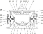
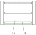
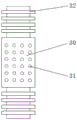
In the figure: 1. a base; 2. a fixing plate; 3. a square hole; 4. a first heat dissipation fan; 5. an arc-shaped damping plate; 6. a block-shaped bulge; 7. mounting a plate; 8. a groove; 9. a battery body; 10. a thermally conductive housing; 11. a second heat dissipation fan; 12. a heat conducting rod; 13. a first connecting rod; 14. a slider; 15. a vertical baffle; 16. a chute; 17. a circular hole; 18. a metal mesh; 19. fixing a sleeve; 20. a heat dissipating component; 21. a compression spring; 22. a cover plate; 23. a top plate; 24. a slide rail; 25. a buffer rubber block; 26. a second connecting rod; 27. a buffer spring; 28. a roller; 29. a heat dissipation cavity; 30. a heat dissipation plate; 31. heat dissipation holes; 32. a heat dissipating fin; 33. a cold air box; 34. an air cooler; 35. a vent pipe; 36. a dust filter screen.
Detailed Description
The technical solutions in the embodiments of the present invention will be described clearly and completely with reference to the accompanying drawings in the embodiments of the present invention, and it is obvious that the described embodiments are only some embodiments of the present invention, not all embodiments. Based on the embodiments in the present invention, all other embodiments obtained by a person skilled in the art without creative work belong to the protection scope of the present invention.
Referring to fig. 1-5, the present invention provides a technical solution: a new energy electric vehicle storage battery heat dissipation protection device comprises a base 1, wherein a fixed plate 2 is fixed at the top of the base 1, a square hole 3 is formed in the middle of the fixed plate 2, a first heat dissipation fan 4 is installed in the square hole 3, arc-shaped shock absorption plates 5 are fixed on the front side and the rear side of the fixed plate 2 respectively, a plurality of block-shaped bulges 6 are uniformly fixed on the arc-shaped shock absorption plates 5, a mounting plate 7 is installed at the top of the arc-shaped shock absorption plates 5 in a matching manner, a plurality of grooves 8 matched with the block-shaped bulges 6 are fixed on the two sides of the bottom of the mounting plate 7 respectively, a storage battery body 9 is fixedly installed on the mounting plate 7, heat conduction shells 10 are tightly attached to the two sides of the storage battery body 9, a second heat dissipation fan 11 is arranged inside the heat conduction shells 10, and a heat conduction rod 12 is fixed, the upper end and the lower end of the heat conducting shell 10 are symmetrically hinged with first connecting rods 13, the end of each first connecting rod 13 is fixed with a slider 14, vertical baffles 15 are fixed around the base 1, the upper end and the lower end of the inner wall of one side of each vertical baffle 15 are respectively provided with a sliding chute 16, each sliding chute 16 is matched with the corresponding slider 14, the middle of each vertical baffle 15 is provided with a round hole 17, a metal mesh 18 is arranged in each round hole 17, the middle of each metal mesh 18 is provided with a fixing sleeve 19 in a penetrating manner, each heat conducting rod 12 penetrates through the fixing sleeve 19 and extends to the outer side of the corresponding vertical baffle 15 to be connected with a heat radiating assembly 20, compression springs 21 are respectively sleeved on the two sides of each fixing sleeve 19 on each heat conducting rod 12, the top of each vertical baffle 15 is hinged with an cover plate 22, the bottom of each cover plate 22 is fixedly provided with, the top of battery body 9 is equipped with a plurality of cushion rubber blocks 25, the top both ends of cushion rubber block 25 articulate respectively has two second connecting rods 26, two the middle part of second connecting rod 26 is equipped with buffer spring 27, gyro wheel 28 is installed at the top of second connecting rod 26, gyro wheel 28 movable mounting in on the slide rail 24.
A plurality of fixing holes are formed in four corners of the base 1, a heat dissipation cavity 29 is reserved between the lower portion of the storage battery body 9 and the two arc-shaped damping plates 5, the heat dissipation assembly 20 comprises a heat dissipation plate 30, the heat dissipation plate 30 is of a hollow structure, a plurality of heat dissipation holes 31 which are uniformly arranged are formed in one side, away from the vertical baffle 15, of the heat dissipation plate 30, a plurality of heat dissipation fins 32 are arranged at the upper end and the lower end of the heat dissipation plate 30, a cold air box 33 is arranged at the top of the cover plate 22, an air cooler 34 is arranged at the top of the cold air box 33, a ventilation pipe 35 is communicated with the bottom of the cold air box 33, the lower end of the ventilation pipe 35 sequentially penetrates through the cover plate 22 and the top plate 23 and extends to the upper portion of the storage battery body 9, a dust filter screen 36 is arranged in the cold, the first heat dissipation fan 4 and the second heat dissipation fan 11 are both four-blade fans, and the number of the block-shaped protrusions 6 is equal to that of the grooves 8.
The utility model discloses a theory of operation and use flow: when in use, the storage battery body 9 can be fixed and fixed on a horizontal plane for 9 displacement by arranging the base 1, the fixed plate 2, the arc-shaped damping plate 5 and the mounting plate 7; the first cooling fan 4 and the second cooling fan 11 are arranged, so that air on the surface of the storage battery body 9 can flow, a hole is reserved between the arc-shaped damping plates 5 and the fixing plate 2, and a cooling cavity 29 is reserved between the lower part of the storage battery body 9 and the two arc-shaped damping plates 5, so that hot air around the storage battery body 9 can be taken away conveniently, and quick and direct cooling is facilitated; through the arrangement of the heat conduction shell 10, the heat conduction rod 12 and the heat dissipation assembly 20, heat generated on the surface of the storage battery body 9 is conveniently transferred to the heat conduction rod 12 through the heat conduction shell 10, then transferred to the heat dissipation assembly 20 through the heat conduction rod 12, and finally transferred to the outside through the heat dissipation assembly 20, and the heat dissipation assembly 20 dissipates heat through the hollow heat dissipation plate 30, the plurality of heat dissipation holes 31 and the plurality of heat dissipation fins 32; by arranging the compression spring 21, the fixed sleeve 19, the first connecting rod 13, the buffer spring 27, the rubber buffer block 25, the second connecting rod 26 and the roller 28, the storage battery body 9 is protected by the vibration generated in the driving process, and the safety of the storage battery body 9 is ensured; through setting up cold-blast box 33, air-cooler 34, ventilation pipe 35 and dust filter screen 36, be convenient for in time change the gas of device inside with outside cold air and filter and fall the dust and guarantee the clean of inside gas, the utility model discloses a set up a plurality of heat radiation structure and shock-absorbing structure and protect the battery, guarantee the normal work of battery, can prolong its life.
Although embodiments of the present invention have been shown and described, it will be appreciated by those skilled in the art that changes, modifications, substitutions and alterations can be made in these embodiments without departing from the principles and spirit of the invention, the scope of which is defined in the appended claims and their equivalents.
Claims (6)
1. The utility model provides a new forms of energy electric motor car battery heat dissipation protection device, includes base (1), its characterized in that: the heat-conducting type solar battery is characterized in that a fixing plate (2) is fixed at the top of the base (1), a square hole (3) is formed in the middle of the fixing plate (2), a first heat-radiating fan (4) is installed in the square hole (3), arc-shaped damping plates (5) are fixed on the front side and the rear side of the fixing plate (2), a plurality of block-shaped bulges (6) are uniformly fixed on the arc-shaped damping plates (5), a mounting plate (7) is installed at the top of the arc-shaped damping plates (5) in a matched mode, a plurality of grooves (8) matched with the block-shaped bulges (6) are fixed on the two sides of the bottom of the mounting plate (7), a battery body (9) is fixedly installed on the mounting plate (7), a heat-conducting shell (10) is tightly attached to the two sides of the battery body (9), a second heat-radiating fan (11) is arranged in the heat-conducting shell (10), and a heat-conducting rod, the upper end and the lower end of the heat conduction shell (10) are symmetrically hinged with first connecting rods (13), the end part of each first connecting rod (13) is fixed with a sliding block (14), vertical baffles (15) are fixed on the periphery of the base (1), the upper end and the lower end of the inner wall of one side of each vertical baffle (15) are respectively provided with a sliding groove (16), each sliding groove (16) is matched with the corresponding sliding block (14), the middle part of each vertical baffle (15) is provided with a round hole (17), a metal mesh (18) is arranged in each round hole (17), the middle part of each metal mesh (18) is provided with a fixing sleeve (19) in a penetrating manner, each heat conduction rod (12) penetrates through the fixing sleeve (19) and extends to the outer side of the corresponding vertical baffle (15) and is connected with a heat dissipation assembly (20), the two sides of each fixing sleeve (19) on each heat conduction rod (12) are respectively provided with a compression spring, a top plate (23) is fixedly mounted at the bottom of the cover plate (22), a plurality of parallel sliding rails (24) are arranged at the bottom end of the top plate (23), a plurality of buffer rubber blocks (25) are arranged at the top of the storage battery body (9), two second connecting rods (26) are respectively hinged to two ends of the top of each buffer rubber block (25), a buffer spring (27) is arranged in the middle of each second connecting rod (26), a roller (28) is mounted at the top of each second connecting rod (26), and the roller (28) is movably mounted on the corresponding sliding rail (24); a plurality of fixing holes are formed in four corners of the base (1); and a heat dissipation cavity (29) is reserved between the lower part of the storage battery body (9) and the two arc-shaped damping plates (5).
2. The new energy electric vehicle storage battery heat dissipation protection device of claim 1, characterized in that: radiating component (20) includes heating panel (30), the inside of heating panel (30) is hollow structure, heating panel (30) are kept away from a plurality of align to grid's louvre (31) is seted up to one side of vertical baffle (15), the upper and lower both ends of heating panel (30) all are equipped with a plurality of radiating fin (32).
3. The new energy electric vehicle storage battery heat dissipation protection device of claim 1, characterized in that: the top of apron (22) is equipped with cold wind box (33), the top of cold wind box (33) is equipped with air-cooler (34), the bottom UNICOM of cold wind box (33) has ventilation pipe (35), the lower extreme of ventilation pipe (35) runs through in proper order apron (22) and roof (23) extend to the top of battery body (9), be equipped with dust filter screen (36) in cold wind box (33).
4. The new energy electric vehicle storage battery heat dissipation protection device of claim 1, characterized in that: the arc-shaped damping plates (5) are symmetrically arranged on two sides of the first radiating fan (4).
5. The new energy electric vehicle storage battery heat dissipation protection device of claim 1, characterized in that: the first heat radiation fan (4) and the second heat radiation fan (11) are both four-blade fans.
6. The new energy electric vehicle storage battery heat dissipation protection device of claim 1, characterized in that: the number of the block-shaped bulges (6) is equal to that of the grooves (8).
Priority Applications (1)
| Application Number | Priority Date | Filing Date | Title |
|---|---|---|---|
| CN201920958895.8U CN210224225U (en) | 2019-06-25 | 2019-06-25 | New forms of energy electric motor car battery heat dissipation protection device |
Applications Claiming Priority (1)
| Application Number | Priority Date | Filing Date | Title |
|---|---|---|---|
| CN201920958895.8U CN210224225U (en) | 2019-06-25 | 2019-06-25 | New forms of energy electric motor car battery heat dissipation protection device |
Publications (1)
| Publication Number | Publication Date |
|---|---|
| CN210224225U true CN210224225U (en) | 2020-03-31 |
Family
ID=69933827
Family Applications (1)
| Application Number | Title | Priority Date | Filing Date |
|---|---|---|---|
| CN201920958895.8U Expired - Fee Related CN210224225U (en) | 2019-06-25 | 2019-06-25 | New forms of energy electric motor car battery heat dissipation protection device |
Country Status (1)
| Country | Link |
|---|---|
| CN (1) | CN210224225U (en) |
Cited By (4)
| Publication number | Priority date | Publication date | Assignee | Title |
|---|---|---|---|---|
| CN111313125A (en) * | 2020-04-13 | 2020-06-19 | 合肥森印科技有限公司 | Battery placing box assembly for new energy automobile |
| CN112428810A (en) * | 2020-12-09 | 2021-03-02 | 福建中维动力科技股份有限公司 | Vehicle body supporting structure of hybrid vehicle |
| CN113054221A (en) * | 2021-03-19 | 2021-06-29 | 宁波瑞东技术转移有限公司 | Novel cooling system of hydrogen energy automobile fuel cell stack |
| CN113555212A (en) * | 2021-07-19 | 2021-10-26 | 杭州南威电力有限公司 | Waterproof antidetonation type intelligent capacitor |
-
2019
- 2019-06-25 CN CN201920958895.8U patent/CN210224225U/en not_active Expired - Fee Related
Cited By (4)
| Publication number | Priority date | Publication date | Assignee | Title |
|---|---|---|---|---|
| CN111313125A (en) * | 2020-04-13 | 2020-06-19 | 合肥森印科技有限公司 | Battery placing box assembly for new energy automobile |
| CN112428810A (en) * | 2020-12-09 | 2021-03-02 | 福建中维动力科技股份有限公司 | Vehicle body supporting structure of hybrid vehicle |
| CN113054221A (en) * | 2021-03-19 | 2021-06-29 | 宁波瑞东技术转移有限公司 | Novel cooling system of hydrogen energy automobile fuel cell stack |
| CN113555212A (en) * | 2021-07-19 | 2021-10-26 | 杭州南威电力有限公司 | Waterproof antidetonation type intelligent capacitor |
Similar Documents
| Publication | Publication Date | Title |
|---|---|---|
| CN210224225U (en) | New forms of energy electric motor car battery heat dissipation protection device | |
| CN110379964A (en) | A kind of new energy electric motor vehicle battery heat radiation protection device | |
| CN109065797A (en) | A kind of protective cover for new energy car battery | |
| CN108520990B (en) | Electric automobile battery box and heat dissipation and heating system and method thereof | |
| CN108649297B (en) | Cooling system for new energy automobile | |
| CN110137621B (en) | Battery heat radiating device for new energy automobile | |
| CN206059459U (en) | A kind of temperature control battery bag | |
| CN210640342U (en) | Battery package thermal management device that heat dispersion is good | |
| CN210379339U (en) | Battery package thermal management system that forced air cooling water-cooling combined together | |
| CN214753915U (en) | Quick radiating component for new energy automobile battery management | |
| CN210628450U (en) | Cooling device for new energy automobile battery | |
| CN112259828B (en) | New energy automobile battery package heat abstractor | |
| CN210092164U (en) | Lithium battery pack for automobile | |
| CN215869552U (en) | Power battery heat management module structure adaptive to multifunctional foam sealing gasket | |
| CN211809008U (en) | New energy automobile energy storage system | |
| CN218336889U (en) | Ready-package on-vehicle positioner that navigation engineering used | |
| CN220873742U (en) | Dust protection assembly for hybrid powertrain system | |
| CN214099764U (en) | High-rate lithium titanate fast-charging power battery aluminum shell with high overcurrent performance | |
| CN220627914U (en) | Shock-absorbing heat-insulating protection device for lithium battery | |
| CN219499004U (en) | Mobile power supply charging device | |
| CN218241959U (en) | Portable lithium ion battery of electric vehicle | |
| CN219017707U (en) | Hydrogen fuel cell with improved structure | |
| CN218586218U (en) | On-vehicle power lithium cell package with anticollision structure | |
| CN220042000U (en) | Anti-collision battery thermal management device | |
| CN219553767U (en) | Lithium battery energy storage device |
Legal Events
| Date | Code | Title | Description |
|---|---|---|---|
| GR01 | Patent grant | ||
| GR01 | Patent grant | ||
| CF01 | Termination of patent right due to non-payment of annual fee | ||
| CF01 | Termination of patent right due to non-payment of annual fee |
Granted publication date: 20200331 Termination date: 20210625 |