CN211376773U - Supporting and heat radiating device for vehicle power device - Google Patents
Supporting and heat radiating device for vehicle power device Download PDFInfo
- Publication number
- CN211376773U CN211376773U CN202021231275.3U CN202021231275U CN211376773U CN 211376773 U CN211376773 U CN 211376773U CN 202021231275 U CN202021231275 U CN 202021231275U CN 211376773 U CN211376773 U CN 211376773U
- Authority
- CN
- China
- Prior art keywords
- shell
- fixedly connected
- vehicle power
- mounting plate
- sealing layer
- Prior art date
- Legal status (The legal status is an assumption and is not a legal conclusion. Google has not performed a legal analysis and makes no representation as to the accuracy of the status listed.)
- Expired - Fee Related
Links
- XLYOFNOQVPJJNP-UHFFFAOYSA-N water Substances O XLYOFNOQVPJJNP-UHFFFAOYSA-N 0.000 claims abstract description 38
- 238000007789 sealing Methods 0.000 claims abstract description 17
- 238000001816 cooling Methods 0.000 claims abstract description 16
- 238000013016 damping Methods 0.000 claims abstract description 10
- 238000005192 partition Methods 0.000 claims abstract description 7
- 230000017525 heat dissipation Effects 0.000 claims description 13
- VYPSYNLAJGMNEJ-UHFFFAOYSA-N Silicium dioxide Chemical compound O=[Si]=O VYPSYNLAJGMNEJ-UHFFFAOYSA-N 0.000 claims description 3
- 239000000463 material Substances 0.000 claims description 3
- 230000000149 penetrating effect Effects 0.000 claims description 3
- 239000000741 silica gel Substances 0.000 claims description 3
- 229910002027 silica gel Inorganic materials 0.000 claims description 3
- 230000005855 radiation Effects 0.000 claims description 2
- 230000035939 shock Effects 0.000 abstract description 3
- 238000000034 method Methods 0.000 abstract description 2
- 239000000428 dust Substances 0.000 description 4
- 239000000498 cooling water Substances 0.000 description 2
- 238000007599 discharging Methods 0.000 description 2
- 238000000926 separation method Methods 0.000 description 2
- 241000282414 Homo sapiens Species 0.000 description 1
- 230000009286 beneficial effect Effects 0.000 description 1
- 239000008358 core component Substances 0.000 description 1
- 230000007547 defect Effects 0.000 description 1
- 239000006185 dispersion Substances 0.000 description 1
- 238000004134 energy conservation Methods 0.000 description 1
- 238000012986 modification Methods 0.000 description 1
- 230000004048 modification Effects 0.000 description 1
- 235000020681 well water Nutrition 0.000 description 1
- 239000002349 well water Substances 0.000 description 1
Images

Classifications
-
- Y—GENERAL TAGGING OF NEW TECHNOLOGICAL DEVELOPMENTS; GENERAL TAGGING OF CROSS-SECTIONAL TECHNOLOGIES SPANNING OVER SEVERAL SECTIONS OF THE IPC; TECHNICAL SUBJECTS COVERED BY FORMER USPC CROSS-REFERENCE ART COLLECTIONS [XRACs] AND DIGESTS
- Y02—TECHNOLOGIES OR APPLICATIONS FOR MITIGATION OR ADAPTATION AGAINST CLIMATE CHANGE
- Y02E—REDUCTION OF GREENHOUSE GAS [GHG] EMISSIONS, RELATED TO ENERGY GENERATION, TRANSMISSION OR DISTRIBUTION
- Y02E60/00—Enabling technologies; Technologies with a potential or indirect contribution to GHG emissions mitigation
- Y02E60/10—Energy storage using batteries
-
- Y—GENERAL TAGGING OF NEW TECHNOLOGICAL DEVELOPMENTS; GENERAL TAGGING OF CROSS-SECTIONAL TECHNOLOGIES SPANNING OVER SEVERAL SECTIONS OF THE IPC; TECHNICAL SUBJECTS COVERED BY FORMER USPC CROSS-REFERENCE ART COLLECTIONS [XRACs] AND DIGESTS
- Y02—TECHNOLOGIES OR APPLICATIONS FOR MITIGATION OR ADAPTATION AGAINST CLIMATE CHANGE
- Y02T—CLIMATE CHANGE MITIGATION TECHNOLOGIES RELATED TO TRANSPORTATION
- Y02T10/00—Road transport of goods or passengers
- Y02T10/60—Other road transportation technologies with climate change mitigation effect
- Y02T10/70—Energy storage systems for electromobility, e.g. batteries
Landscapes
- Arrangement Or Mounting Of Propulsion Units For Vehicles (AREA)
Abstract
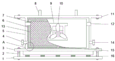
The utility model discloses a supporting and heat-dissipating device of a vehicle power device, which comprises a base, a mounting plate and a heat-dissipating bracket, a plurality of damping springs are fixedly connected above the base, a mounting plate is fixedly connected above the damping springs, bolts are respectively arranged on two sides of the mounting plate, and is connected with a lower base by screw threads, a shell is fixedly connected above the mounting plate and is a hollow shell, a sealing layer is fixedly arranged on the inner wall of the shell, a layer of radiating pipe is fixedly arranged on the inner side of the sealing layer, the bottom of the left side of the shell is fixedly connected with a water inlet which penetrates through the shell and the sealing layer, and is communicated with the radiating pipe, the other side of the water inlet corresponding to the shell is provided with a water outlet, the radiating pipe is characterized in that a partition plate is arranged in the middle of the bottom of the radiating pipe, and a plurality of radiating ports are formed in the two sides of the shell respectively. The utility model discloses in, adopt forced air cooling and water-cooling technique to combine, effectively dispel the heat to vehicle power device, still can carry out the shock attenuation to the battery.
Description
Technical Field
The utility model relates to a vehicle heat abstractor technical field especially relates to a vehicle power device supports heat abstractor.
Background
The new energy electric automobile is used as a new generation of transportation tool, has incomparable advantages of the traditional automobile in the aspects of energy conservation and emission reduction and reduction of dependence of human beings on traditional fossil energy, and the battery is used as a core component of the new energy electric automobile and is important for safe and reliable operation.
However, in the existing new energy automobile, a battery generates a large amount of heat during charging and discharging or working, which easily causes thermal runaway of the battery, and the heat must be dissipated as soon as possible, otherwise the battery is easily expanded violently, even explodes, and serious potential safety hazards are brought.
SUMMERY OF THE UTILITY MODEL
The utility model aims at solving the defects existing in the prior art and providing a vehicle power device supporting and heat radiating device.
In order to achieve the above purpose, the utility model adopts the following technical scheme:
a supporting and heat dissipating device of a vehicle power device comprises a base, a mounting plate and a heat dissipating support, wherein a plurality of damping springs are fixedly connected above the base, a mounting plate is fixedly connected above the damping springs, bolts are respectively arranged on two sides of the mounting plate, the mounting plate is in threaded connection with a lower base, a shell is fixedly connected above the mounting plate, the shell is a hollow shell, a sealing layer is fixedly arranged on the inner wall of the shell, a layer of heat dissipating pipe is fixedly arranged on the inner side of the sealing layer, a water inlet is fixedly connected to the bottom of the left side of the shell, the water inlet penetrates through the shell and the sealing layer and is connected to the heat dissipating pipe in a penetrating manner, a water discharging port is arranged at the other side of the shell corresponding to the water inlet, a partition plate is arranged in the middle of, the improved radiating device comprises a shell and is characterized in that a top plate is fixedly connected to the top of the shell, two ear plates are fixedly connected to the upper portion of the top plate, a radiating support is fixedly mounted in the middle of the inner portion of the shell, a radiating fan is fixedly mounted on the radiating support and supplies air to the front of the shell, and a dust isolating net is arranged on the front of the shell.
As a further description of the above technical solution:
the water inlet and the water outlet are positioned on the same horizontal line and are positioned at the lower side of the radiating pipe, the radiating pipe is divided into a left part and a right part by the partition board, and forced backflow is carried out during radiating.
As a further description of the above technical solution:
and valves are arranged on the water inlet and the water outlet, and the outer sides of the valves are fixedly connected into the water cooling circulation system.
As a further description of the above technical solution:
the sealing layer is made of a silica gel material.
As a further description of the above technical solution:
bolts are also matched on two sides of the top plate, and the length of the bolts on the top plate is smaller than that of the bolts on the mounting plate.
As a further description of the above technical solution:
the cooling fan is provided with a driving box, a motor and the like.
As a further description of the above technical solution:
and a dustproof net is arranged in the heat dissipation port.
The utility model discloses following beneficial effect has:
1. the utility model discloses in utilize forced air cooling and water-cooling technique to combine, can effectively dispel the heat to positions such as car group battery, effectively reduce the temperature of battery during operation, improve the life of battery.
2. The utility model discloses in with the group battery when fixed, simple to operate can carry out the shock attenuation to the group battery moreover, when the vehicle travel, reduces the vibrations of group battery, plays good guard action to the group battery.
3. The utility model discloses among the well water cooling system, outlet and water inlet are located one side, realize forcing the backward flow, have improved water-cooled heat transfer, radiating efficiency, and then hoisting device's heat dispersion.
Drawings
Fig. 1 is a front view of a vehicle power unit support heat sink in accordance with the present invention;
fig. 2 is a side view of a vehicle power unit support heat sink in accordance with the present invention;
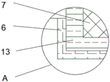
fig. 3 is a partially enlarged schematic view of a portion a in fig. 1 of a supporting and heat dissipating device of a vehicle power unit according to the present invention.
Illustration of the drawings:
1. a base; 2. a bolt; 3. mounting a plate; 4. a water inlet; 5. a housing; 6. a sealing layer; 7. a dust-proof net; 8. an ear plate; 9. a heat dissipation bracket; 10. a heat radiation fan; 11. a top plate; 12. a heat dissipation port; 13. a radiating pipe; 14. a water outlet; 15. a partition plate; 16. a shock absorbing spring.
Detailed Description
The technical solutions in the embodiments of the present invention will be described clearly and completely with reference to the accompanying drawings in the embodiments of the present invention, and it is obvious that the described embodiments are only some embodiments of the present invention, not all embodiments. Based on the embodiments in the present invention, all other embodiments obtained by a person skilled in the art without creative work belong to the protection scope of the present invention.
In the description of the present invention, it should be noted that the terms "center", "upper", "lower", "left", "right", "vertical", "horizontal", "inner", "outer", and the like indicate orientations or positional relationships based on the orientations or positional relationships shown in the drawings, and are only for convenience of description and simplification of description, but do not indicate or imply that the device or element referred to must have a specific orientation, be constructed and operated in a specific orientation, and thus, should not be construed as limiting the present invention; the terms "first," "second," and "third" are used for descriptive purposes only and are not to be construed as indicating or implying relative importance, and furthermore, unless otherwise explicitly stated or limited, the terms "mounted," "connected," and "connected" are to be construed broadly and may be, for example, fixedly connected, detachably connected, or integrally connected; can be mechanically or electrically connected; they may be connected directly or indirectly through intervening media, or they may be interconnected between two elements. The specific meaning of the above terms in the present invention can be understood in specific cases to those skilled in the art.
Referring to fig. 1-3, the present invention provides an embodiment: a supporting and heat dissipating device of a vehicle power device comprises a base 1, a mounting plate 3 and a heat dissipating support 9, wherein a plurality of damping springs 16 are fixedly connected above the base 1, the mounting plate 3 is fixedly connected above the damping springs 16, bolts 2 are respectively arranged on two sides of the mounting plate 3, the lower base 1 is in threaded connection with the upper portion of the mounting plate 3, a shell 5 is fixedly connected above the mounting plate 3, the shell 5 is a hollow shell, a sealing layer 6 is fixedly arranged on the inner wall of the shell 5, a layer of heat dissipating pipe 13 is fixedly arranged on the inner side of the sealing layer 6, a water inlet 4 is fixedly connected to the left bottom of the shell 5, the water inlet 4 penetrates through the shell 5 and the sealing layer 6 and is connected to the heat dissipating pipe 13 in a penetrating way, a water outlet 14 is arranged on the other side of the shell 5 corresponding to the water inlet 4, a partition, 5 top fixedly connected with roof 11 of shell, two otic placodes 8 of roof 11 top fixedly connected with, 5 inside middle fixed mounting of shell have a heat dissipation support 9, and fixed mounting has a radiator fan 10 on the heat dissipation support 9, and radiator fan 10 openly supplies air to shell 5, and shell 5 openly is provided with a dust separation net 7.
The working principle is as follows:
1. when the device is installed in a vehicle, the whole device is positioned below the battery pack, the battery pack is installed between the two ear plates to form rigid fixed connection, and the dust separation net is positioned on the front surface.
2. The water inlets and the water outlets on the two sides are connected to the water cooling circulation system on the outer side, when heat dissipation is carried out, heat generated by the battery pack enters the water cooling system, and after entering from the water inlets, cooling water circulates to the water outlet on the right side from the pipeline on the upper side to be discharged due to the sealing of the partition plate on the lower side.
3. When water circulates, the internal cooling fan rotates, and the heat dissipation ports on the two sides exchange air with external cold air to dissipate heat inside the device and finish heat exchange and heat dissipation work with cooling water.
4. When the vehicle runs, the vehicle vibrates, and the battery pack is upwards transferred through the damping spring, the damping spring deforms, the vibration force is absorbed, and the vibration of the battery pack is reduced.
Finally, it should be noted that: although the present invention has been described in detail with reference to the foregoing embodiments, it will be apparent to those skilled in the art that modifications and variations can be made in the embodiments or in part of the technical features of the embodiments without departing from the spirit and the scope of the invention.
Claims (7)
1. The utility model provides a vehicle power device supports heat abstractor, includes base (1), mounting panel (3), heat dissipation support (9), its characterized in that: the improved structure of the water-cooling pipe is characterized in that a plurality of damping springs (16) are fixedly connected to the upper portion of the base (1), a mounting plate (3) is fixedly connected to the upper portion of the damping springs (16), bolts (2) are respectively arranged on two sides of the mounting plate (3), the base (1) is connected to the lower portion of the threaded connection, a shell (5) is fixedly connected to the upper portion of the mounting plate (3), the shell (5) is a hollow shell, a sealing layer (6) is fixedly arranged on the inner wall of the shell (5), a layer of radiating pipe (13) is fixedly arranged on the inner side of the sealing layer (6), a water inlet (4) is fixedly connected to the bottom of the left side of the shell (5), the water inlet (4) penetrates through the shell (5) and the sealing layer (6) and is connected to the radiating pipe (13) in a penetrating manner, a water outlet (14, shell (5) both sides are provided with a plurality of thermovents (12) respectively, thermovent (12) through connection is to shell (5) inside cavity, shell (5) top fixedly connected with roof (11), two otic placodes (8) of roof (11) top fixedly connected with, fixed mounting has a heat dissipation support (9) in the middle of shell (5) is inside, fixed mounting has a radiator fan (10) on heat dissipation support (9), radiator fan (10) openly supply air to shell (5), shell (5) openly is provided with one and separates dirt net (7).
2. A vehicle power plant support heat sink as recited in claim 1, wherein: the water inlet (4) and the water outlet (14) are positioned on the same horizontal line and are positioned at the lower side of the radiating pipe (13), the radiating pipe (13) is divided into a left part and a right part by the partition plate (15), and forced backflow is performed during heat radiation.
3. A vehicle power plant support heat sink as recited in claim 1, wherein: valves are arranged on the water inlet (4) and the water outlet (14), and the outer sides of the valves are fixedly connected to the water cooling circulation system.
4. A vehicle power plant support heat sink as recited in claim 1, wherein: the sealing layer (6) is made of a silica gel material.
5. A vehicle power plant support heat sink as recited in claim 1, wherein: the bolt (2) is also matched and sleeved on the two sides of the top plate (11), and the length of the bolt (2) on the top plate (11) is smaller than that of the bolt (2) on the mounting plate (3).
6. A vehicle power plant support heat sink as recited in claim 1, wherein: the cooling fan (10) is provided with a driving box and a motor in a matched facility.
7. A vehicle power plant support heat sink as recited in claim 1, wherein: and a dustproof net is arranged in the heat dissipation port (12).
Priority Applications (1)
| Application Number | Priority Date | Filing Date | Title |
|---|---|---|---|
| CN202021231275.3U CN211376773U (en) | 2020-06-30 | 2020-06-30 | Supporting and heat radiating device for vehicle power device |
Applications Claiming Priority (1)
| Application Number | Priority Date | Filing Date | Title |
|---|---|---|---|
| CN202021231275.3U CN211376773U (en) | 2020-06-30 | 2020-06-30 | Supporting and heat radiating device for vehicle power device |
Publications (1)
| Publication Number | Publication Date |
|---|---|
| CN211376773U true CN211376773U (en) | 2020-08-28 |
Family
ID=72173508
Family Applications (1)
| Application Number | Title | Priority Date | Filing Date |
|---|---|---|---|
| CN202021231275.3U Expired - Fee Related CN211376773U (en) | 2020-06-30 | 2020-06-30 | Supporting and heat radiating device for vehicle power device |
Country Status (1)
| Country | Link |
|---|---|
| CN (1) | CN211376773U (en) |
Cited By (1)
| Publication number | Priority date | Publication date | Assignee | Title |
|---|---|---|---|---|
| CN112677824A (en) * | 2021-01-28 | 2021-04-20 | 江苏航运职业技术学院 | Electric automobile battery thermal runaway's protection system with automatic alarm function |
-
2020
- 2020-06-30 CN CN202021231275.3U patent/CN211376773U/en not_active Expired - Fee Related
Cited By (2)
| Publication number | Priority date | Publication date | Assignee | Title |
|---|---|---|---|---|
| CN112677824A (en) * | 2021-01-28 | 2021-04-20 | 江苏航运职业技术学院 | Electric automobile battery thermal runaway's protection system with automatic alarm function |
| CN112677824B (en) * | 2021-01-28 | 2022-03-29 | 江苏航运职业技术学院 | Electric automobile battery thermal runaway's protection system with automatic alarm function |
Similar Documents
| Publication | Publication Date | Title |
|---|---|---|
| CN111244573B (en) | Automobile power battery enhanced heat dissipation device based on vibration energy recovery | |
| CN111129655A (en) | Self-discharge less and cycle number more integrated new energy automobile battery | |
| CN211376773U (en) | Supporting and heat radiating device for vehicle power device | |
| CN214753915U (en) | Quick radiating component for new energy automobile battery management | |
| CN208637490U (en) | A kind of power battery box of electric vehicle for being easy to radiate and install | |
| CN212848577U (en) | A battery package structure for new energy automobile | |
| CN210958057U (en) | Electromechanical integrated motor protector | |
| CN210591472U (en) | Three-system integrated heat dissipation device for hydrogen fuel cell automobile | |
| CN111741639A (en) | Motor controller with waterproof device | |
| CN116345044A (en) | New energy battery protection casing | |
| CN212277300U (en) | Self-discharge less and cycle number more integrated new energy automobile battery | |
| CN214396638U (en) | Protection circuit board for new energy automobile | |
| CN214543944U (en) | Electromechanical antidetonation heat abstractor that uses | |
| CN211106935U (en) | New energy commercial vehicle electric drive system cooling device | |
| CN211792580U (en) | Heat radiator for converter | |
| CN112151713A (en) | Anti-theft battery shell of electric motorcycle and mounting mode | |
| CN112290134A (en) | New energy automobile power battery storage device | |
| CN110730598A (en) | Heat radiator for converter | |
| CN216684072U (en) | Radiator fan convenient to installation | |
| CN114684036B (en) | Protection circuit board for new energy automobile | |
| CN220324591U (en) | Battery pack box structure of electric vehicle | |
| CN220511551U (en) | New energy automobile motor controller casing assembly | |
| CN212033108U (en) | Battery pack capable of simplifying assembly and efficiently dissipating heat | |
| CN221633537U (en) | Water-cooled motor with anti-leakage structure | |
| CN221278097U (en) | Controller of magnetic suspension molecular pump |
Legal Events
| Date | Code | Title | Description |
|---|---|---|---|
| GR01 | Patent grant | ||
| GR01 | Patent grant | ||
| CF01 | Termination of patent right due to non-payment of annual fee | ||
| CF01 | Termination of patent right due to non-payment of annual fee |
Granted publication date: 20200828 |