CN214712076U - Honey falls bag mechanism and multi-functional intelligent honey capsule machine thereof - Google Patents
Honey falls bag mechanism and multi-functional intelligent honey capsule machine thereof Download PDFInfo
- Publication number
- CN214712076U CN214712076U CN202120368557.6U CN202120368557U CN214712076U CN 214712076 U CN214712076 U CN 214712076U CN 202120368557 U CN202120368557 U CN 202120368557U CN 214712076 U CN214712076 U CN 214712076U
- Authority
- CN
- China
- Prior art keywords
- honey
- water
- tray
- capsule
- blowing
- Prior art date
- Legal status (The legal status is an assumption and is not a legal conclusion. Google has not performed a legal analysis and makes no representation as to the accuracy of the status listed.)
- Active
Links
Images


Abstract
The application relates to the field of honey water brewing machines, and discloses a honey capsule dropping mechanism and a multifunctional intelligent honey capsule machine thereof, wherein the honey capsule dropping mechanism comprises a discharging component for placing honey capsules and a puncturing component for puncturing the honey capsules, the multifunctional intelligent honey capsule machine comprises a shell, a water storage mechanism and a honey capsule dropping mechanism arranged in the shell, the water storage mechanism comprises a water storage tank, water pump motor and heating unit, the storage water tank, water pump motor and heating unit all set up on the casing, the income water end of water pump motor leads to pipe and links to each other with the storage water tank, the play water end of water pump motor leads to pipe and links to each other with heating unit, honey falls bag mechanism including the blowing subassembly that is used for placing the honey capsule and the puncture subassembly that is used for pricking the honey capsule, heating unit's play water end leads to pipe carries water to the blowing subassembly in, the below of blowing subassembly is equipped with the drain pipe. This application has the effect that improves the efficiency of dashing of honey water.
Description
Technical Field
The application relates to the field of honey water brewing machines, in particular to a honey falling mechanism and a multifunctional intelligent honey capsule machine thereof.
Background
At present, the honey water weight-reducing method is a popular weight-reducing method. The fatty acid contained in honey can promote intestinal tract movement, and the abundant vitamins and minerals have the functions of regulating intestines and stomach, removing toxin in vivo and improving constipation.
In the related art, when the honey water is prepared, people need to scoop a proper amount of honey with a spoon or pour a proper amount of honey from a bottle into a cup, then pour warm water into the cup, and stir and prepare the honey water with the spoon.
To the correlation technique among the above-mentioned, the utility model discloses the people think when dashing the honey water, need artifical manual honey and the water of adding to dash and transfer, have the defect that dashes the honey water inefficiency.
SUMMERY OF THE UTILITY MODEL
In order to improve the defect that the manual brewing honey water is inefficient, the application provides a honey falls bag mechanism and multi-functional intelligent honey capsule machine thereof.
The application provides a honey falls bag mechanism adopts following technical scheme to obtain:
the utility model provides a honey falls bag mechanism, is including the blowing subassembly that is used for placing the honey capsule and be used for the puncture subassembly that punctures the honey capsule, puncture subassembly includes pjncture needle and the cylinder that the drive pjncture needle impales the honey capsule, the cylinder is connected fixedly with the casing, the pjncture needle links to each other with the output of cylinder, the inside cavity of pjncture needle, the pjncture needle is linked together with the water pipe, the one end that the cylinder was kept away from to the pjncture needle has seted up the wash port on the lateral wall, the below of blowing subassembly is equipped with the drain pipe.
Through the technical scheme, when the honey water is brewed, the cylinder drives the puncture needle to penetrate and puncture the honey capsules, then the puncture needle is driven to ascend, at the moment, the heated water is pumped into the puncture needle through the water pipe, at the moment, the water is sprayed out at a high speed through the drain hole, the water is mixed with the honey to form the honey water, and the honey water is brewed. After a honey capsule finishes using, can change the honey capsule in the blowing subassembly to the brewing next cup of honey water, easy operation is convenient.
Preferably: the drainage holes are arranged in a plurality and are distributed along the periphery of the puncture needle.
Through above-mentioned technical scheme, the during operation, high-speed blowout in water from a plurality of drainage mouths to with honey intensive mixing, be favorable to improving efficiency and the degree of consistency that the honey water was mixed.
Preferably: the blowing subassembly includes bracket, blowing board and deposits the feed cylinder, bracket fixed connection is on shells inner wall, the blowing board slides and sets up on the bracket, first blowing groove has been seted up on the blowing board, the drain pipe is connected in the below of blowing board and is linked together with first blowing groove, deposit the feed cylinder both ends and link up, and the interior wall connection of one end and casing, the other end laminates mutually with the blowing board, the one end that the blowing board was kept away from to the deposit feed cylinder links to each other with the casing, and establishes to the charge door.
Through above-mentioned technical scheme, during the use, the operator earlier puts into a plurality of honey capsules in proper order and deposits the feed cylinder, then removes the blowing board for first blowing groove removes the below of depositing the feed cylinder, and the honey capsule that is located the below this moment falls into first blowing groove under the action of gravity in, removes the blowing board to initial position again after that, and the one end shutoff that the charge door was kept away from to the feed cylinder is stopped up with the blowing board this moment. Deposit the setting of feed cylinder, be favorable to the operator once only to deposit a plurality of honey capsules in the feed cylinder to realize the material loading through removing the flitch, easy operation is convenient.
Preferably: the both sides of casing are seted up and are supplied the logical groove that the blowing board wore to establish, the one end of blowing board is connected with the push rod, logical groove is worn to establish by the push rod.
Through above-mentioned technical scheme, the operator can promote the blowing board through promoting the push rod and remove, when the vacant shell that will pass through the honey capsule of use takes off from first blowing inslot as needs, the operator passes through the push rod with the blowing board and passes out in the casing to the operator will pass through the vacant shell of honey capsule of use and take off from first blowing inslot. And the operator can take the entire discharge plate out of the housing to clean the first discharge chute.
Preferably: the filter cloth is arranged in the liquid outlet pipe, and one end of the liquid outlet pipe, which is far away from the discharging plate, is bent along the horizontal direction.
Through the technical scheme, before the honey water flows into the water cup from the liquid outlet pipe, the honey water is filtered by the filter cloth, so that foams in the honey water are filtered; and the operator can be with the cup wall of drinking cup and the bottom of drain pipe laminating mutually to honey water flows down slowly along the cup wall, has reduced because of the difference in height and has leaded to the honey water to produce the possibility of foam when flowing into the drinking cup, thereby is favorable to improving the entry feel of honey water.
Preferably: the discharging assembly comprises a tray, a second discharging groove is formed in the tray, and the liquid outlet pipe is connected below the tray and communicated with the second discharging groove.
Through the technical scheme, before work, an operator puts the honey capsules filled with honey into the second feeding groove. When the honey water needs to be mixed, the cylinder drives the puncture needle to move towards the honey capsule until the puncture needle penetrates through the honey capsule, then the puncture needle is driven to ascend, at the moment, the heated water is pumped into the puncture needle through the water pipe, the water is sprayed out at a high speed through the drain hole, the water is mixed with the honey to form the honey water, and the honey water is mixed.
Preferably: the second discharging groove is provided with a plurality of discharging grooves, the plurality of discharging grooves are arranged on the tray to form a circle, and a driving piece used for driving the tray to rotate is arranged in the shell.
Through above-mentioned technical scheme, before the work, the operator can all place a honey capsule reserve towards in a plurality of second blow-off tanks to after honey in a honey capsule is used up, it is rotatory through driving piece drive tray, thereby make reserve honey capsule can use in succession on the tray.
Preferably: the outer side of tray is equipped with the latch along the outer peripheral edges, the below of tray in the casing is equipped with the support frame, the casing rotates with the support frame and sets up, the driving piece includes first motor and the gear of coaxial coupling in the axis of rotation of first motor, the breach has been preset on the gear, gear and latch intermeshing.
Through above-mentioned technical scheme, when needs drive tray is rotatory, first motor work to drive gear coaxial rotation, gear and latch meshing transmission this moment, thereby it is rotatory to drive the tray, until the breach department of latch rotation to gear, the latch takes off with the gear and leaves, and the tray stops rotatoryly, and the honey capsule that treats to use this moment removes the below to the pjncture needle, so that continue to dash and transfer honey water.
Preferably: the support frame is towards one side fixedly connected with spliced pole of tray, the tray is worn to establish coaxially to the spliced pole, the spliced pole is worn to establish the articulated dog that is provided with of one end of tray, the dog is laminated mutually with one side that the tray deviates from the support frame.
Through above-mentioned technical scheme, when needs cleared up the tray, the operator can be rotatory round the articulated department between dog and the spliced pole with the dog for the dog is changed into vertical state from the horizontality, and the operator moves the tray along the spliced pole rebound after that, breaks away from completely until tray and spliced pole, thereby realizes dismantling the tray. Wait the operator and wear to establish dog and spliced pole again with the tray after with the tray clean up to with the dog round the articulated department rotation between dog and the spliced pole, make the dog rotatory to the horizontality, and laminate mutually with the tray. Adopt the mode of dismantling the connection between tray and the support frame, the operator of being convenient for regularly dismantles the tray and gets off and clear up to be favorable to improving the cleanliness of tray, and then be favorable to improving the safety and sanitation degree.
The application still provides a pair of multi-functional intelligent honey capsule machine, adopts following technical scheme to obtain:
the utility model provides a multi-functional intelligent honey capsule machine, falls bag mechanism including casing, water storage mechanism, the honey of setting in the casing, water storage mechanism includes storage water tank, water pump motor and heating unit, storage water tank, water pump motor and heating unit all set up on the casing, the income water end of water pump motor leads to pipe and links to each other with the storage water tank, the play water end of water pump motor leads to pipe and links to each other with the heating unit, honey falls bag mechanism including the blowing subassembly that is used for placing the honey capsule and is used for the puncture subassembly that punctures the honey capsule, the play water end of heating unit leads to pipe carries water to the blowing subassembly in, the below of blowing subassembly is equipped with the drain pipe.
Through above-mentioned technical scheme, when dashing and concocting honey water, the operator places the drinking cup in the below of drain pipe, has put the honey capsule that holds honey in the blowing subassembly, pierces the honey capsule through the puncture subassembly, and meanwhile, water pump motor takes out water from the storage water tank, and water mixes with honey again after the heating of heating element, forms the honey water, and the honey water flows in the drinking cup from the drain pipe at last. By the arrangement, the automatic brewing of the honey water is realized, and the efficiency of brewing the honey water is improved.
In summary, the present application includes at least one of the following beneficial technical effects:
1. the automatic blending of the honey water is realized, and the blending efficiency of the honey water is improved;
2. when the honey water flows into the water cup, the foam filtering effect is achieved on the honey water, and therefore the quality of the honey water is improved.
Drawings
FIG. 1 is a schematic structural diagram of the internal structure of a honey encapsulating machine embodying the opening and closing of the door in the embodiment 1 of the present application.
Fig. 2 is a schematic structural view for embodying a water storage mechanism in embodiment 1 of the present application.
Fig. 3 is a schematic structural view for embodying a filter cloth in the liquid outlet pipe.
Figure 4 is a schematic structural diagram of the internal structure of the honey encapsulating machine for embodying the opening and closing of the door in the embodiment 2 of the application.
Fig. 5 is an enlarged view of a portion a in fig. 5.
Fig. 6 is a schematic structural view for showing a screw hole formed below the second chute in the tray in embodiment 2 of the present application.
Reference numerals: 1. a housing; 11. a feed inlet; 12. a through groove; 13. opening and closing the door; 2. a water storage mechanism; 21. a water storage tank; 22. a water pump motor; 23. a heating unit; 24. a water pipe; 3. a honey bag dropping mechanism; 31. puncturing needle; 311. a drain hole; 32. a cylinder; 33. a bracket; 34. a material placing plate; 341. a push rod; 342. a first discharge chute; 35. a material storage barrel; 36. a tray; 361. a second discharge chute; 362. clamping teeth; 363. a threaded hole; 364. an elastic wiper blade; 37. a gear; 371. a notch; 38. a first motor; 39. a support frame; 391. connecting columns; 392. a stopper; 4. a liquid outlet pipe; 41. and (4) a filter cloth.
Detailed Description
The present application is described in further detail below with reference to figures 1-6.
For this application embodiment discloses a honey falls bag mechanism and multi-functional intelligent honey capsule machine thereof. The honey capsule is formed by packaging honey in plastic, so that the honey capsule is convenient to use and is sanitary and convenient.
Referring to fig. 1, the multifunctional intelligent honey capsule machine comprises a shell 1, a water storage mechanism 2 and a honey capsule dropping mechanism 3 arranged in the shell 1. The open end has been seted up to one side of casing 1, and open end department is equipped with switch door 13, and one side of switch door 13 is articulated with casing 1, and the open end is closed through switch door 13. The honey capsule falling mechanism 3 comprises a discharging component for placing honey capsules and a puncturing component for puncturing the honey capsules, the water storage mechanism 2 conveys water into the discharging component through a water pipe 24, and a liquid outlet pipe 4 is arranged below the discharging component. When the honey water storage device is used, honey capsules are stored in the discharging assembly, then the honey capsules penetrate through the puncturing assembly, the water storage mechanism 2 adds water into the discharging assembly, the water and honey are mixed at the moment to form honey water, and the honey water flows into a water cup through the liquid outlet pipe 4. Through this multi-functional intelligent honey capsule machine transfer with form the honey water, it is efficient than artifical manual mediation honey water.
Example 1:
referring to fig. 2, the water storage mechanism 2 includes a water storage tank 21, a water pump motor 22 and a heating unit 23, the water storage tank 21 is disposed on the housing 1, a water inlet end of the water pump motor 22 is connected to the water storage tank 21 through a water pipe 24, the heating unit 23 is a heating tank, a heating pipe is disposed in the heating tank, a water outlet end of the water pump motor 22 is connected to the heating tank through the water pipe 24, and a water outlet end of the heating tank delivers water to the material dispensing assembly through the water pipe 24. When the water pump motor 22 works and pumps water into the heating tank, the heating pipe in the heating tank heats the water to a constant temperature, and the constant temperature is set to be fifty degrees centigrade.
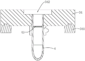
Referring to fig. 1, the discharging assembly includes a bracket 33, a discharging plate 34, and a material storage barrel 35, the bracket 33 is fixedly connected to the inner wall of the housing 1, a sliding rail is disposed on one side of the bracket 33 facing the discharging plate 34, a sliding groove is disposed on one side of the discharging plate 34 facing the bracket 33, the sliding rail is slidably disposed in the sliding groove, and the discharging plate 34 and the bracket 33 are slidably connected. Through grooves 12 for the feeding plates 34 to penetrate are formed in two sides of the shell 1, one end of each feeding plate 34 is connected with a push rod 341, and the push rod 341 passes through the through grooves 12. The discharging plate 34 is provided with a first discharging groove 342, the liquid outlet pipe 4 is positioned below the discharging plate 34 and is in threaded connection with the discharging plate 34, and the liquid outlet pipe 4 is communicated with the first discharging groove 342. The two ends of the material storage barrel 35 are communicated, the material storage barrel 35 is positioned above the material placing plate 34, one end of the material storage barrel is fixedly welded with the inner wall, close to the top, of the shell 1, the other end of the material storage barrel is attached to the material placing plate 34, and the top of the shell 1 is provided with a material inlet 11 communicated with the material storage barrel 35.
Referring to fig. 1, during the use, the operator places a plurality of honey capsules in storage cylinder 35, and then the operator moves blowing board 34 through push rod 341 for first blowing groove 342 moves to the below of storage cylinder 35, and at this moment, the honey capsule that is located the bottommost in the blowing cylinder has fallen into first blowing groove 342 under the action of gravity, and then the operator passes blowing board 34 to initial position again, and the material loading is convenient.
Referring to fig. 1, the puncture assembly includes a puncture needle 31 and a cylinder 32, the cylinder 32 and the puncture needle 31 may be disposed above the discharging plate 34, a base of the cylinder 32 is fixedly connected to the inside of the top of the housing 1, the puncture needle 31 is fixedly connected to an output end of the cylinder 32, and the puncture needle 31 corresponds to the position of the first discharging groove 342 in a vertical direction. The puncture needle 31 is hollow, one end of the water pipe 24 far away from the heating tank is communicated with the puncture needle 31, a plurality of drainage holes 311 are arranged on the side wall of one end of the puncture needle 31 far away from the air cylinder 32, and the drainage holes 311 are distributed along the periphery of the puncture needle 31.
Referring to fig. 1, when the honey capsule carried in the first discharging groove 342 moves to the lower part of the puncture needle 31, the air cylinder 32 drives the puncture needle 31 to descend until the puncture needle 31 penetrates through the punctured honey capsule, then the air cylinder 32 drives the puncture needle 31 to ascend again, at this time, heated water is pumped into the puncture needle 31 through the water pipe 24, the water is ejected at a high speed through the plurality of water discharging holes 311, the water is mixed with honey to form honey water, and the honey water is brewed.
Referring to fig. 3, finally, the honey water flows into the cup through the outlet pipe 4. Be equipped with filter cloth 41 in the drain pipe 4, and the one end of drain pipe 4 keeping away from drain plate 34 is crooked along the horizontal direction, before connecing the honey water, the operator places the drinking cup in the below of drain pipe 4 to make the inside wall of drinking cup and the one end that drain pipe 4 kept away from drain plate 34 be close to. When the honey water flows out of the liquid outlet pipe 4, the honey water is filtered by the filter cloth 41, so that the foam in the honey water is filtered, and the taste of the honey water is improved; and the honey water flows down along the cup wall when flowing into the water cup, so that the possibility of splashing in the process of flowing the honey water into the cup is reduced.
The implementation principle of the multi-functional intelligent honey capsule machine of this application embodiment 1 does: when the honey water needs to be prepared, the operator moves the discharging plate 34 through the push rod 341, so that the first discharging groove 342 moves to the lower part of the storage cylinder 35, at the moment, a honey capsule falls into the first discharging groove 342, and then the operator moves the discharging plate 34 to the initial position. At this time, the discharging plate 34 closes the opening below the storage cylinder 35 again, and the first discharging groove 342 corresponds to the vertical position of the puncture needle 31. Then, the cylinder 32 drives the puncture needle 31 to penetrate through and puncture the honey capsule, meanwhile, the water pump motor 22 pumps the water in the water storage tank 21 into the heating tank to be heated, and then the heated water is pumped into the puncture needle 31, at the moment, the cylinder 32 drives the puncture needle 31 to ascend, so that the puncture needle 31 stays in the honey capsule, the water is ejected at a high speed through the water outlet hole 311, and the honey water is formed after the water and the honey are fully mixed. Finally, the honey water flows into the water cup through the liquid outlet pipe 4.
After the honey capsules in the first discharging groove 342 are used, an operator firstly unscrews the liquid outlet pipe 4 from the discharging plate 34, and pushes the discharging plate 34 out of the shell 1 through the push rod 341, so that the operator can take out the used honey capsules from the first discharging groove 342 and then move the discharging plate 34 into the shell 1. When the first discharging groove 342 and the filter cloth 41 need to be cleaned, an operator can unscrew the liquid outlet pipe 4 from the discharging plate 34, push the whole discharging plate 34 out of the casing 1, and respectively clean the first discharging groove 342 and the filter cloth 41.
Example 2:
referring to fig. 4 and 5, different from embodiment 1, the emptying assembly includes a circular tray 36, the outer side of the tray 36 is provided with a latch 362 along the outer periphery, a support 39 is arranged below the tray 36 in the casing 1, and the support 39 is fixedly connected with the inner wall of the casing 1. One side of the supporting frame 39 facing the tray 36 is welded with a connecting column 391, the connecting column 391 coaxially penetrates through the tray 36, one end of the connecting column 391 penetrating through the tray 36 is hinged with a stopper 392, the stopper 392 is in interference fit with the connecting column 391, the stopper 392 is perpendicular to the connecting column 391, and the stopper 392 is attached to one side of the tray 36 departing from the supporting frame 39. A driving member for driving the tray 36 to rotate is arranged in the housing 1, and the driving member includes a first motor 38 and a gear 37, and the gear 37 is coaxially connected with a rotating shaft of the first motor 38. Notches 371 are pre-formed in gear 37 and gear 37 engages with latch 362.
Referring to fig. 5 and 6, a plurality of second discharging grooves 361 are formed in the tray 36, the number of the second discharging grooves 361 may be four, six, or eight, in this embodiment, four placing grooves are provided, and the four second discharging grooves 361 are distributed along the center of the tray 36 and form a circle. The bottom of the tray 36 is provided with a threaded hole 363 below each second discharging groove 361, and the threaded holes 363 are communicated with the second discharging grooves 361. One of the second discharging grooves 361 vertically corresponds to the puncture needle 31 up and down, and the liquid outlet pipe 4 is connected in a threaded hole 363 below the second discharging groove 361 in a threaded manner.
In operation, an operator places a honey capsule in each second chute 361. When the honey water is mixed, the air cylinder 32 drives the puncture needle 31 to penetrate through the honey capsule, meanwhile, the heated water is pumped into the puncture needle 31 through the water pipe 24, at the moment, the air cylinder 32 drives the puncture needle 31 to ascend, so that the puncture needle 31 is stopped in the honey capsule, the water is ejected at a high speed through the drain hole 311, and the honey water is formed after the water and the honey are fully mixed. Finally, the honey water flows into the water cup through the liquid outlet pipe 4.
Referring to fig. 4 and 5, after a honey capsule in the second feeding groove 361 is used, the first motor 38 drives the gear 37 to rotate, the gear 37 is in meshed transmission with the latch 362, so that the tray 36 rotates until the latch 362 rotates to the notch 371 of the gear 37, at this time, the tray 36 stops rotating, the first motor 38 stops working, the honey capsule to be used is contained and moves to the position below the puncture needle 31, and an operator unscrews the liquid outlet pipe 4 from the tray 36 and adjusts the installation position, so that the honey capsule machine can be continuously and continuously used.
When all of the honey capsules on the tray 36 have been used, the operator removes the package of honey capsules and replaces them with new ones. When the tray 36 needs to be replaced after long-term use, the operator rotates the stopper 392 around the hinged position of the stopper 392 and the connecting column 391 to enable the stopper 392 and the connecting column 391 to be kept in a vertical state, then the operator supports the tray 36 upwards to enable the tray 36 to be separated from the connecting column 391, so that the tray 36 is taken down from the supporting frame 39, and after the operator cleans the tray 36, the tray 36 is installed on the supporting frame 39 again.
Referring to fig. 4 and 5, a cleaning assembly is disposed in the housing 1 above each second discharging groove 361 on the tray 36, the cleaning assembly includes a plurality of elastic blades 364, the number of the elastic blades 364 is four, the elastic blades 364 are made of rubber, the four elastic blades 364 are adhered to the tray 36, and the four elastic blades 364 are uniformly disposed along the periphery of the opening of the second discharging groove 361. When the air cylinder 32 drives the puncture needle 31 to ascend, so that the puncture needle 31 is separated from the second discharging groove 361, the outer side wall of the puncture needle 31 is in contact with the elastic scraping blade 364, the elastic scraping blade 364 scrapes the honey adhered to the outer side of the puncture needle 31, and the puncture needle 31 is cleaned.
The implementation principle of the multi-functional intelligent honey capsule machine of embodiment 2 of this application is: when the honey bee honey water dispenser is used, the air cylinder 32 drives the puncture needle 31 to penetrate and puncture a honey capsule in the second discharging groove 361, meanwhile, the heated water is pumped into the puncture needle 31 through the water pipe 24, the air cylinder 32 drives the puncture needle 31 to ascend at the moment, the puncture needle 31 is stopped in the honey capsule, water is ejected at a high speed through the water discharging hole 311, and after the water and honey are fully mixed, honey water is formed. Finally, the honey water flows into the water cup through the liquid outlet pipe 4. After the honey capsule in the second discharging groove 361 is used, the first motor 38 drives the gear 37 to rotate, the gear 37 is in meshing transmission with the latch 362, so that the tray 36 rotates until the latch 362 rotates to the notch 371 of the gear 37, the tray 36 stops rotating at the moment, the first motor 38 stops working, the honey capsule to be used is contained and moves to the lower part of the puncture needle 31, and an operator unscrews the liquid outlet pipe 4 from the tray 36 and adjusts the installation position, so that the honey capsule machine can be continuously and continuously used.
The present embodiment is only for explaining the present application, and it is not limited to the present application, and those skilled in the art can make modifications of the present embodiment without inventive contribution as needed after reading the present specification, but all of them are protected by patent law within the scope of the claims of the present application.
Claims (10)
1. The utility model provides a honey falls bag mechanism which characterized in that: including the blowing subassembly that is used for placing the honey capsule and be used for the puncture subassembly that punctures the honey capsule, puncture subassembly includes pjncture needle (31) and drive pjncture needle (31) and impales cylinder (32) of honey capsule, cylinder (32) are connected fixedly with casing (1), pjncture needle (31) link to each other with the output of cylinder (32), pjncture needle (31) inside cavity, pjncture needle (31) are linked together with water pipe (24), wash port (311) have been seted up on the lateral wall of the one end of cylinder (32) is kept away from in pjncture needle (31), the below of blowing subassembly is equipped with drain pipe (4).
2. A honey pocket dropping mechanism according to claim 1, characterized in that: the number of the water drainage holes (311) is multiple, and the water drainage holes (311) are distributed along the periphery of the puncture needle (31).
3. A honey pocket dropping mechanism according to claim 2, characterized in that: the blowing subassembly includes bracket (33), blowing board (34) and storage cylinder (35), bracket (33) fixed connection is on casing (1) inner wall, blowing board (34) slide and set up on bracket (33), first blowing groove (342) have been seted up on blowing board (34), drain pipe (4) are connected in the below of blowing board (34) and are linked together with first blowing groove (342), storage cylinder (35) both ends link up, and the interior wall connection of one end and casing (1), and the other end laminates with blowing board (34), the one end that storage cylinder (35) kept away from blowing board (34) links to each other with casing (1), and establishes to charge door (11).
4. A honey pocket dropping mechanism according to claim 3, characterized in that: through grooves (12) for the material placing plates (34) to penetrate through are formed in the two sides of the shell (1), one ends of the material placing plates (34) are connected with push rods (341), and the through grooves (12) are formed in the push rods (341) in a penetrating mode.
5. A honey pocket dropping mechanism according to claim 1, characterized in that: be equipped with filter cloth (41) in drain pipe (4), the one end that drain pipe (4) kept away from flitch (34) is crooked along the horizontal direction.
6. A honey pocket dropping mechanism according to claim 1, characterized in that: the discharging assembly comprises a tray (36), a second discharging groove (361) is formed in the tray (36), and the liquid outlet pipe (4) is connected below the tray (36) and communicated with the second discharging groove (361).
7. A honey pocket dropping mechanism according to claim 6, characterized in that: the second discharging grooves (361) are arranged in a plurality, the second discharging grooves (361) are arranged on the tray (36) to form a circle, and a driving piece used for driving the tray (36) to rotate is arranged in the shell (1).
8. A honey pocket dropping mechanism according to claim 7, characterized in that: the outside of tray (36) is equipped with latch (362) along the outer peripheral edges, the below of tray (36) is equipped with support frame (39) in casing (1), casing (1) rotates with support frame (39) and sets up, the driving piece includes first motor (38) and coaxial coupling gear (37) in the axis of rotation of first motor (38), breach (371) have been preset on gear (37), gear (37) and latch (362) intermeshing.
9. A honey pocket dropping mechanism according to claim 8, characterized in that: one side of the support frame (39) facing the tray (36) is fixedly connected with a connecting column (391), the connecting column (391) coaxially penetrates through the tray (36), one end of the connecting column (391) penetrating through the tray (36) is hinged with a stop block (392), and the stop block (392) is attached to one side of the tray (36) departing from the support frame (39).
10. A multi-functional intelligent honey capsule machine of mechanism falls to honey of using claim 1 or 9 characterized by: including casing (1), water storage mechanism (2), set up honey in casing (1) and fall bag mechanism (3), water storage mechanism (2) are including storage water tank (21), water pump motor (22) and heating element (23), storage water tank (21), water pump motor (22) and heating element (23) all set up on casing (1), the income water end of water pump motor (22) passes through water pipe (24) and links to each other with storage water tank (21), the play water end of water pump motor (22) passes through water pipe (24) and links to each other with heating element (23), the play water end of heating element (23) leads to pipe (24) and carries water to the blowing subassembly in.
Priority Applications (1)
| Application Number | Priority Date | Filing Date | Title |
|---|---|---|---|
| CN202120368557.6U CN214712076U (en) | 2021-02-06 | 2021-02-06 | Honey falls bag mechanism and multi-functional intelligent honey capsule machine thereof |
Applications Claiming Priority (1)
| Application Number | Priority Date | Filing Date | Title |
|---|---|---|---|
| CN202120368557.6U CN214712076U (en) | 2021-02-06 | 2021-02-06 | Honey falls bag mechanism and multi-functional intelligent honey capsule machine thereof |
Publications (1)
| Publication Number | Publication Date |
|---|---|
| CN214712076U true CN214712076U (en) | 2021-11-16 |
Family
ID=78588674
Family Applications (1)
| Application Number | Title | Priority Date | Filing Date |
|---|---|---|---|
| CN202120368557.6U Active CN214712076U (en) | 2021-02-06 | 2021-02-06 | Honey falls bag mechanism and multi-functional intelligent honey capsule machine thereof |
Country Status (1)
| Country | Link |
|---|---|
| CN (1) | CN214712076U (en) |
-
2021
- 2021-02-06 CN CN202120368557.6U patent/CN214712076U/en active Active
Similar Documents
| Publication | Publication Date | Title |
|---|---|---|
| CN113773905A (en) | Be used for animal fat production to smelt device with stewing | |
| CN113951520B (en) | Production device for Chinese yam pulp beverage | |
| CN214712076U (en) | Honey falls bag mechanism and multi-functional intelligent honey capsule machine thereof | |
| CN111659174B (en) | Liquid medicine filter equipment with automatic sediment function of arranging | |
| CN113080728A (en) | Household flour stirring device | |
| CN112790612A (en) | Honey falls bag mechanism and multi-functional intelligent honey capsule machine thereof | |
| CN212269421U (en) | Continuous large-batch milk tea filling equipment | |
| CN207430795U (en) | A kind of Chinese herbal medicinal high-efficiency convenient for discharge cleans impurity removing device | |
| CN108541981A (en) | A kind of acanthopore equipment of melon and fruit based food | |
| CN111659175B (en) | Dregs of a decoction filter equipment | |
| CN110292975B (en) | A equipment is prepared to root of kudzu vine powder for health care medicine preparation | |
| CN208493374U (en) | More medium filter is used in a kind of middle water factory's sewage treatment recycling | |
| CN111407660A (en) | Automatic pharmaceutical equipment for traditional Chinese medicine | |
| CN218339566U (en) | Animal remedy oral liquid preparation facilities | |
| CN116271966B (en) | Purslane extraction device and method | |
| CN213326659U (en) | Metering and packaging device for metal cleaning agent | |
| CN214047468U (en) | Dosing unit is used in lobster processing | |
| CN220715463U (en) | Liquid sugar dissolving device | |
| CN209863407U (en) | Beverage brewing device and automatic beverage machine | |
| CN220224113U (en) | Solid-liquid separation device for oil preparation by water substitution method | |
| CN219252801U (en) | Crushing device for livestock and poultry manure treatment | |
| CN215077522U (en) | Sandwich pot | |
| CN218010383U (en) | Complete equipment for extracting and producing natural herbal medicine | |
| CN218741473U (en) | Herbal pieces-boiling equipment | |
| CN217242612U (en) | Stuffing making machine for food processing |
Legal Events
| Date | Code | Title | Description |
|---|---|---|---|
| GR01 | Patent grant | ||
| GR01 | Patent grant |