CN214696962U - Construction is with platform of unloading - Google Patents
Construction is with platform of unloading Download PDFInfo
- Publication number
- CN214696962U CN214696962U CN202120799569.4U CN202120799569U CN214696962U CN 214696962 U CN214696962 U CN 214696962U CN 202120799569 U CN202120799569 U CN 202120799569U CN 214696962 U CN214696962 U CN 214696962U
- Authority
- CN
- China
- Prior art keywords
- plate
- backplate
- guard
- bottom plate
- folding
- Prior art date
- Legal status (The legal status is an assumption and is not a legal conclusion. Google has not performed a legal analysis and makes no representation as to the accuracy of the status listed.)
- Active
Links
Images


Abstract
The utility model provides a platform of unloading for construction relates to building construction equipment technical field, including two supporting beam and the bottom plate of being connected with two supporting beam, the bottom plate upper surface is connected with first backplate, second backplate and third backplate, first backplate and third backplate set up relatively and are parallel with a supporting beam, the second backplate is perpendicular with first backplate and third backplate and is connected, the top of first backplate is fixedly connected with first folded sheet, the top of first folded sheet articulates and is connected with the second folded sheet, be provided with automatic telescopic link between first folded sheet and the second folded sheet, the both ends of automatic telescopic link articulate with first folded sheet and second folded sheet respectively and are connected; be provided with the baffle between first backplate and the third backplate, the baffle is on a parallel with first backplate to can dismantle with the bottom plate and be connected, when the platform top of unloading among the solution prior art does not have the protection and leads to tower crane handling material, the material causes the problem of collision and damage to constructor easily.
Description
Technical Field
The utility model belongs to the technical field of the construction equipment, specifically provide a platform of unloading for construction.
Background
The unloading platform is various temporary operation platforms and operation frames which are usually erected on a construction site and is generally used for material turnover. The unloading platform is divided into a movable unloading platform, a floor type unloading platform and a cantilever type unloading platform, after construction of a certain layer of structure of a high-rise building is completed, templates, steel pipes, equipment and the like of a concrete structure of a construction floor need to be lifted to the outside of a floor under construction, the materials and the equipment cannot be transported away in the building, the unloading platform needs to be built so that the materials can be lifted to the unloading platform by a tower crane and then transported to a construction site, and the unloading platform is used as a working platform for providing material transfer and temporary storage in the construction process.
The top of the conventional discharging platform is not protected, when the conventional discharging platform is used, when a tower crane hoists materials to be close to the discharging platform, a constructor needs to stand on the discharging platform to support the materials to avoid the materials from shaking or colliding or interfering with a fence of the discharging platform due to inaccurate position, so that the materials cannot be smoothly placed on the discharging platform; when the tower crane lifts the material on the unloading platform, a constructor is also required to construct a lifting hook of the tower crane on the material to assist the tower crane to lift the material vertically; when the material on the platform of unloading is transported in cooperation with the tower crane, the material easily causes collision and scratches to constructors, threatens the life safety of the constructors.
Accordingly, there is a need in the art for a discharge platform for construction that addresses the above-mentioned problems.
SUMMERY OF THE UTILITY MODEL
The utility model provides a construction is with platform of unloading solves the platform top of unloading among the prior art and does not have when the protection leads to tower crane handling material, and the material causes the problem of collision and damage to constructor easily.
The technical scheme of the utility model is realized like this: the discharging platform for building construction comprises two supporting beams and a bottom plate connected with the two supporting beams, wherein a first protection plate, a second protection plate and a third protection plate are connected to the upper surface of the bottom plate, the first protection plate and the third protection plate are oppositely arranged and are parallel to the supporting beams, the second protection plate is perpendicular to and connected with the first protection plate and the third protection plate, a first folding plate is fixedly connected to the top of the first protection plate, a second folding plate is arranged on one side, close to the third protection plate, of the first folding plate, the second folding plate is hinged to the top of the first folding plate, an automatic telescopic rod is arranged between the first folding plate and the second folding plate, and two ends of the automatic telescopic rod are hinged to the first folding plate and the second folding plate respectively; a baffle is arranged between the first guard plate and the third guard plate, and the baffle is parallel to the first guard plate and is detachably connected with the bottom plate.
The technical effect of the scheme is as follows: by arranging the first folding plate and the second folding plate, when constructors receive materials or feed materials, the automatic telescopic rod is controlled to extend to drive the second folding plate to rotate upwards for unfolding, and the second folding plate forms protection at the top of the constructors, so that the heads of the constructors are prevented from being damaged by the materials; through setting up the baffle, the space of platform of unloading is divided into two to the baffle for constructor provides the space of standing for constructor can stand and connect material or pay-off in the space that baffle and first backplate formed, avoids the material to cause collision or fish tail to constructor's health, improves the security of the platform use of unloading.
In the preferable technical scheme of the unloading platform for building construction, the vertical section of the baffle is in an inverted T shape, the bottom plate is provided with a chute with a C-shaped vertical section, the chute extends along the length direction of the supporting beam, and the baffle is in sliding connection with the bottom plate through the chute.
The technical effect of the scheme is as follows: the baffle plate is connected with the bottom plate in a sliding mode, on one hand, stable connection of the baffle plate and the bottom plate is guaranteed, substantial protection is formed for constructors, on the other hand, when materials on the unloading platform are conveyed into floors, the baffle plate can be detached from the bottom plate in a sliding mode, space is provided for conveying the materials, and operation is convenient.
In the above-mentioned construction is with preferred technical scheme of platform of unloading, a supporting beam is the I-steel, the bottom of bottom plate is provided with the walking wheel, the walking wheel is striden and is located the web both sides of I-steel, contact with the bottom pterygoid lamina of I-steel, a supporting beam's end is provided with the backstop piece, driving motor is installed to the bottom of bottom plate, driving motor's output installs the gear, a supporting beam's bottom is provided with the rack along its length direction, the gear with the rack meshes mutually.
The technical effect of the scheme is as follows: the driving motor drives the gear to rotate along the rack, the bottom plate is driven to move along the supporting beam, the discharging platform can move to the floor, and materials on the discharging platform can be conveniently carried to the floor by constructors.
In the preferable technical scheme of the discharging platform for building construction, the third guard plate is hinged to the bottom plate, the side, close to each other, of the third guard plate and the side, close to each other, of the second guard plate are respectively provided with the mounting rings distributed at intervals in the vertical direction, the mounting rings of the third guard plate and the second guard plate are distributed in the vertical direction in a crossed mode, the discharging platform for building construction further comprises a pin rod, the top of the pin rod is provided with a convex edge in the circumferential direction, the maximum diameter of the top of the pin rod is larger than the inner diameter of each mounting ring, and the pin rod penetrates through the mounting rings to connect the third guard plate and the second guard plate.
The technical effect of the scheme is as follows: drive gear along the rack and rotate at driving motor, drive the bottom plate along a supporting beam activity to the gear when being close to the floor board, the platform of unloading that first backplate, second backplate, third backplate and bottom plate formed is located the floor, extracts the pin rod, and the third backplate rotates downwards and expandes, conveniently unloads the uninstallation and the loading of material on the platform, inserts or extracts the collar through the pin rod and realizes the connection or the split of second backplate and third backplate, operation and simple swift.
Drawings
In order to more clearly illustrate the embodiments of the present invention or the technical solutions in the prior art, the drawings needed to be used in the description of the embodiments or the prior art will be briefly described below, it is obvious that the drawings in the following description are only some embodiments of the present invention, and for those skilled in the art, other drawings can be obtained according to these drawings without inventive exercise.
FIG. 1 is a side view of the discharging platform for building construction of the present invention;
FIG. 2 is a cross-sectional view of section A-A of FIG. 1;
fig. 3 is a schematic view of the second folding plate in fig. 2 in an unfolded state.
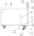
List of reference numerals: 1. a support beam; 11. a rack; 2. a base plate; 21. a traveling wheel; 22. a drive motor; 23. a gear; 3. a first guard plate; 31. a first folding plate; 32. a second folding plate; 33. automatically telescoping the rod; 4. a second guard plate; 5. a third guard plate; 6. a baffle plate; 7. a mounting ring; 8. a pin rod.
Detailed Description
The technical solutions in the embodiments of the present invention will be described clearly and completely with reference to the accompanying drawings in the embodiments of the present invention, and it is obvious that the described embodiments are only some embodiments of the present invention, not all embodiments. Based on the embodiments in the present invention, all other embodiments obtained by a person skilled in the art without creative work belong to the protection scope of the present invention.
It should be noted that in the description of the present invention, the terms "center", "upper", "lower", "left", "right", "vertical", "horizontal", "inner", "outer", etc. indicating the directions or positional relationships are based on the directions or positional relationships shown in the drawings, which are only for convenience of description, and do not indicate or imply that the device or element must have a specific orientation, be constructed and operated in a specific orientation, and thus, should not be construed as limiting the present invention. Furthermore, the terms "first," "second," and "third" are used for descriptive purposes only and are not to be construed as indicating or implying relative importance.
The utility model relates to a construction is with concrete embodiment of platform of unloading: as shown in fig. 1 to 3 and with reference to the orientation shown in fig. 2, the unloading platform for building construction comprises two support beams 1 and a bottom plate 2 connected with the two support beams 1, wherein the two support beams 1 are connected with a main structure in a floor plate through U-shaped steel bar anchor rings. The upper surface of the bottom plate 2 is connected with a first guard plate 3, a second guard plate 4 and a third guard plate 5, wherein the first guard plate 3 and the third guard plate 5 are oppositely arranged left and right and are parallel to the supporting beam 1, the second guard plate 4 is perpendicular to and connected with the first guard plate 3 and the third guard plate 5, the top of the first guard plate 3 is fixedly connected with a first folding plate 31, the left side of the first folding plate 31 is provided with a second folding plate 32, the second folding plate 32 is hinged with the top of the first folding plate 31, automatic telescopic rods 33 are respectively arranged between the front ends and the rear ends of the first folding plate 31 and the second folding plate 32, one end of each automatic telescopic rod 33 is hinged with a position of the first folding plate 31 close to the bottom, and the other end of each automatic telescopic rod is hinged with a position of the second folding plate 32 close to the middle; a baffle 6 is arranged between the first guard plate 3 and the third guard plate 5, and the baffle 6 is parallel to the first guard plate 3 and is detachably connected with the bottom plate 2.
When a constructor receives materials or feeds materials, the automatic telescopic rod 33 is controlled to extend to drive the second folding plate 32 to rotate upwards and unfold, and the second folding plate 32 forms protection at the top of the constructor, so that the head of the constructor is prevented from being damaged by the materials; through setting up baffle 6, baffle 6 is divided into two with the space of the platform of unloading, provides the space of standing for constructor can stand and connect material or pay-off in the space that baffle 6 and first backplate 3 formed, avoids the material to cause collision or fish tail to constructor's health, improves the security of the platform use of unloading.
Wherein, the vertical cross-section of baffle 6 is the style of calligraphy of falling T, has seted up the spout that vertical cross-section is the C type on the bottom plate 2, and the spout extends along a supporting beam 1's length direction, and baffle 6 passes through spout and 2 sliding connection of bottom plate. With baffle 6 and bottom plate 2 sliding connection, guarantee the stable connection of baffle 6 and bottom plate 2 on the one hand, form substantive protection to constructor, on the other hand, when carrying the material on the platform of unloading to the floor in, can dismantle baffle 6 along the spout roll-off on bottom plate 2, provide space for carrying the material, convenient operation.
With continued reference to fig. 1 and 2, the supporting beam 1 is an i-beam, the bottom of the bottom plate 2 is provided with a walking wheel 21, the walking wheel 21 spans two sides of a web plate of the i-beam and contacts with a bottom wing plate of the i-beam, and the tail end of the supporting beam 1 is provided with a stop block to prevent the walking wheel 21 from slipping off the supporting beam 1; the bottom of the bottom plate 2 is provided with a driving motor 22 at a position far away from the floor plate, the output end of the driving motor 22 is provided with a gear 23, the bottom of the support beam 1 is provided with a rack 11 along the length direction, and the gear 23 is meshed with the rack 11. The driving motor 22 drives the gear 23 to rotate along the rack 11, so as to drive the bottom plate 2 to move along the supporting beam 1, so that the unloading platform can be moved to a floor, and a constructor can carry materials on the unloading platform to the floor conveniently.
Continuing to refer to fig. 1 and 2, the third guard plate 5 is hinged to the bottom plate 2, one side, close to each other, of the third guard plate 5 and one side, close to each other, of the second guard plate 4, are respectively provided with mounting rings 7 which are distributed at intervals in the vertical direction, the mounting rings 7 of the third guard plate 5 and the second guard plate 4 are distributed in the vertical direction in a crossed mode, the discharging platform for building construction further comprises a pin rod 8, the top of the pin rod 8 extends in the circumferential direction to form a convex edge, the maximum diameter of the top of the pin rod 8 is larger than the inner diameter of the mounting ring 7, and the pin rod 8 penetrates through the mounting rings 7 to connect the third guard plate 5 and the second guard plate 4.
Drive gear 23 at driving motor 22 and rotate along rack 11, drive bottom plate 2 along a supporting beam 1 activity to gear 23 when being close to the floor board, first backplate 3, second backplate 4, the platform of unloading that third backplate 5 and bottom plate 2 formed is located the floor, extract pin 8, third backplate 5 rotates downwards and expandes, conveniently unload the uninstallation and the loading of material on the platform, insert or extract the collar 7 through pin 8 and realize the connection or the split of second backplate 4 and third backplate 5, the operation is simple and fast.
The utility model discloses a construction is with platform of unloading's specific use as follows: when the tower crane lifts materials to the position above the unloading platform, the baffle 6 slides into the chute to be stably connected with the bottom plate 2, the automatic telescopic rod 33 is controlled to extend, the second folding plate 32 rotates upwards to be unfolded, and protection is formed at the top of a constructor; after the material is placed on the bottom plate 2 and the tower crane hook is separated, the automatic telescopic rod 33 is controlled to be shortened, and the second folding plate 32 is folded back towards the first folding plate 31; controlling a driving motor 22 to drive a gear 23 to rotate along a rack 11 to drive a bottom plate 2 to move into a floor along a support beam 1; the baffle 6 slides out along the sliding groove on the bottom plate 2, the pin rod 8 at the joint of the second protection plate 4 and the third protection plate 5 is pulled out, and the third protection plate 5 rotates downwards and is unfolded onto the floor plate, so that the materials are conveniently conveyed and unloaded; after the unloading of the materials is finished, the third guard plate 5 is rotated upwards until the mounting ring 7 of the third guard plate is vertically aligned with the mounting ring 7 on the second guard plate 4 in a crossed manner, so that the pin rod 8 is inserted into the mounting ring 7, and the connection of the third guard plate 5 and the second guard plate 4 is finished; the driving motor 22 is controlled to drive the gear 23 to rotate along the rack 11, so as to drive the bottom plate 2 to move along the support beam 1 until the front end of the bottom plate 2 is flush with the edge of the floor plate.
In the above-mentioned embodiment, the vertical cross-section of baffle is the style of calligraphy of falling T, has seted up the spout that vertical cross-section is the C type on the bottom plate, and the baffle passes through spout and bottom plate sliding connection, and in other embodiments, the baffle still can set up to outside extension in both sides has the dog, has seted up the through-hole on the dog, set up on the bottom plate with the mounting hole of through-hole adaptation, the screw runs through the through-hole and is connected with the mounting hole, realizes being connected dismantling of baffle and bottom plate.
In the above embodiments, the automatic telescopic rods are respectively disposed between the front ends and the rear ends of the first folding plate and the second folding plate, and in other embodiments, the automatic telescopic rods may be further disposed at the front ends or the rear ends of the first folding plate and the second folding plate.
The above description is only a preferred embodiment of the present invention, and should not be taken as limiting the invention, and any modifications, equivalent replacements, improvements, etc. made within the spirit and principle of the present invention should be included in the protection scope of the present invention.
Claims (4)
1. The discharging platform for building construction is characterized by comprising two supporting beams and a bottom plate connected with the two supporting beams, wherein a first protection plate, a second protection plate and a third protection plate are connected to the upper surface of the bottom plate, the first protection plate and the third protection plate are oppositely arranged and are parallel to the supporting beams, the second protection plate is perpendicular to and connected with the first protection plate and the third protection plate, a first folding plate is fixedly connected to the top of the first protection plate, a second folding plate is arranged on one side, close to the third protection plate, of the first folding plate, the second folding plate is hinged to the top of the first folding plate, an automatic telescopic rod is arranged between the first folding plate and the second folding plate, and two ends of the automatic telescopic rod are respectively hinged to the first folding plate and the second folding plate; a baffle is arranged between the first guard plate and the third guard plate, and the baffle is parallel to the first guard plate and is detachably connected with the bottom plate.
2. The discharging platform for building construction according to claim 1, wherein the vertical section of the baffle is in an inverted T shape, the bottom plate is provided with a chute with a C-shaped vertical section, the chute extends along the length direction of the supporting beam, and the baffle is slidably connected with the bottom plate through the chute.
3. The discharging platform for building construction according to claim 1 or 2, wherein the supporting beam is an I-shaped steel, a traveling wheel is arranged at the bottom of the bottom plate, the traveling wheel is arranged on two sides of a web plate of the I-shaped steel in a spanning mode and is in contact with a bottom wing plate of the I-shaped steel, a stop block is arranged at the tail end of the supporting beam, a driving motor is arranged at the bottom of the bottom plate, a gear is arranged at the output end of the driving motor, a rack is arranged at the bottom of the supporting beam along the length direction of the supporting beam, and the gear is meshed with the rack.
4. The discharging platform for building construction according to claim 3, wherein the third guard plate is hinged to the bottom plate, mounting rings are arranged on one side, close to each other, of the third guard plate and one side, close to the second guard plate, of the second guard plate, the mounting rings are arranged at intervals in the vertical direction, the mounting rings of the third guard plate and the mounting rings of the second guard plate are distributed in a vertically crossed mode, the discharging platform for building construction further comprises a pin rod, a convex edge extends from the top of the pin rod in the circumferential direction, the maximum diameter of the top of the pin rod is larger than the inner diameter of the mounting rings, and the pin rod penetrates through the mounting rings to connect the third guard plate and the second guard plate.
Priority Applications (1)
| Application Number | Priority Date | Filing Date | Title |
|---|---|---|---|
| CN202120799569.4U CN214696962U (en) | 2021-04-19 | 2021-04-19 | Construction is with platform of unloading |
Applications Claiming Priority (1)
| Application Number | Priority Date | Filing Date | Title |
|---|---|---|---|
| CN202120799569.4U CN214696962U (en) | 2021-04-19 | 2021-04-19 | Construction is with platform of unloading |
Publications (1)
| Publication Number | Publication Date |
|---|---|
| CN214696962U true CN214696962U (en) | 2021-11-12 |
Family
ID=78532126
Family Applications (1)
| Application Number | Title | Priority Date | Filing Date |
|---|---|---|---|
| CN202120799569.4U Active CN214696962U (en) | 2021-04-19 | 2021-04-19 | Construction is with platform of unloading |
Country Status (1)
| Country | Link |
|---|---|
| CN (1) | CN214696962U (en) |
-
2021
- 2021-04-19 CN CN202120799569.4U patent/CN214696962U/en active Active
Similar Documents
| Publication | Publication Date | Title |
|---|---|---|
| CN105236276A (en) | Foldable gantry crane capable of ascending and descending | |
| US4134237A (en) | Modular section mast | |
| CA1207120A (en) | Portable asphalt storage silo | |
| CN214696962U (en) | Construction is with platform of unloading | |
| JP5028026B2 (en) | Mobile crane lattice boom | |
| CN207793892U (en) | A kind of T beams suspension operation platform structure | |
| CN213774378U (en) | Assembled building safety construction platform | |
| CA2270331C (en) | Scaffold conveyor system | |
| CN114232968A (en) | Attached lifting scaffold device | |
| CN217147010U (en) | Multilayer reinforcing bar strorage device | |
| CN212453691U (en) | Construction is with platform of unloading | |
| CN219469398U (en) | Bridging type lifting platform | |
| CN218091947U (en) | Suspension type hanging basket | |
| CN220745145U (en) | Girder steel transfer device | |
| CN217051531U (en) | Convenient-to-discharge material lifting bucket | |
| JPH042130B2 (en) | ||
| CN215558720U (en) | Automatic loading and unloading assembly for numerical control production line of green building prefabricated parts | |
| CN210767898U (en) | Building engineering platform of unloading | |
| CN215212257U (en) | A flexible foldable steel platform for elevartor shaft | |
| CN214326572U (en) | Slope device and plate trailer with slope device | |
| CN219708901U (en) | Transport hanging table of shore bridge and shore bridge | |
| CN213202175U (en) | Connecting suspension arm for tower crane | |
| CN114105023B (en) | Building materials is removal with removing lift freight train | |
| CN212076143U (en) | Nested cage of convenient transportation building block | |
| JPH0325398B2 (en) |
Legal Events
| Date | Code | Title | Description |
|---|---|---|---|
| GR01 | Patent grant | ||
| GR01 | Patent grant |