CN214605050U - Mould conveying device - Google Patents
Mould conveying device Download PDFInfo
- Publication number
- CN214605050U CN214605050U CN202120189784.2U CN202120189784U CN214605050U CN 214605050 U CN214605050 U CN 214605050U CN 202120189784 U CN202120189784 U CN 202120189784U CN 214605050 U CN214605050 U CN 214605050U
- Authority
- CN
- China
- Prior art keywords
- plate
- loading board
- centre gripping
- electric cylinder
- driving
- Prior art date
- Legal status (The legal status is an assumption and is not a legal conclusion. Google has not performed a legal analysis and makes no representation as to the accuracy of the status listed.)
- Active
Links
Images


Landscapes
- On-Site Construction Work That Accompanies The Preparation And Application Of Concrete (AREA)
Abstract
The utility model belongs to the technical field of recycled concrete generates equipment and specifically relates to a mould conveyor is related to, and it includes the driving, be provided with two couples on the driving, two be provided with the fixed subassembly of centre gripping that is used for pressing from both sides to get fixed mould on the couple, the fixed subassembly of centre gripping hangs the loading board of establishing including supplying the couple, be provided with a plurality of holders and mounting on the loading board. This application has the effect that improves concrete mold conveying efficiency.
Description
Technical Field
The application relates to the field of recycled concrete generating equipment, in particular to a mold conveying device.
Background
To produce concrete structures, recycled aggregate slurry is often poured into concrete molds for setting. In the production process, the concrete mould is often required to be moved and transported due to site modification or introduction of a new concrete mould.
In the related art, a travelling crane is often used for transporting the concrete mould, and then an operator binds the concrete mould through a steel wire rope and then hangs the concrete mould on a clamp of the travelling crane, so that the concrete mould is fixed, and then the travelling crane drives the concrete mould to move.
Aiming at the related technologies, the inventor finds that the concrete mould is bound manually through the steel wire, the binding time is long, and the defect that the overall transportation efficiency of the concrete mould is low is caused.
SUMMERY OF THE UTILITY MODEL
In order to improve concrete mold's whole conveying efficiency, this application provides a mould conveyor.
The application provides a mould conveyor adopts following technical scheme:
the utility model provides a mould conveyor, includes the driving, be provided with two couples on the driving, two be provided with the fixed subassembly of centre gripping that is used for pressing from both sides to get fixed mould on the couple, the fixed subassembly of centre gripping is including supplying the couple to hang the loading board of establishing, be provided with a plurality of holders and mounting on the loading board.
Through adopting above-mentioned technical scheme, move down through the driving drive loading board, then through the holder with the automatic centre gripping back of concrete mould, fix a position concrete mould axial through the mounting to reach the effect that automatic clamp was got and is fixed concrete mould, thereby reduce concrete mould fixed time, thereby improve concrete mould conveying efficiency.
Optionally, a plurality of the clamping pieces are arranged at equal intervals along the length direction of the bearing plate.
Through adopting above-mentioned technical scheme, guarantee that concrete mold receives even clamping-force along self length direction to guarantee the stability of concrete removal in-process.
Optionally, the clamping part comprises a rotating table arranged on the bearing plate, the rotating table is provided with two clamping jaws in a rotating mode, and a clamping driving part for driving the two clamping jaws to clamp is arranged on the bearing plate.
By adopting the technical scheme, the clamping jaws are only required to be driven to fold through the clamping driving piece, so that the effect of automatically clamping the concrete mould is achieved.
Optionally, the clamping driving piece comprises a vertical downward clamping electric cylinder arranged on the bearing plate, a driving platform is connected onto a telescopic rod on the clamping electric cylinder, two driving connecting rods are hinged onto the driving platform, and the two driving connecting rods are hinged to the two clamping jaws in a one-to-one correspondence manner.
Through adopting above-mentioned technical scheme, drive the drive table through elevator motor and be close to and rotate the platform to make two drive connecting rods and the distance between the clamping jaw tie point crescent, make two clamping jaws keep away from drive connecting rod one end and be close to each other, thereby play the effect of automatic centre gripping concrete mold.
Optionally, the fixing part comprises a fixed plate fixed at one end of the bearing plate in the length direction, a movable slide rail arranged along the length direction of the bearing plate is arranged on the bearing plate, a sliding plate is arranged on the movable slide rail in a sliding manner, a pressing driving part for driving the sliding plate to slide along the movable slide rail is arranged on the bearing plate, and a movable plate for pressing the concrete mold is arranged on the sliding plate.
Through adopting above-mentioned technical scheme, drive the shifting plank through compressing tightly the driving piece and remove to the movable plate that drives on the shifting plank is close to and decides the board, thereby makes concrete mold axial compressed tightly fixedly.
Optionally, a vertical downward lifting electric cylinder is arranged on the sliding plate, a telescopic rod of the lifting electric cylinder is connected with the movable plate, and a through groove for the movable plate to penetrate through is arranged on the bearing plate.
Through adopting above-mentioned technical scheme, drive the movable plate through the electric jar that goes up and down, withdrawal loading board top to be convenient for press from both sides and get the concrete form under the different topography circumstances.
Optionally, a through groove for the movable plate to pass through is formed in each bearing plate between every two adjacent clamping pieces.
Through adopting above-mentioned technical scheme for the movable plate can follow the slide plate and remove to two arbitrary holder one sides, thereby change the distance between movable plate and the roof and in order to satisfy the fixed demand of concrete mold of different length.
Optionally, the movable plate includes a vertical abutting portion connected to the telescopic rod of the electric lift cylinder, and a horizontal supporting portion disposed at an end of the abutting portion away from the electric lift cylinder.
Through adopting above-mentioned technical scheme for put on the supporting part when concrete mold butt on butt portion, thereby guarantee concrete mold's stability.
In summary, the present application includes at least one of the following beneficial technical effects:
1. the concrete mould is automatically clamped by the clamping piece, and then the concrete mould is tightly pressed by the fixing piece, so that the concrete mould is not required to be manually fixed, and the improvement is achieved;
2. the lifting electric cylinder and the through groove are arranged, so that the movable plate can be positioned on the side edge of any clamping piece, and the fixing requirements of concrete moulds with different lengths are met.
Drawings
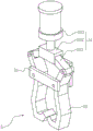
Fig. 1 is a schematic overall structure diagram of a mold conveying device according to an embodiment of the present application.
Fig. 2 is a schematic structural diagram of a clamping and fixing assembly in a mold conveying device according to an embodiment of the present application.
Fig. 3 is a schematic structural diagram of a clamping member in a mold conveying device according to an embodiment of the present application.
Description of reference numerals: 1. driving a vehicle; 2. hooking; 3. a carrier plate; 4. hanging a ring; 5. a clamping member; 51. a rotating table; 52. a clamping jaw; 53. clamping the driving member; 531. clamping an electric cylinder; 532. a drive stage; 533. a drive link; 6. a fixing member; 61. fixing a plate; 62. moving the slide rail; 63. a slide plate; 64. compressing the driving member; 65. a support frame; 66. a lifting electric cylinder; 67. a movable plate; 671. an abutting portion; 672. a bearing part; 68. and (6) penetrating through the groove.
Detailed Description
The present application is described in further detail below with reference to figures 1-3.
The embodiment of the application discloses a mould conveying device. Referring to fig. 1 and 2, the mold conveying apparatus includes a traveling crane 1. The travelling crane 1 is provided with two hooks 2 for hooking and holding goods. The two hooks 2 are hung with clamping and fixing components for clamping and fixing the concrete mould. The fixed subassembly of centre gripping includes loading board 3, and loading board 3 is fixed with link 4 along the equal both ends that support length direction, and two couples 2 are hung respectively and are established on two link 4. The bearing plate 3 is provided with a fixing piece 6 for clamping the concrete mould and a plurality of clamping pieces 5.
Referring to fig. 2 and 3, a plurality of clamping members 5 are provided at equal intervals along the length direction of the loading plate 3. The clamping piece 5 comprises a rotating table 51 fixed on the bottom wall of the bearing plate 3, two clamping jaws 52 are arranged on the rotating table 51, two rotating shafts are arranged on the rotating table 51, a rotating groove for the rotating shaft to penetrate is formed in each clamping jaw 52, and the clamping jaws 52 are arranged on the rotating shafts in a penetrating mode. The carrier plate 3 is provided with a clamp driving member 53 for driving the two clamping jaws 52 to rotate. The clamping driving member 53 comprises a clamping electric cylinder 531 fixed on the bearing plate 3 and arranged downwards, a driving table 532 is fixed on an expansion link of the clamping electric cylinder 531, two driving connecting rods 533 are connected to the driving table 532 through pin shafts, and one end, far away from the driving table 532, of each driving connecting rod 533 is connected with one clamping jaw 52 through a pin shaft. The driving table 532 is driven by the lifting motor to be close to the rotating table 51, so that the distance between the connection points of the two driving connecting rods 533 and the clamping jaws 52 is gradually increased, one ends of the two clamping jaws 52 far away from the driving connecting rods 533 are close to each other, and a clamping effect is achieved; and vice versa to release the two jaws 52.
Referring to fig. 2 and 3, the fixing member 6 includes a top plate fixed to one side of the loading plate 3 in the length direction, and the fixed plate 61 has an L-shaped longitudinal section, so that one end of the concrete form in the length direction abuts against a vertical sidewall of the fixed plate 61, and the concrete form is fixed to a horizontal bottom wall of the fixed plate 61. A pair of movable sliding rails 62 is further fixed on the top wall of the bearing plate 3, and the movable sliding rails 62 are arranged along the length direction of the bearing plate 3. Be provided with the shifting board 63 on the sliding rail 62, be provided with the drive shifting board 63 on the loading board 3 and follow the gliding driving piece 64 that compresses tightly of shifting rail 62, compress tightly driving piece 64 and be the servo motor who fixes on loading board 3, servo motor's axis of rotation passes through ball screw mechanism and is connected with the transmission of shifting board 63 to make servo motor drive shifting board 63 move along shifting rail 62. A support frame 65 is fixed on the upper bottom wall of the sliding plate 63, a vertically downward lifting electric cylinder 66 is fixed on the support frame 65, and a movable plate 67 is fixedly connected to the telescopic rod of the lifting electric cylinder 66. The sliding plate 63 is provided with a through groove for the movable plate 67 to pass through, so that the movable plate 67 can be retracted above the sliding plate 63. The carrying plate 3 is formed with a plurality of through-grooves 68 through which the moving plate 67 passes, so that the moving plate 67 can pass through the through-grooves 68 to extend below the carrying plate 3. All be provided with through groove 68 on the loading board 3 between per two adjacent holder 5 for movable plate 67 can follow slide plate 63 and move to arbitrary two holder 5 one side, thereby changes the distance between movable plate 67 and the roof and in order to satisfy the fixed demand of concrete mold of different length. Compress tightly driving piece 64 and drive slide plate 63 and slide along removing slide rail 62 to make movable plate 67 on the slide plate 63 follow slide plate 63 and remove, thereby make movable plate 67 be close to or keep away from movable plate 67, thereby reach and compress tightly concrete mold both ends, reduce the effect that concrete mold motion in-process removed, guarantee the stability that concrete mold removed.
The movable plate 67 includes an abutting portion 671 fixed to the extension rod of the electric lift cylinder 66, and the abutting portion 671 is vertically disposed. One end of the abutting part 671, which is far away from the lifting electric cylinder 66, is fixed with a horizontal bearing part 672, so that the concrete mold is abutted on the abutting part 671 and simultaneously placed on the bearing part 672, and the stability of the concrete mold is ensured.
The implementation principle of the mold conveying device in the embodiment of the application is as follows: drive loading board 3 through driving a vehicle 1 and move down, then drive clamping jaw 52 centre gripping through centre gripping electric cylinder 531 to make the concrete mould by the centre gripping, then drive movable plate 67 through compressing tightly driving piece 64 and remove to deciding board 61, thereby make the concrete mould compressed tightly among movable plate 67 and deciding board 61, thereby the centre gripping of accomplishing the concrete is fixed, then drive the concrete mould removal on the loading board 3 through driving a vehicle 1.
The above embodiments are preferred embodiments of the present application, and the protection scope of the present application is not limited by the above embodiments, so: all equivalent changes made according to the structure, shape and principle of the present application shall be covered by the protection scope of the present application.
Claims (8)
1. A mold conveying device is characterized in that: including driving (1), be provided with two couples (2) on driving (1), two be provided with the fixed subassembly of centre gripping that is used for pressing from both sides to get fixed mould on couple (2), the fixed subassembly of centre gripping hangs loading board (3) of establishing including supplying couple (2), be provided with a plurality of holders (5) and mounting (6) on loading board (3).
2. A mold transfer apparatus as set forth in claim 1, wherein: a plurality of the clamping pieces (5) are arranged at equal intervals along the length direction of the bearing plate (3).
3. A mold transfer apparatus as set forth in claim 1, wherein: holder (5) are including setting up rotation platform (51) on loading board (3), it is provided with two clamping jaws (52) to rotate on rotation platform (51), be provided with centre gripping driving piece (53) of two clamping jaw (52) centre grippings of drive on loading board (3).
4. A mold transfer apparatus according to claim 3, wherein: centre gripping driving piece (53) are including setting up vertical decurrent centre gripping electric cylinder (531) on loading board (3), be connected with drive platform (532) on the telescopic link on centre gripping electric cylinder (531), it has two drive connecting rod (533) to articulate on drive platform (532), two drive connecting rod (533) are articulated with two clamping jaw (52) one-to-one.
5. A mold transfer apparatus as set forth in claim 1, wherein: mounting (6) are including fixing fixed plate (61) in loading board (3) length direction one end, be provided with on loading board (3) along the movable slide rail (62) that loading board (3) length direction set up, it is provided with slide plate (63) to slide on movable slide rail (62), be provided with drive slide plate (63) on loading board (3) and compress tightly driving piece (64) along movable slide rail (62) gliding, be provided with movable plate (67) that are used for compressing tightly the concrete mould on slide plate (63).
6. A mold transfer apparatus as set forth in claim 5, wherein: the sliding plate (63) is provided with a vertically downward lifting electric cylinder (66), an expansion rod of the lifting electric cylinder (66) is connected with the movable plate (67), and the bearing plate (3) is provided with a through groove (68) for the movable plate (67) to penetrate through.
7. A mold transfer apparatus as set forth in claim 6, wherein: and through grooves (68) for the movable plate (67) to pass through are formed in the bearing plates (3) between every two adjacent clamping pieces (5).
8. A mold transfer apparatus as set forth in claim 5, wherein: the movable plate (67) comprises a vertical abutting part (671) connected with the telescopic rod of the lifting electric cylinder (66) and a horizontal supporting part (672) arranged at one end of the abutting part (671) far away from the lifting electric cylinder (66).
Priority Applications (1)
| Application Number | Priority Date | Filing Date | Title |
|---|---|---|---|
| CN202120189784.2U CN214605050U (en) | 2021-01-23 | 2021-01-23 | Mould conveying device |
Applications Claiming Priority (1)
| Application Number | Priority Date | Filing Date | Title |
|---|---|---|---|
| CN202120189784.2U CN214605050U (en) | 2021-01-23 | 2021-01-23 | Mould conveying device |
Publications (1)
| Publication Number | Publication Date |
|---|---|
| CN214605050U true CN214605050U (en) | 2021-11-05 |
Family
ID=78438090
Family Applications (1)
| Application Number | Title | Priority Date | Filing Date |
|---|---|---|---|
| CN202120189784.2U Active CN214605050U (en) | 2021-01-23 | 2021-01-23 | Mould conveying device |
Country Status (1)
| Country | Link |
|---|---|
| CN (1) | CN214605050U (en) |
-
2021
- 2021-01-23 CN CN202120189784.2U patent/CN214605050U/en active Active
Similar Documents
| Publication | Publication Date | Title |
|---|---|---|
| CN108262604B (en) | Full-automatic screw disassembling machine | |
| CN210910008U (en) | Tray transplanting manipulator for sand core conveying line | |
| CN212126801U (en) | Brick unloading manipulator for sintering brick pile | |
| CN111872361B (en) | Multi-station steel ingot demolding system and method | |
| CN112479043A (en) | Heavy-load material loading and unloading manipulator | |
| CN111231090B (en) | Full-automatic efficient evaporates presses aerated concrete block shedder | |
| CN210996437U (en) | Sand casting production line | |
| CN210552069U (en) | Automatic change leak board production line | |
| CN214605050U (en) | Mould conveying device | |
| CN209635759U (en) | A kind of reinforcing bar cage hoisting machine | |
| CN111204674A (en) | Workpiece up-down transferring material lifter | |
| CN211225529U (en) | Novel brick plate pile lifting separation equipment | |
| CN211254460U (en) | Shifting chuck mechanism in brick making and stacking | |
| CN210285985U (en) | Traveling frame brick unloading and loading equipment | |
| CN209416016U (en) | A kind of dry kiln car automatic loader and unloader structure | |
| CN208147845U (en) | A kind of automatic material-fetching mechanical hand on ingot stripper | |
| CN216299649U (en) | Green brick marshalling and transfer device | |
| CN113023366B (en) | Wallboard discharging device and method | |
| CN220926044U (en) | Tongs convenient to box transport | |
| CN216329032U (en) | Ferry conveying device and side die conveying and cleaning system | |
| CN217317983U (en) | Rotor taking and transplanting manipulator | |
| CN216638698U (en) | Lifting equipment for machining materials | |
| CN217229376U (en) | Aerated brick clamping device | |
| CN213265435U (en) | Building block hoisting device | |
| CN219296512U (en) | Silicon rod turn-over device |
Legal Events
| Date | Code | Title | Description |
|---|---|---|---|
| GR01 | Patent grant | ||
| GR01 | Patent grant |