CN214564625U - Transmission suspension - Google Patents
Transmission suspension Download PDFInfo
- Publication number
- CN214564625U CN214564625U CN202120007507.5U CN202120007507U CN214564625U CN 214564625 U CN214564625 U CN 214564625U CN 202120007507 U CN202120007507 U CN 202120007507U CN 214564625 U CN214564625 U CN 214564625U
- Authority
- CN
- China
- Prior art keywords
- main spring
- lower support
- plate
- transmission suspension
- upper support
- Prior art date
- Legal status (The legal status is an assumption and is not a legal conclusion. Google has not performed a legal analysis and makes no representation as to the accuracy of the status listed.)
- Active
Links
Images


Landscapes
- Vibration Prevention Devices (AREA)
Abstract
The utility model relates to a derailleur suspension, it includes upper bracket, lower carriage to and press from both sides and establish the main spring rubber that links firmly between upper bracket and lower carriage, and be equipped with connecting portion on the upper bracket, be equipped with down connecting portion on the lower carriage, main spring rubber is two of symmetrical arrangement, and is equipped with rigid partition portion in each main spring rubber, and each main spring rubber has the upper portion colloid that links firmly with the upper bracket because of the partition of partition portion, and the lower part colloid that links firmly with the lower carriage. Derailleur suspension, through set up rigid partition portion in main spring rubber, can effectively improve the quiet rigidity of this suspension, and less to the increase of dynamic stiffness to can make this suspension have lower sound than, and then can promote the NVH performance of whole car.
Description
Technical Field
The utility model relates to a vehicle parts technical field, in particular to derailleur suspension.
Background
The transmission suspension is generally adopted for vibration reduction and noise reduction on a vehicle, and the existing transmission suspension generally comprises a suspension upper plate, a suspension lower plate and a limiting bolt. The suspension upper plate and the suspension lower plate are vulcanized together through rubber, and then the limit bolt is assembled for limiting, so that the transmission of the vibration of the engine can be isolated, and the displacement of the power assembly is limited. However, due to the unreasonable structural design, the existing transmission suspension has higher static stiffness but higher dynamic stiffness, so that the comfort of the whole vehicle is reduced.
SUMMERY OF THE UTILITY MODEL
In view of this, the utility model aims at providing a derailleur suspension, it can have higher static rigidity and lower sound to static ratio, can improve the NVH performance of whole car.
In order to achieve the above purpose, the technical scheme of the utility model is realized like this:
a transmission suspension comprises an upper support, a lower support and main spring rubbers clamped and fixedly connected between the upper support and the lower support, wherein an upper connecting part is arranged on the upper support, a lower connecting part is arranged on the lower support, the main spring rubbers are symmetrically arranged, a rigid separating part is arranged in each main spring rubber, and each main spring rubber is provided with an upper colloid fixedly connected with the upper support and a lower colloid fixedly connected with the lower support due to the separation of the separating parts.
Further, the partition part adopts a partition plate.
Further, the partition plate is made of a steel plate.
Furthermore, the upper bracket is provided with a pair of upper support plates which are arranged in an upturned manner and a pair of lower support plates which are arranged in a downturned manner, the upper connection part is arranged on each upper support plate, and the two main spring rubbers are arranged on the two lower support plates in a one-to-one correspondence manner.
Furthermore, a connecting line between the two upper supporting plates is orthogonal to a connecting line between the two lower supporting plates.
Furthermore, the upper connecting part is a connecting hole arranged on each upper supporting plate.
Furthermore, the lower support comprises a bottom plate and a connecting plate fixedly connected to the bottom plate, the connecting plate is bent and provided with two connecting sections which are parallel or approximately parallel to the lower support plates in a one-to-one correspondence manner, the two main spring rubbers are arranged at the two connecting sections in a one-to-one correspondence manner, and the lower connecting sections are arranged on the bottom plate.
Furthermore, the lower connecting part is a connecting bolt arranged on the bottom plate.
Furthermore, a limiting bolt located between the two main spring rubbers is connected between the upper support and the lower support, the limiting bolt penetrates through the upper support through the limiting rubber, a limiting nut located at the lower support is connected to the limiting bolt in a threaded manner, and the limiting nut can be abutted to the lower support along with the stretching of the two main spring rubbers.
Furthermore, guard plates which are correspondingly shielded below the main spring rubbers are arranged on the lower support, and the guard plates are made of rubber.
Compared with the prior art, the utility model discloses following advantage has:
derailleur suspension, through set up rigid partition portion in main spring rubber, can effectively improve the quiet rigidity of this suspension, and less to the increase of dynamic stiffness to can make this suspension have lower sound than, and then can promote the NVH performance of whole car.
In addition, the partition part adopts the partition plate, so that the structure is simple, and the design and implementation are convenient. The upper bracket is composed of a pair of upper support plates arranged in an upturned mode and a pair of lower support plates arranged in a downward-turned mode, so that the upper bracket has good structural strength, and the transmission suspension has good static rigidity. And the upper connecting part adopts a connecting hole, so that the structure is simple, and the design and implementation are convenient.
In addition, the connecting plate is bent, so that the connection between the two main spring rubbers and the lower bracket can be facilitated. And the lower connecting part adopts a connecting bolt, so that the connection between the transmission suspension and an external part is facilitated. Through setting up spacing rubber, can further improve the damping performance of derailleur suspension. The guard plate which shields the lower part of the main spring rubber is arranged on the lower support, so that sundries splashed on the road surface can be effectively isolated, the main spring rubber can be prevented from being corroded, and the service life of the main spring rubber can be prolonged.
Drawings
The accompanying drawings, which form a part hereof, are included to provide a further understanding of the invention, and are incorporated in and constitute a part of this specification, illustrate embodiments of the invention and together with the description serve to explain the invention without undue limitation. In the drawings:
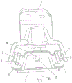
fig. 1 is a schematic structural diagram of a transmission mount according to an embodiment of the present invention;
fig. 2 is a schematic structural diagram of a transmission mount according to an embodiment of the present invention at another view angle;
FIG. 3 is a top view of FIG. 2;
fig. 4 is a schematic structural view of an upper bracket according to an embodiment of the present invention;
fig. 5 is a schematic structural view of a lower bracket according to an embodiment of the present invention;
fig. 6 is a schematic structural diagram of the main spring rubber and the guard plate according to an embodiment of the present invention.
Description of reference numerals:
1. an upper bracket; 101. an upper support plate; 102. a lower support plate; 103. connecting holes; 104. a through hole;
2. main spring rubber; 3. a partition plate; 4. a guard plate; 5. a limit bolt; 6. a connecting bolt;
7. a lower bracket; 701. a base plate; 702. a connecting plate; 703. mounting holes;
8. a limit nut; 9. limiting rubber; 10. an upper connector; 11. a lower connector.
Detailed Description
It should be noted that, in the present invention, the embodiments and features of the embodiments may be combined with each other without conflict.
In the description of the present invention, it should be noted that, if terms indicating orientation or positional relationship such as "upper", "lower", "inner", "outer", etc. appear, they are based on the orientation or positional relationship shown in the drawings, and are only for convenience of description and simplification of description, but do not indicate or imply that the device or element referred to must have a specific orientation, be constructed in a specific orientation, and be operated, and thus, should not be construed as limiting the present invention. Furthermore, the appearances of the terms first, second, etc. in this specification are not necessarily all referring to the same item, but are instead intended to cover the same item.
In addition, in the description of the present invention, the terms "mounted," "connected," and "connecting" are to be construed broadly unless otherwise specifically limited. For example, the connection can be fixed, detachable or integrated; can be mechanically or electrically connected; they may be connected directly or indirectly through intervening media, or they may be interconnected between two elements. To those of ordinary skill in the art, the specific meaning of the above terms in the present invention can be understood in combination with the specific situation.
The present invention will be described in detail below with reference to the accompanying drawings in conjunction with embodiments.
The present embodiment relates to a transmission mount, as shown in fig. 1 to 3, which includes an upper bracket 1, a lower bracket 7, and a main spring rubber 2 sandwiched and fixed between the upper bracket 1 and the lower bracket 7. As shown in fig. 4, in order to improve the structural strength of the upper bracket 1, the upper bracket 1 of the present embodiment has a pair of upper support plates 101 that are turned up, and a pair of lower support plates 102 that are turned down, and an upper connecting portion is provided on each of the upper support plates 101. And for the convenience of processing and manufacturing, the upper connecting part is specifically a connecting hole 103 formed on each upper support plate 101, and the connecting holes 103 on each upper support plate 101 are two arranged at intervals.
As shown in fig. 3, in order to obtain a better use effect, the connecting line between the two upper support plates 101 and the connecting line between the two lower support plates 102 of the present embodiment are arranged orthogonally. It should be noted that, in addition to the connection line between the two upper support plates 101 and the connection line between the two lower support plates 102 being orthogonally arranged, the included angle between the two connection lines may also be an acute angle. In addition, a through hole 104 is formed at the middle of the upper bracket 1 in order to facilitate the connection with the lower plate 102.
As shown in fig. 5 in combination with fig. 1 and 2, the lower frame 7 of this embodiment includes a bottom plate 701, and a connection plate 702 attached to the bottom plate 701, the connection plate 702 is protruded at a middle portion thereof so as to be bent, and the connection plate 702 has two connection segments arranged in parallel or nearly parallel with the lower plate 102 in a one-to-one correspondence. In addition, as shown in fig. 5, a mounting hole 703 is formed in the connection plate 702 corresponding to the through hole 104. Further, a lower connection portion, specifically, a connection bolt 6 provided on the bottom plate 701 is provided on the lower bracket 7 to be connected to the vehicle body.
As shown in fig. 1, the main spring rubbers 2 of the present embodiment are two and symmetrically arranged, the two main spring rubbers 2 are correspondingly clamped between the two lower support plates 102 and the two connecting sections, and each main spring rubber 2 is connected to the lower support plate 102 and the connecting section through vulcanization. In addition, in order to improve the static rigidity of the transmission suspension, rigid separating parts are arranged in the main spring rubbers 2, and each main spring rubber 2 is provided with an upper colloid fixedly connected with the upper bracket 1 and a lower colloid fixedly connected with the lower bracket 7 due to the separation of the separating parts.
As shown in fig. 1, the partition in the present embodiment specifically employs a partition plate 3 for ease of manufacturing. And as a possible embodiment, the partition plate 3 of the present embodiment is made of a steel plate. Of course, the partition plate 3 may be made of other rigid materials than steel plates, and the partition portion may be made of projections, ribs, or the like on the partition plate 3 instead of the flat partition plate 3.
In the present embodiment, in order to improve the vibration damping effect, as shown in fig. 6, a connecting body made of rubber is further connected between the two main spring rubbers 2. The connector comprises an upper connector 10 connected with two upper colloids respectively and a lower connector 11 connected with two lower colloids, and the upper connector 10 and the lower connector 11 are vulcanized and connected with an upper bracket 1 and a connecting plate 702 respectively. At this time, in order to further improve the use effect, the upper connecting body 10 is configured with the stopper rubber 9 embedded in the through hole 104, and the stopper rubber 9 is internally formed with a through hole through which the following stopper bolt 5 passes, and has a protrusion protruding toward the lower bracket 7 side.
It should be noted that, in the present embodiment, the two main spring rubbers 2 may be connected together by a connecting body, or may be provided separately without providing a connecting body, and in this case, the limiting rubber 9 may be separately embedded in the through hole 104.
Still as shown in fig. 1, a limiting bolt 5 located between the two main spring rubbers 2 is further connected between the upper bracket 1 and the lower bracket 7, the limiting bolt 5 is inserted into the through hole 104 and the mounting hole 703 through the limiting rubber 9, and a limiting nut 8 located at the bottom of the connecting plate 702 is screwed on the limiting bolt 5. And the limiting nut 8 can be abutted to the lower bracket 7 through the lower connecting body 11 along with the stretching of the two main spring rubbers 2, so that a better vibration isolation effect can be achieved. Wherein, the limit nut 8 only adopts the prior common nut.
In addition, in order to further improve the use effect, as shown in fig. 6 and fig. 1, the bottom plate 701 is provided with the protection plates 4 which are shielded under the main spring rubbers 2 in a one-to-one correspondence manner, and the protection plates 4 are made of rubber and are vulcanized with the main spring rubbers 2. Through setting up backplate 4, can effectively keep apart the debris that the road surface splashes to can prevent the corruption, and can improve the life-span of main spring rubber 2. In this embodiment, each guard plate 4 is turned up toward the main spring rubber 2 side in order to further improve the protection effect on the main spring rubber 2.
According to the transmission suspension, the partition plate 3 is arranged, so that the static rigidity of the suspension can be effectively improved, the increase of the dynamic rigidity is small, the suspension has a low dynamic-static ratio, and the NVH performance of the whole vehicle can be improved; in addition, set up backplate 4 and can play the guard action to main spring rubber 2, can prolong main spring rubber 2's life to can make this derailleur suspension have better practicality.
The above description is only a preferred embodiment of the present invention, and should not be taken as limiting the invention, and any modifications, equivalent replacements, improvements, etc. made within the spirit and principle of the present invention should be included in the protection scope of the present invention.
Claims (10)
1. A transmission suspension characterized by: the rubber spring comprises an upper support (1), a lower support (7) and main spring rubbers (2) which are clamped and fixedly connected between the upper support (1) and the lower support (7), wherein an upper connecting part is arranged on the upper support (1), a lower connecting part is arranged on the lower support (7), the main spring rubbers (2) are symmetrically arranged, rigid separating parts are arranged in the main spring rubbers (2), and each main spring rubber (2) is provided with an upper colloid fixedly connected with the upper support (1) and a lower colloid fixedly connected with the lower support (7) due to the separation of the separating parts.
2. The transmission suspension of claim 1, wherein: the partition part adopts a partition plate (3).
3. The transmission mount of claim 2 wherein: the partition plate (3) is made of a steel plate.
4. The transmission suspension of claim 1, wherein: the upper support (1) is provided with a pair of upper support plates (101) which are arranged in an upturned mode and a pair of lower support plates (102) which are arranged in a downturned mode, the upper connecting portion is arranged on each upper support plate (101), and the two main spring rubbers (2) are arranged on the two lower support plates (102) in a one-to-one correspondence mode.
5. The transmission suspension of claim 4, wherein: the connecting line between the two upper support plates (101) is orthogonal to the connecting line between the two lower support plates (102).
6. The transmission suspension of claim 4, wherein: the upper connecting parts are connecting holes (103) formed in the upper support plates (101).
7. The transmission suspension of claim 4, wherein: the lower support (7) comprises a bottom plate (701) and a connecting plate (702) fixedly connected to the bottom plate (701), the connecting plate (702) is bent and provided with two connecting sections which are parallel or approximately parallel to the lower support plates (102) in a one-to-one correspondence mode, the two main spring rubbers (2) are arranged at the two connecting sections in a one-to-one correspondence mode, and the lower connecting section is arranged on the bottom plate (701).
8. The transmission suspension of claim 7, wherein: the lower connecting part is a connecting bolt (6) arranged on the bottom plate (701).
9. The transmission suspension of claim 1, wherein: the upper support (1) and the lower support (7) are connected with a limiting bolt (5) between the two main spring rubbers (2), the limiting bolt (5) penetrates through the upper support (1) through a limiting rubber (9), a limiting nut (8) located at the lower support (7) is connected to the limiting bolt (5) in a threaded mode, the limiting nut (8) is stretched along with the two main spring rubbers (2), and the limiting nut (8) can be abutted to the lower support (7).
10. The transmission suspension of any one of claims 1-9, wherein: and the lower support (7) is provided with guard plates (4) which are correspondingly shielded below the main spring rubbers (2), and the guard plates (4) are made of rubber.
Priority Applications (1)
| Application Number | Priority Date | Filing Date | Title |
|---|---|---|---|
| CN202120007507.5U CN214564625U (en) | 2021-01-04 | 2021-01-04 | Transmission suspension |
Applications Claiming Priority (1)
| Application Number | Priority Date | Filing Date | Title |
|---|---|---|---|
| CN202120007507.5U CN214564625U (en) | 2021-01-04 | 2021-01-04 | Transmission suspension |
Publications (1)
| Publication Number | Publication Date |
|---|---|
| CN214564625U true CN214564625U (en) | 2021-11-02 |
Family
ID=78344158
Family Applications (1)
| Application Number | Title | Priority Date | Filing Date |
|---|---|---|---|
| CN202120007507.5U Active CN214564625U (en) | 2021-01-04 | 2021-01-04 | Transmission suspension |
Country Status (1)
| Country | Link |
|---|---|
| CN (1) | CN214564625U (en) |
-
2021
- 2021-01-04 CN CN202120007507.5U patent/CN214564625U/en active Active
Similar Documents
| Publication | Publication Date | Title |
|---|---|---|
| CN109131297B (en) | Electronic vacuum pump mounting rack and vehicle-mounted electronic vacuum pump | |
| CN214564625U (en) | Transmission suspension | |
| CN214092028U (en) | Water pump backing plate | |
| CN215334188U (en) | Top rubber assembly with strong shock resistance | |
| CN210734082U (en) | Steering wheel gasbag mounting structure, steering wheel and car | |
| CN202510603U (en) | Engine shock pad | |
| CN215705669U (en) | Suspension structure | |
| CN111946765A (en) | Power assembly suspension device and vehicle | |
| CN210363786U (en) | Vacuum pump installing support and vacuum pump | |
| JP4066682B2 (en) | Fuel tank support structure | |
| CN109139761B (en) | High-temperature-resistant high-resilience natural rubber resonance block | |
| CN212685702U (en) | Steering gear assembly and vehicle | |
| CN213501719U (en) | Suspension assembly wrapped by suspension spring and mounting disc assembly | |
| CN217898610U (en) | Conical rubber suspension | |
| CN216545713U (en) | Split type radiator suspension assembly and vehicle | |
| CN105216600B (en) | Suspension assembly for vehicle and vehicle with same | |
| CN217730161U (en) | Bearing structure and vehicle | |
| CN217778341U (en) | Automobile engine suspension support | |
| CN110284967B (en) | Multifunctional engine accessory mounting bracket assembly | |
| CN215826604U (en) | Get on bus movable pedal and car | |
| CN216231644U (en) | Multifunctional suspension support structure of electric automobile | |
| CN214205133U (en) | A mounting structure for wiper motor | |
| CN211901405U (en) | Bottom support structure for air conditioner and heat pump unit and shock pad thereof | |
| CN210129172U (en) | Server fan module with shock-absorbing function | |
| CN219263070U (en) | Decoupling assembly, decoupling device and vehicle |
Legal Events
| Date | Code | Title | Description |
|---|---|---|---|
| GR01 | Patent grant | ||
| GR01 | Patent grant |