CN214406693U - Equipment capable of refrigerating and heating simultaneously - Google Patents
Equipment capable of refrigerating and heating simultaneously Download PDFInfo
- Publication number
- CN214406693U CN214406693U CN202120344744.0U CN202120344744U CN214406693U CN 214406693 U CN214406693 U CN 214406693U CN 202120344744 U CN202120344744 U CN 202120344744U CN 214406693 U CN214406693 U CN 214406693U
- Authority
- CN
- China
- Prior art keywords
- cabinet body
- heating
- air
- partition plate
- partition board
- Prior art date
- Legal status (The legal status is an assumption and is not a legal conclusion. Google has not performed a legal analysis and makes no representation as to the accuracy of the status listed.)
- Active
Links
Images


Abstract
The utility model discloses a device capable of refrigerating and heating simultaneously, which comprises a cabinet body, a lamp box, an electric control chamber, an air deflector, a fan, a refrigerating unit and a heating device, wherein the lamp box is arranged at the top of the cabinet body; the left side and the right side in the cabinet body are provided with the partition plate brackets, and the back plate in the cabinet body is provided with the threading plate; the partition board support is internally provided with partition board layer frames at intervals, the middle part of the partition board layer frame is provided with a middle partition board layer frame, and an air return opening is arranged between the bottom of the partition board support and the air deflector at the bottom of the cabinet body. The equipment simultaneously comprises two functions of refrigeration and heating, and can be independently switched into refrigeration or heating respectively, so that a user can realize heating and cooling of articles by purchasing one equipment, the user cost is reduced, the user space is saved, and the requirements of different users are met.
Description
Technical Field
The utility model relates to a refrigeration heats technical field, concretely relates to equipment that can refrigerate simultaneously and heat.
Background
Most of air curtain cabinets, display cabinets and the like sold in the market at present are single refrigerating or single heating equipment, and the functions and the purposes are single. Only has a refrigerating function or only has a heating function, and how to realize cold and hot switching or the functions of refrigerating and heating simultaneously in the existing equipment is a technical problem to be solved, while in the existing equipment, when a user purchases one of the products, the user can only drink cold drinks in summer or hot drinks in winter, and the cold drinks and the hot drinks cannot be taken into consideration simultaneously; when two products are purchased, firstly, the occupied space is large; secondly, according to seasonal variation, the condition that one piece of equipment is idle can occur, and resources are wasted.
The invention relates to a device which can simultaneously refrigerate and heat and can switch full refrigeration and full heating, and can meet the requirements of people on cold drinks and hot drinks in any season or in the face of different people.
Disclosure of Invention
For solving the deficiencies existing in the prior art, the utility model provides a device capable of refrigerating and heating simultaneously.
The technical scheme of the utility model is that: the equipment capable of refrigerating and heating simultaneously comprises a cabinet body, a lamp box, an electric control chamber, an air deflector, a fan, a refrigerating unit and a heating device, wherein the lamp box is installed at the top of the cabinet body; the left side and the right side in the cabinet body are provided with the partition plate brackets, and the back plate in the cabinet body is provided with the threading plate; the partition board bracket is internally provided with partition board layer frames at intervals, the middle part of the partition board bracket is provided with a middle partition board layer frame, an air return opening is arranged between the bottom of the partition board bracket and the air deflector at the bottom of the cabinet body, and an air channel is arranged between the rear back board and the rear shell of the cabinet body.
Furthermore, the middle partition plate layer frame comprises a middle partition plate and a drawable mechanism connected with the middle partition plate in a sliding mode.
Furthermore, but pull mechanism is including the activity plywood and the flexible connecting rod that can pull out, flexible connecting rod one end is articulated with the activity plywood, and the other end rotates through rotating the connecting axle and being connected with the air door.
Furthermore, the front end and the rear end of the middle partition plate are provided with through sliding chutes matched with the telescopic mechanisms.
Furthermore, the partition plate layer frame is fixedly connected with the inner side edge of the cabinet body through the partition plate fixing side plate.
Further, the refrigerating unit comprises a compressor, an evaporator and a condenser which are installed at the bottom end of the interior of the cabinet body.
Furthermore, the heating device is a heating pipe arranged on a heating pipe support at the bottom end inside the cabinet body and a heating wire arranged in the partition plate layer frame.
Further, the top of the cabinet body is provided with an air curtain vent I and an air curtain vent II, and the bottom is provided with a bottom air return inlet.
The utility model discloses the beneficial effect who reaches does: one device can simultaneously refrigerate and heat, thus meeting the requirements of different customers in different seasons or under special conditions; when the heating function is not needed, the system can be switched to full refrigeration; when the refrigeration function is not needed, the system can be switched to full heating; the user can heat and cool the articles by purchasing one device, so that the user cost is reduced, the user space is saved, and the requirements of different users are met.
Drawings
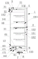
Fig. 1 is a front view of the device capable of cooling and heating simultaneously according to the present invention.
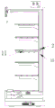
Fig. 2 is a cross-sectional view a-a of the apparatus of fig. 1 according to the present invention.
Fig. 3 is a cross-sectional view B-B of the apparatus of fig. 1 according to the present invention.
Fig. 4 is a cross-sectional view of the apparatus of fig. 1 according to the present invention, taken along line C-C.
Fig. 5 is the whole state diagram of the air curtain cabinet when the air door is opened.
Fig. 6 is the whole state diagram of the air curtain cabinet when the air door is closed.
Fig. 7 is a schematic view of the overall structure of the middle partition shelf of the present invention.
Fig. 8 is a sectional structure view of the middle partition shelf of the present invention.
Fig. 9 is a connection structure diagram of the heating wire, the heat preservation cotton and the baffle fixing side plate of the utility model.
In the figure: 1. a cabinet body; 101. a back panel; 102. a threading plate; 103. a separator bracket; 2. a damper; 3. a light box; 31. pulling the curtain; 32. an illuminating lamp; 4. an electrical control room; 5. an air deflector; 51. an air deflector support plate; 6. a fan I; 61. a fan II; 7. a condenser; 8. a compressor; 9. an evaporator; 10. a shelf of spacer layers; 1001. the clapboard fixes the side plate; 1002. heating wires; 11. a middle clapboard layer frame; 110. a middle partition plate; 111. a movable laminate; 112. wire outgoing; 113. a handle; 114. an upper cover plate; 115. heat preservation cotton; 116. a telescopic connecting rod; 117. rotating the connecting shaft; 118. a chute; 119. a slide rail; 12. an air return opening; 131. foaming; 132. post foaming; 133. foaming at the bottom; 141. an air curtain vent I; 142. an air curtain vent II; 151. an air duct I; 152. an air duct II; 161. a bottom air deflector I; 162. a bottom air deflector II; 171. a heating pipe bracket I; 172. and a heating pipe bracket II.
Detailed Description
The technical solutions in the embodiments of the present invention will be described clearly and completely with reference to the accompanying drawings in the embodiments of the present invention, and it is obvious that the described embodiments are only some embodiments of the present invention, not all embodiments. Based on the embodiments in the present invention, all other embodiments obtained by a person skilled in the art without creative work belong to the protection scope of the present invention.
EXAMPLE 1 Equipment capable of refrigerating and heating simultaneously
As shown in FIG. 1, the utility model provides a but equipment of simultaneous cooling and heating, the heater strip 1002 is adopted in heating, and the refrigeration adopts forced air cooling, the direct air cooling of refrigerating unit formula and directly cools off the refrigeration mode. When a user adjusts the functions of cooling and heating simultaneously, the upper cover plate 114 of the middle partition plate 111 needs to be pulled out, the air door 2 is closed, the upper part of the air duct II 152 is closed, and switching is carried out through a physical, mechanical or electrical automatic device. The equipment comprises a cabinet body 1, a lamp box 3, an electric control room 4, an air deflector 5, a fan, a refrigerating unit and a heating device, a lamp box 3 is arranged at the top of the cabinet body 1, an electric control room 4 is arranged at the upper part of the lamp box 3, the bottom end in the cabinet body 1 is provided with a wind deflector 5, a fan I6, a fan II 61, a condenser 7, a compressor 8, an evaporator 9 and other refrigerating machine components and heating devices, the heating device comprises a heating pipe arranged in a heating pipe bracket at the bottom and a heating wire arranged in a clapboard layer frame, the air deflector 5 comprises a bottom air deflector I161 and a bottom air deflector II 162, a heating pipe bracket I171 and a heating pipe bracket II 172 are arranged on one side of the air guiding surfaces of the bottom air deflector I161 and the bottom air deflector II 162, the lamp box 3, the fan, the refrigerating unit and the heating device are all electrically connected with the electric control room 4.
Partition plate supports 103 are mounted on the left side and the right side in the cabinet body 1, threading plates 102 are mounted on a rear back plate 101 in the cabinet body 1, partition plate layer frames 10 are arranged in the partition plate supports 103 at intervals, a middle partition plate layer frame 11 (shown in figure 7) is mounted in the middle, an air return opening 12 is arranged between the bottom and an air guide plate 5 at the bottom of the cabinet body 1, the partition plate layer frames 10 can be placed on the partition plate supports 103 as required (for example, partition plate layer frame mounting holes on the left side and the right side are formed in the cabinet body in figure 1), the partition plate layer frames 10 are fixedly connected with the inner side of the cabinet body 1 through partition plate fixing side plates 1001 (shown in figure 9), heating wires 1002 are wound in the partition plate layer frames 10, heat insulation cotton 115 is arranged above the heating wires 1002, and the electric heating wires 1002 are used for directly converting electric energy into heat energy. The electric heating wire 1002 is turned on to generate heat electrically. The electric heating has overload protection, when the heating temperature exceeds a set value, the overload protection carries out safety protection power-off, when the temperature is lower than the set value, the electric heating is automatically switched on and started, and the thermal protection is switched off.
An air duct is arranged between the rear back plate 101 and the rear shell of the cabinet body 1, the air duct comprises an air duct I151 and an air duct II 152, as shown in the attached drawings 2-4, rear foaming 132 is arranged between the air duct II 152 and the inner side of the cabinet body 1, upper foaming 131 is arranged on the inner side of the top end of the cabinet body 1, lower foaming 133 is arranged on the upper side of the condensation cabinet arranged at the lower end of the cabinet body 1, the foaming at the upper part, the lower part, the rear part and the like is a heat preservation effect, the intermediate partition plate layer frame 11 is fixed in the cabinet body 1, the intermediate partition plate layer frame 11 comprises an intermediate partition plate 110 and a drawable mechanism in sliding connection with the intermediate partition plate 110, the front end and the rear end of the intermediate partition plate 110 are provided with through chutes matched with the drawable mechanism, the drawable mechanism comprises a movable layer plate 111 and a telescopic connecting rod 116, the movable layer plate 111 comprises a sliding rail 119 and a sliding chute 118 arranged on the side of the movable layer plate 111, the sliding rail comprises heat insulation cotton 115 filled in the movable laminate 111 and an upper cover plate 114 arranged above the heat insulation cotton 115, wherein the upper cover plate 114 is the laminate on the movable laminate 111, one end of the upper cover plate 114 is provided with a handle 113 for facilitating drawing, and the upper cover plate has the functions that the laminate can be used as a shelf after being drawn out, and the sliding rail can be protected from being polluted; one end of the telescopic connecting rod 116 is hinged with the movable layer plate 111, the other end of the telescopic connecting rod is rotatably connected with the air door 2 through a rotating connecting shaft 117, heat insulation cotton 115 is arranged on the outer side of the telescopic connecting rod 116 and in the middle partition plate 110, and the heat insulation plates 115 have the functions of isolating the heat and the cold of the upper layer and the lower layer from being mutually connected and respectively insulating the heat of the upper layer and the lower layer; a heating wire 1002 is coiled in the upper layer of the central partition 110, and the outlet wire 112 of the heating wire 1002 is arranged outside the central partition.
The air ducts are provided with partition boards, air guide plates 5 and the like, the air guide plates 5 comprise a bottom air guide plate I161 and a bottom air guide plate II 162, and each layer of partition board in the device is provided with a heating wire 1002 for heating objects on each layer of partition board. The metal paper is arranged on the two sides of the heating wire 1002, so that heat can be better and more uniformly transferred to the partition plate; the heating wire 1002 outlet 112 on each layer of the partition layer shelf 10 is led to the upper electric control room 44 through the threading holes on the threading plate 102. The top of the cabinet body is also provided with an illuminating lamp 32 and a pull curtain 31, and the illuminating lamp 32 is used for illuminating; the curtain 31 functions as follows: firstly, at night, the user can pull down the pull curtain 31 to protect objects in the box and isolate dust and the like; secondly, the following steps: the pull curtain 31 can also block the entering of external cold air or hot air when pulled down, has the function of heat preservation, and the bottom of the cabinet body can be provided with casters.
An air curtain vent I141 and an air curtain vent II 142 are arranged on one side of the top of the cabinet body 1 far away from the electric control chamber 44, namely one side close to the cabinet body door, a bottom air return port 12 is arranged at the bottom, a fan circulates hot air in the whole cabinet body 1 to form an air curtain, and the first air curtain is used for isolating outside cold air; secondly, the fan accelerates the circulation of heat, so that the heat can reach each position in the cabinet body 1, the temperature of each area in the cabinet body 1 is balanced, and the phenomenon that the temperature of a certain position is too high or too low is prevented, specifically, a user places an object to be heated or frozen on the partition plate layer frame 10, selects a temperature mode and temperature setting, and the heating wire 1002 or the refrigerating unit works to provide heat or cold for the object. The bottom is provided with a fan, a heating rod (the shape is not limited to that shown in the figure), a refrigerating unit (an evaporator 9, a condenser 7, a compressor 8 and the like) and the fan. As shown in fig. 5, after the device is started, because the mode is simultaneous cooling and heating, the heating pipe on the heating pipe support i 171 and the heating wire 1002 on the lower partition plate layer frame 10 do not work, the heating pipe on the heating pipe support ii 172, the refrigerating unit and the upper part of the cabinet body, namely, the heating wire 1002 in the partition plate layer frame 10 above the middle partition plate layer frame 11, start working to generate heat and cold, after the fan is started, the heat is sent into the air duct ii 152, and the cold is sent into the air duct i 151; the heat in the air duct II 152 forms an air curtain through the air curtain ventilation opening II 142 at the top to isolate the external air. Air duct I151 is cooled down through evaporimeter 9 by the air that fan I6 absorbed the income, transports to air curtain vent I141, because the plywood is pulled out, and air door 2 is closed, and the cold volume in air duct I151 directly transports to the lower part region through the backplate vent, provides cold volume for lower floor's space. Air ducts (similar to top air ducts) can be added at the lower ends of the middle partition plate layer frames 11 to form air curtains to blow towards the inside of the cabinet body 1, circulation of cold energy is accelerated, the cold energy can reach each position in the cabinet body 1, the temperature of each area in the cabinet body 1 is balanced, and the phenomenon that the temperature of a certain part is too high or too low is prevented. The cold air curtain is combined with the back ventilation opening to work together.
The working principle is as follows: when the equipment is used as equipment for simultaneously refrigerating and heating, the expansion plate on the middle partition plate layer frame 11 is pulled out, as shown in fig. 6, at the moment, the equipment can be divided into an upper section and a lower section, wherein the upper section is a heating cabinet, and the lower section is a refrigerating cabinet, and the equipment works respectively. Install flexible slide or connecting rod 117 or electronic automatic device on intermediate bottom layer frame 11, connecting rod 117 is connected with air door 2, and when the baffle was pulled out, can drive air door 2 pivoting, changes the direction of air door 2, and when pulling out, air door 2 closed, and the part is closed on the I151 of wind channel, and the cold wind through I151 of wind channel blows in lower part region this moment, provides cold volume, cooling article for lower part region. The upper part of the device is used for heating, and heat is supplied to the device by the working of the heating wires 1002 on each layer of partition; because the upper part and the lower part of the middle partition plate layer frame 11 are respectively provided with a heating area and a refrigerating area, the partition plate and the lower part thereof are additionally provided with heat insulation cotton 115 to isolate the heat quantity and the cold quantity of the upper layer and the lower layer, and the two lower parts can achieve the purposes of heating and refrigerating. The middle partition plate layer frame 11 is provided with a slide rail, so that the telescopic plate can be conveniently pulled out.
Example 2 switching of the apparatus to the full refrigeration State
Unlike embodiment 1, this embodiment is used to describe the air curtain cabinet in which the apparatus is switched to the full cooling state.
When the user used the full refrigeration mode, heating pipe and heater strip 1002 stop work on the heating pipe support I171, the refrigerating unit work, pushed into intermediate bottom layer frame 11, and air door 2 was opened under telescopic link 116's effect this moment, and the cold volume in the wind channel I151 can be transported to top air curtain vent I141, blows cold volume down, combines together with the cold volume that the back vent came out, forms the refrigeration environment. The fan II 61 and the heating rod still work, and the air quantity forms an air curtain through the air duct II 152 and the air curtain ventilation opening II 142 to isolate external air.
The principle of refrigeration is as follows: the heating wires 1002 in the corresponding clapboard laminate are closed, and the work is stopped; the lower separator sheet may also be replaced with a conventional sheet without heating wires 1002. With the refrigeration unit, when the equipment works, the compressor 8 sucks the low-temperature and low-pressure refrigerant vapor generated by the evaporator 9 into the cylinder, the low-temperature and low-pressure refrigerant vapor is compressed by the compressor 8, and when the pressure is increased (the temperature is also increased) to be slightly higher than the pressure in the condenser 7, the high-pressure refrigerant in the cylinder is refrigerated to the vapor and is discharged into the condenser 7. The high-temperature and high-pressure refrigerant vapor in the condenser exchanges heat with air (or normal-temperature water) with lower temperature to be condensed into liquid refrigerant, and the liquid refrigerant is cooled (reduced in pressure) by an expansion valve and then enters the evaporator 9, absorbs the heat of the cooled object in the evaporator 9 and is vaporized. The cooled object is cooled and the refrigerant vapor is sucked by the compressor 8, so that a cycle is completed in the refrigeration system through four processes of compression, condensation, expansion and evaporation.
Example 3 switching of the plant to full heating State
Different from the embodiment 1, the embodiment is a heating device, when a user uses a full heating mode, the heating pipe on the heating pipe bracket i 171, the fan i 6 and the heating wire 1002 start to work, and the electric heating wire 1002 and the wind heat mode are adopted. The partition layer frames 10 in the device are provided with heating wires 1002, and when the device is used for heating, a power supply is directly switched on to work, and electric energy is converted into heat through the electric heating wires 1002. When heating is needed, a user modulates the temperature mode needed by the gear, and the electric heating wire 1002 is powered on to work. According to the temperature setting or gear required by the product, the heating wire 1002 works to heat the food stored in the cabinet body 1. The refrigerating unit stops working, the middle partition plate layer frame 11 is pushed in, the air door 2 is opened under the action of the telescopic connecting rod 116 at the moment, heat in the air channel I151 can be conveyed to the top air curtain ventilation opening I141, the heat is blown down, and the heat is combined with heat coming out of the back ventilation opening to form a heating environment. The heating wire 1002 on the partition shelves 10 is electrified to work to generate heat. Fan II 61 and heating rod II throw away work, and the amount of wind forms the air curtain through wind channel II 152, air curtain vent II 142, isolated outside air.
In addition, in the description of the present invention, it should be understood that the terms "center", "upper", "lower", "front", "rear", "left", "right", "vertical", "horizontal", "top", "bottom", "inner", "outer", "etc. indicate the orientation or positional relationship, and are merely for convenience of description of the present invention and simplification of description, and the description is mainly made with reference to fig. 1, and it is not intended to indicate or imply that the device or element referred to must have a specific orientation, be constructed and operated in a specific orientation, and thus, should not be construed as limiting the present invention.
The above-mentioned embodiments of the present invention do not limit the scope of the present invention. Any modification, equivalent replacement, and improvement made within the spirit and principle of the present invention should be included in the protection scope of the claims of the present invention.
Claims (8)
1. The utility model provides an equipment that can refrigerate simultaneously and heat, includes the cabinet body, lamp house, electric control room, aviation baffle, fan and refrigerating unit and heats the device, its characterized in that: the refrigerator comprises a cabinet body and is characterized in that a lamp box is mounted at the top of the cabinet body, an electric control chamber is arranged at the upper part of the lamp box, an air deflector, a fan, a refrigerating unit and a heating device are mounted at the bottom of the cabinet body, and the lamp box, the fan, the refrigerating unit and the heating device are all electrically connected with the electric control chamber; the left side and the right side in the cabinet body are provided with the partition plate brackets, and the back plate in the cabinet body is provided with the threading plate; the partition board bracket is internally provided with partition board layer frames at intervals, the middle part of the partition board bracket is provided with a middle partition board layer frame, an air return opening is arranged between the bottom of the partition board bracket and the air deflector at the bottom of the cabinet body, and an air channel is arranged between the rear back board and the rear shell of the cabinet body.
2. The apparatus for simultaneously cooling and heating according to claim 1, wherein: the middle clapboard layer frame comprises a middle clapboard and a drawable mechanism which is connected with the middle clapboard in a sliding way.
3. The apparatus capable of simultaneously cooling and heating according to claim 2, wherein: the drawable mechanism comprises a movable laminate and a telescopic connecting rod, the movable laminate can be drawn out, one end of the telescopic connecting rod is hinged with the movable laminate, and the other end of the telescopic connecting rod is rotatably connected with the air door through a rotating connecting shaft.
4. The apparatus for simultaneously cooling and heating according to claim 2, wherein: the front end and the rear end of the middle partition plate are provided with through sliding chutes matched with the drawable mechanisms.
5. The apparatus for simultaneously cooling and heating according to claim 1, wherein: the partition plate layer frame is fixedly connected with the cabinet body through the partition plate fixing side plate.
6. The apparatus for simultaneously cooling and heating according to claim 1, wherein: the refrigerating unit comprises a compressor, an evaporator and a condenser which are arranged at the bottom end of the interior of the cabinet body.
7. The apparatus for simultaneously cooling and heating according to claim 1, wherein: the heating device is a heating pipe arranged on a heating pipe bracket at the bottom end in the cabinet body and a heating wire arranged in the partition plate layer frame.
8. The apparatus for simultaneously cooling and heating according to claim 1, wherein: the top of the cabinet body is provided with an air curtain vent I and an air curtain vent II, and the bottom is provided with a bottom air return inlet.
Priority Applications (1)
| Application Number | Priority Date | Filing Date | Title |
|---|---|---|---|
| CN202120344744.0U CN214406693U (en) | 2021-02-04 | 2021-02-04 | Equipment capable of refrigerating and heating simultaneously |
Applications Claiming Priority (1)
| Application Number | Priority Date | Filing Date | Title |
|---|---|---|---|
| CN202120344744.0U CN214406693U (en) | 2021-02-04 | 2021-02-04 | Equipment capable of refrigerating and heating simultaneously |
Publications (1)
| Publication Number | Publication Date |
|---|---|
| CN214406693U true CN214406693U (en) | 2021-10-15 |
Family
ID=78024580
Family Applications (1)
| Application Number | Title | Priority Date | Filing Date |
|---|---|---|---|
| CN202120344744.0U Active CN214406693U (en) | 2021-02-04 | 2021-02-04 | Equipment capable of refrigerating and heating simultaneously |
Country Status (1)
| Country | Link |
|---|---|
| CN (1) | CN214406693U (en) |
Cited By (2)
| Publication number | Priority date | Publication date | Assignee | Title |
|---|---|---|---|---|
| CN114234553A (en) * | 2021-11-22 | 2022-03-25 | 长虹美菱股份有限公司 | Cold and warm dual-purpose commercial cabinet and control method |
| CN115177125A (en) * | 2022-07-19 | 2022-10-14 | 青岛海容商用冷链股份有限公司 | Semiconductor cold and hot display cabinet and control method thereof |
-
2021
- 2021-02-04 CN CN202120344744.0U patent/CN214406693U/en active Active
Cited By (3)
| Publication number | Priority date | Publication date | Assignee | Title |
|---|---|---|---|---|
| CN114234553A (en) * | 2021-11-22 | 2022-03-25 | 长虹美菱股份有限公司 | Cold and warm dual-purpose commercial cabinet and control method |
| CN115177125A (en) * | 2022-07-19 | 2022-10-14 | 青岛海容商用冷链股份有限公司 | Semiconductor cold and hot display cabinet and control method thereof |
| CN115177125B (en) * | 2022-07-19 | 2024-03-22 | 青岛海容商用冷链股份有限公司 | Semiconductor cold and hot display cabinet and control method thereof |
Similar Documents
| Publication | Publication Date | Title |
|---|---|---|
| CN214406693U (en) | Equipment capable of refrigerating and heating simultaneously | |
| WO2020253252A1 (en) | Air-conditioning all-in-one machine for kitchen | |
| JP2002168554A (en) | Showcase and open showcase | |
| CN112790557A (en) | Whole machine vertical refrigeration display cabinet with heat extraction device | |
| CN110296479A (en) | Air conditioner used in kitchen all-in-one machine | |
| CN110296481A (en) | Air conditioner used in kitchen all-in-one machine | |
| CN212521154U (en) | Energy-saving dual-purpose serving trolley | |
| CN2901158Y (en) | Cool air, warm air and drying clothes integrated machine | |
| CN208635447U (en) | A kind of cold and hot double-purpose baking room | |
| CN2269136Y (en) | Improved two purpose display cabinet for cold and hot food | |
| CN206377910U (en) | Energy-saving cold storage cabinet | |
| CN106123445B (en) | A kind of energy-saving air-cooled | |
| CN213605551U (en) | Multilayer formula show cupboard that refrigeration effect is good | |
| CN207640016U (en) | A kind of cake cabinet | |
| CN112050528A (en) | Environment-friendly and energy-saving refrigeration equipment convenient to adjust | |
| CN109114858A (en) | A kind of anti-condensation household freezer | |
| CN206019121U (en) | A kind of energy-saving air-cooled | |
| CN201836996U (en) | Air-conditioner indoor unit with auxiliary electric heating structure | |
| CN219572420U (en) | Convertible cold-stored heating cabinet | |
| CN2697540Y (en) | Direct defrosting type freezer for commercial showing | |
| CN2831928Y (en) | Top cooling type display cabinet with curved glass | |
| CN220892672U (en) | Low-temperature air-cooled cooling cabinet | |
| CN219141254U (en) | Refrigerator with a refrigerator body | |
| CN202648286U (en) | Electric refrigerator capable of directly discharging heat | |
| CN220107354U (en) | Dual-power switching cabinet |
Legal Events
| Date | Code | Title | Description |
|---|---|---|---|
| GR01 | Patent grant | ||
| GR01 | Patent grant |