CN112790557A - Whole machine vertical refrigeration display cabinet with heat extraction device - Google Patents
Whole machine vertical refrigeration display cabinet with heat extraction device Download PDFInfo
- Publication number
- CN112790557A CN112790557A CN202110283519.5A CN202110283519A CN112790557A CN 112790557 A CN112790557 A CN 112790557A CN 202110283519 A CN202110283519 A CN 202110283519A CN 112790557 A CN112790557 A CN 112790557A
- Authority
- CN
- China
- Prior art keywords
- air
- refrigerating chamber
- cabinet body
- heat extraction
- extraction device
- Prior art date
- Legal status (The legal status is an assumption and is not a legal conclusion. Google has not performed a legal analysis and makes no representation as to the accuracy of the status listed.)
- Pending
Links
Images


Classifications
-
- A—HUMAN NECESSITIES
- A47—FURNITURE; DOMESTIC ARTICLES OR APPLIANCES; COFFEE MILLS; SPICE MILLS; SUCTION CLEANERS IN GENERAL
- A47F—SPECIAL FURNITURE, FITTINGS, OR ACCESSORIES FOR SHOPS, STOREHOUSES, BARS, RESTAURANTS OR THE LIKE; PAYING COUNTERS
- A47F3/00—Show cases or show cabinets
- A47F3/001—Devices for lighting, humidifying, heating, ventilation
-
- A—HUMAN NECESSITIES
- A47—FURNITURE; DOMESTIC ARTICLES OR APPLIANCES; COFFEE MILLS; SPICE MILLS; SUCTION CLEANERS IN GENERAL
- A47F—SPECIAL FURNITURE, FITTINGS, OR ACCESSORIES FOR SHOPS, STOREHOUSES, BARS, RESTAURANTS OR THE LIKE; PAYING COUNTERS
- A47F3/00—Show cases or show cabinets
- A47F3/04—Show cases or show cabinets air-conditioned, refrigerated
- A47F3/0404—Cases or cabinets of the closed type
- A47F3/0408—Cases or cabinets of the closed type with forced air circulation
-
- A—HUMAN NECESSITIES
- A47—FURNITURE; DOMESTIC ARTICLES OR APPLIANCES; COFFEE MILLS; SPICE MILLS; SUCTION CLEANERS IN GENERAL
- A47F—SPECIAL FURNITURE, FITTINGS, OR ACCESSORIES FOR SHOPS, STOREHOUSES, BARS, RESTAURANTS OR THE LIKE; PAYING COUNTERS
- A47F3/00—Show cases or show cabinets
- A47F3/04—Show cases or show cabinets air-conditioned, refrigerated
- A47F3/0404—Cases or cabinets of the closed type
- A47F3/0426—Details
Abstract
The invention discloses a complete machine vertical refrigeration display cabinet with a heat extraction device, which comprises a foaming cabinet body, a refrigeration system, the heat extraction device and a controller, wherein a refrigerating chamber is arranged on the inner side of the foaming cabinet body, and the front side of the refrigerating chamber is of an opening structure. The inside of the foaming cabinet body is provided with a circulating air cavity, an air outlet of the circulating air cavity is positioned at the top of the refrigerating chamber, and an air return inlet of the circulating air cavity is positioned at the bottom of the refrigerating chamber. The refrigerating system comprises a loop formed by sequentially connecting a refrigerant compression unit, a condenser and an evaporator, wherein the refrigerant compression unit is arranged at the rear side of the foaming cabinet body, the evaporator is arranged in the circulating air cavity, and one side of the evaporator is provided with an evaporation fan. The condenser is arranged above the top of the foaming cabinet body, and the heat extraction device is arranged above the condenser and comprises an air suction cover and an air exhaust pipeline. The invention adopts a new structural layout, reduces the height of the front edge, increases the display area and the volume, reduces the vibration noise, reduces the material cost, reduces the load of an indoor air conditioning system, saves energy and reduces consumption.
Description
Technical Field
The invention relates to the technical field of commercial refrigeration display cabinets, in particular to a complete machine vertical refrigeration display cabinet with a heat extraction device.
Background
The compressor and the condenser of the existing complete machine vertical refrigeration display cabinet are of an integrated unit structure, the compressor and the condenser are usually installed at the bottom or the top of the outer side of the cabinet body, the compressor and the condenser have certain heights, the refrigeration display cabinet is limited by the heights of the compressor and the condenser, the opening size of the refrigeration display cabinet is reduced, and meanwhile, the display area and the volume of the refrigeration display cabinet are also limited. On the other hand, the heat generated by the condenser is directly discharged indoors, so that the load of an indoor air conditioning system is increased, and the energy consumption is increased. Thus, further improvements and enhancements are needed in the art.
Disclosure of Invention
Aiming at the defects in the prior art, the invention aims to provide a complete machine vertical refrigeration display cabinet with a heat extraction device, which solves the problems that the size of an opening of a cabinet body is small, the display area and the volume are limited due to the height limitation of a compressor and a condenser, heat is directly discharged indoors, the load of an indoor air conditioning system is increased, and the energy consumption is increased.
In order to achieve the purpose, the invention adopts the technical scheme that:
the whole machine vertical refrigeration display cabinet with the heat extraction device comprises a foaming cabinet body, a refrigeration system, the heat extraction device and a controller, wherein a refrigerating chamber is arranged on the inner side of the foaming cabinet body, and the front side of the refrigerating chamber is of an opening structure.
The inside of the foaming cabinet body is provided with a circulating air cavity, an air outlet of the circulating air cavity is positioned at the top of the refrigerating chamber, and an air return inlet of the circulating air cavity is positioned at the bottom of the refrigerating chamber.
The refrigerating system comprises a loop formed by sequentially connecting a refrigerant compression unit, a condenser and an evaporator, wherein the refrigerant compression unit is arranged at the rear side of the foaming cabinet body, the evaporator is arranged in the circulating air cavity, and one side of the evaporator is provided with an evaporation fan.
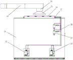
The condenser is arranged above the top of the foaming cabinet body, and the heat extraction device is arranged above the condenser and comprises an air suction cover and an air exhaust pipeline.
Further, the foaming cabinet body includes shell body, curb plate, the inside of shell body is equipped with bottom plate, backplate and roof, and the inner wall of shell body is fixed with the foaming layer.
The bottom plate is arranged on the lower portion of the outer shell, the top plate is arranged on the upper portion of the outer shell, the back plate is vertically arranged on the rear portion of the outer shell through the metal plate stand column, the upper end and the lower end of the back plate are respectively integrated with the back ends of the top plate and the bottom plate, and the circulating air cavity is located among the bottom plate, the back plate, the top plate and the foaming layer.
The refrigerating chamber is formed by matching the bottom plate, the back plate, the top plate and the two side plates.
Furthermore, a plurality of shelves are arranged on the rear side inside the refrigerating chamber, all the shelves are sequentially arranged at intervals from top to bottom and are detachably and fixedly connected with the metal plate stand columns through shelf supports respectively.
Furthermore, the air outlet is positioned on the front side of the top plate, and a honeycomb network is arranged on the air outlet;
the air return inlet is positioned on the front side of the bottom plate, an air return grille is arranged on the air return inlet, and the circulating air cavity and the refrigerating chamber form a circulating loop through the air outlet and the air return inlet.
Furthermore, the circulating air cavity is formed by sequentially connecting a bottom air duct, a back air duct and a top air duct end to end, the bottom air duct is positioned below the refrigerating chamber, the back air duct is positioned on the rear side of the refrigerating chamber, and the top air duct is positioned above the refrigerating chamber.
Furthermore, the refrigerant compression unit comprises a plurality of compressors, and an exhaust port of each compressor is respectively connected with an inlet pipeline of the condenser through a liquid storage tank and a throttling device in sequence.
The air inlet of each compressor is respectively connected with the outlet pipeline of the evaporator, and the evaporator is connected with the outlet pipeline of the condenser through an expansion valve arranged at the inlet of the evaporator.
Furthermore, a condensing fan is arranged on one side of the condenser, the air suction cover is of a horn mouth structure, the flaring end of the bottom of the air suction cover is positioned right above the condensing fan, and the upper end of the air suction cover is connected and communicated with one end of the exhaust pipeline through the air exhaust fan.
Furthermore, a glass door body is arranged on the front side of the foaming cabinet body, and a handle is installed on one side of the glass door body.
Furthermore, four corners of the bottom of the foaming cabinet body are respectively provided with a supporting leg.
By adopting the technical scheme, the invention has the beneficial technical effects that:
the compressor of the whole machine vertical refrigeration display cabinet is positioned on the outer side of the back of the cabinet body, the condenser and the condensing fan are positioned on the top of the cabinet body, and the welding pipeline is positioned on the back of the cabinet body, so that the front edge height can be reduced without occupying the bottom space of the cabinet body, and the display area and the volume of the cabinet body are increased. The cabinet body is provided with a plurality of compressors, and each compressor refrigerant circulating pipeline is independent, so that vibration is reduced, noise is reduced, and material cost can be saved.
Simultaneously, the cabinet body is placed at the scene and is accomplished cabinet body top installation heat extraction device, and the fan that induced drafts in the heat extraction device in summer is opened, and the heat that the condenser gived off is discharged outdoors through the ventiduct, reduces indoor air conditioning system load, and the fan is closed in the heat extraction device in winter, and the heat that the condenser gived off remains indoor, improves indoor temperature, accomplishes used heat effective utilization.
Drawings
Fig. 1 is a schematic structural diagram of a first implementation manner of the complete machine vertical refrigeration display cabinet.
Fig. 2 is a schematic structural diagram of a second implementation manner of the complete machine vertical refrigeration display cabinet.
FIG. 3 is a schematic view of the structure of the air flow direction inside the complete machine vertical refrigeration display cabinet.
Fig. 4 is a rear view schematic diagram of the whole vertical refrigeration display cabinet with a heat removal device according to the present invention.
Fig. 5 is a schematic top view of the whole vertical refrigeration display cabinet with heat removal device according to the present invention.
Fig. 6 is a schematic structural view of a glass door body according to a first embodiment of the present invention.
Fig. 7 is a schematic structural view of a second embodiment of the present invention after a glass door body is provided.
Detailed Description
The invention is described in detail below with reference to the accompanying drawings:
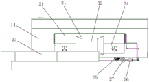
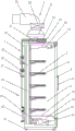
The foaming cabinet body 1 comprises an outer shell 14 and side plates, a bottom plate 15, a back plate 13 and a top plate 16 are arranged inside the outer shell 14, a foaming layer is fixed on the inner wall of the outer shell 14, and the heat insulation effect of the foaming layer on the inside of the foaming cabinet body 1 is utilized. Bottom plate 15 and roof 16 are respectively through sheet metal connector fixed mounting in the lower part and the upper portion of shell body 14, and backplate 13 is through the vertical fixed mounting in the rear portion of shell body of sheet metal stand, and the upper and lower both ends of backplate 13 are structure as an organic whole with the rear end of roof 16 and bottom plate 15 respectively. The number of the side plates is two, the side plates are respectively vertically arranged on the left side and the right side of the outer shell 14, the side plates are fixedly connected with the side faces of the outer shell 14, and the bottom plate 15, the back plate 13, the top plate 16 and the two side plates are matched to form the refrigerating chamber 11.
The inside of the foaming cabinet body 1 is provided with a circulating air cavity which is positioned between the bottom plate 15, the back plate 13, the top plate 16 and the foaming layer. The circulating air cavity is formed by sequentially connecting a bottom air duct 41, a back air duct 42 and a top air duct 43 end to end, the bottom air duct 41 is positioned below the refrigerating chamber 11, the back air duct 42 is positioned at the rear side of the refrigerating chamber 11, and the top air duct 43 is positioned above the refrigerating chamber 11.
The air outlet of the circulating air cavity is positioned at the top of the refrigerating chamber 11, and the air return inlet of the circulating air cavity is positioned at the bottom of the refrigerating chamber 11. Specifically, the air outlet is located on the front side of the top plate 16, the honeycomb network 44 is arranged on the air outlet, the return air inlet is located on the front side of the bottom plate 15, the return air grille 45 is arranged on the return air inlet, and the circulating air cavity and the refrigerating chamber 11 form a circulating loop through the air outlet and the return air inlet. In operation, cool air from the circulating air chamber is blown into the refrigerating compartment 11 through the top air duct 43 and the honeycomb duct 44, moves downward in the refrigerating compartment 11, and is returned to the bottom air duct 41 by the return air grille 45.
The rear side of the interior of the refrigerating chamber 11 is provided with a plurality of shelves 5, all the shelves 5 are arranged at intervals from top to bottom in sequence and are respectively detachably and fixedly connected with the sheet metal upright posts through a shelf bracket 51. The shelves 5 are used for placing cold chain food, so that the outside of the cold chain food is always kept at low temperature, the storage time of the cold chain food is prolonged, and the number of the shelves 5 and the distance between the shelves 5 can be determined according to the volume of the cold chain food.
The refrigerating system 2 includes a loop formed by sequentially connecting a refrigerant compression unit, a condenser 21 and an evaporator 22, the refrigerant compression unit is arranged at the rear side of the foaming cabinet body 1, the evaporator 22 is arranged in the circulating air cavity, and an evaporation fan 23 is arranged at one side of the evaporator. Condenser 21 sets up in foaming cabinet body 1 top, condenser 21's one side disposes condensation fan 24. Specifically, the evaporator 22 and the evaporation fan 23 are installed in the bottom air duct 41 (as shown in fig. 2), and at the same time, the evaporator 22 and the evaporation fan 23 may also be selectively installed in the back air duct 42 (as shown in fig. 1), the two installation structures are substantially the same, the whole vertical refrigeration display cabinet does not occupy the bottom space of the cabinet body structurally, the front height is reduced, and the display area and the volume are increased.
The compressors 25 can be arranged in one, two or more according to the length of the cabinet body, and the vibration of a single compressor is reduced by increasing the number of the compressors so as to reduce the noise of the system. The refrigerant compression unit of the embodiment comprises two compressors 25, the two compressors 25 are fixedly installed at the outer side of the back of the foaming cabinet body 1, and the number of the compressors is actually determined according to the length of the foaming cabinet body 1 or the volume of the refrigerating chamber 11. The exhaust of each compressor 25 is connected to the inlet line of the condenser 21 via a receiver tank 27 and a throttle device 26, respectively. The air inlet of each compressor 25 is connected to an outlet line of the evaporator 22, and the evaporator 22 is connected to an outlet line of the condenser 21 via an expansion valve 28 provided at an inlet thereof.
The refrigerant cycle starts from the exhaust of each compressor, enters the condenser 21 through a separate welded pipeline, then enters the evaporator 22 through the independent throttling device 26, finally returns to the filter bottle of each compressor through a gas return pipeline, and the compressor compresses the low-temperature and low-pressure refrigerant to complete the cycle. The compressors do not need to be connected in parallel, so that vibration is reduced, noise is reduced, and material cost can be reduced.
Parts which are not described in the invention can be realized by adopting or referring to the prior art.
In the description of the present invention, it is to be understood that the terms "central," "longitudinal," "lateral," "upper," "lower," "front," "rear," "left," "right," "vertical," "horizontal," "top," "bottom," "inner," "outer," and the like are used in the orientations and positional relationships indicated in the drawings for convenience in describing the present invention and for simplicity in description, and are not intended to indicate or imply that the referenced devices or elements must have a particular orientation, be constructed and operated in a particular orientation, and are therefore not to be considered limiting.
Furthermore, the terms "first" and "second" are used for descriptive purposes only and are not to be construed as indicating or implying relative importance.
It is to be understood that the above description is not intended to limit the present invention, and the present invention is not limited to the above examples, and those skilled in the art may make modifications, alterations, additions or substitutions within the spirit and scope of the present invention.
Claims (9)
1. A complete machine vertical refrigeration display cabinet with a heat extraction device comprises a foaming cabinet body, a refrigeration system, the heat extraction device and a controller, and is characterized in that a refrigerating chamber is arranged on the inner side of the foaming cabinet body, and the front side of the refrigerating chamber is of an opening structure;
a circulating air cavity is arranged in the foaming cabinet body, an air outlet of the circulating air cavity is positioned at the top of the refrigerating chamber, and an air return inlet of the circulating air cavity is positioned at the bottom of the refrigerating chamber;
the refrigerating system comprises a loop formed by sequentially connecting a refrigerant compression unit, a condenser and an evaporator, wherein the refrigerant compression unit is arranged at the rear side of the foaming cabinet body, the evaporator is arranged in the circulating air cavity, and one side of the evaporator is provided with an evaporation fan;
the condenser is arranged above the top of the foaming cabinet body, and the heat extraction device is arranged above the condenser and comprises an air suction cover and an air exhaust pipeline.
2. The whole machine vertical refrigeration display cabinet with the heat extraction device as claimed in claim 1, wherein the foaming cabinet body comprises an outer shell and side plates, a bottom plate, a back plate and a top plate are arranged inside the outer shell, and a foaming layer is fixed on the inner wall of the outer shell;
the bottom plate is arranged at the lower part of the outer shell, the top plate is arranged at the upper part of the outer shell, the back plate is vertically arranged at the rear part of the outer shell through the sheet metal stand column, the upper end and the lower end of the back plate are respectively integrated with the top plate and the rear end of the bottom plate, and the circulating air cavity is positioned among the bottom plate, the back plate, the top plate and the foaming layer;
the refrigerating chamber is formed by matching the bottom plate, the back plate, the top plate and the two side plates.
3. The whole machine vertical refrigeration display cabinet with the heat extraction device as claimed in claim 2, wherein a plurality of shelves are arranged at the rear side of the interior of the refrigerating chamber, all the shelves are arranged at intervals from top to bottom in sequence, and are detachably and fixedly connected with the sheet metal upright posts through shelf supports respectively.
4. The complete machine vertical refrigeration display cabinet with the heat removal device as recited in claim 2, wherein the air outlet is located at the front side of the top plate, and the air outlet is provided with a honeycomb network;
the air return inlet is positioned on the front side of the bottom plate, an air return grille is arranged on the air return inlet, and the circulating air cavity and the refrigerating chamber form a circulating loop through the air outlet and the air return inlet.
5. The whole machine vertical refrigeration display cabinet with the heat exhausting device as recited in claim 1, wherein the circulating air chamber is formed by connecting a bottom air duct, a back air duct and a top air duct end to end in sequence, the bottom air duct is located below the refrigerating chamber, the back air duct is located at the rear side of the refrigerating chamber, and the top air duct is located above the refrigerating chamber.
6. The whole machine vertical refrigeration display cabinet with the heat extraction device as recited in claim 1, wherein the refrigerant compression unit comprises a plurality of compressors, and an exhaust port of each compressor is respectively connected with an inlet pipeline of the condenser through a liquid storage tank and a throttling device in sequence;
the air inlet of each compressor is respectively connected with the outlet pipeline of the evaporator, and the evaporator is connected with the outlet pipeline of the condenser through an expansion valve arranged at the inlet of the evaporator.
7. The whole machine vertical refrigeration display cabinet with the heat extraction device as claimed in claim 1, wherein a condensation fan is disposed at one side of the condenser, the suction hood is in a bell mouth structure, the flared end of the bottom of the suction hood is located right above the condensation fan, and the upper end of the suction hood is connected and communicated with one end of the exhaust duct through the heat extraction fan.
8. The whole machine vertical refrigeration display cabinet with the heat extraction device as claimed in claim 1, wherein a glass door body is arranged at the front side of the foaming cabinet body, and a handle is mounted at one side of the glass door body.
9. The whole machine vertical refrigeration display cabinet with the heat extraction device as claimed in claim 1, wherein four corners of the bottom of the foaming cabinet body are respectively provided with a supporting leg.
Priority Applications (1)
| Application Number | Priority Date | Filing Date | Title |
|---|---|---|---|
| CN202110283519.5A CN112790557A (en) | 2021-03-17 | 2021-03-17 | Whole machine vertical refrigeration display cabinet with heat extraction device |
Applications Claiming Priority (1)
| Application Number | Priority Date | Filing Date | Title |
|---|---|---|---|
| CN202110283519.5A CN112790557A (en) | 2021-03-17 | 2021-03-17 | Whole machine vertical refrigeration display cabinet with heat extraction device |
Publications (1)
| Publication Number | Publication Date |
|---|---|
| CN112790557A true CN112790557A (en) | 2021-05-14 |
Family
ID=75817133
Family Applications (1)
| Application Number | Title | Priority Date | Filing Date |
|---|---|---|---|
| CN202110283519.5A Pending CN112790557A (en) | 2021-03-17 | 2021-03-17 | Whole machine vertical refrigeration display cabinet with heat extraction device |
Country Status (1)
| Country | Link |
|---|---|
| CN (1) | CN112790557A (en) |
Cited By (5)
| Publication number | Priority date | Publication date | Assignee | Title |
|---|---|---|---|---|
| CN113520104A (en) * | 2021-06-30 | 2021-10-22 | 青岛澳柯玛冷链集成有限公司 | Novel air curtain cabinet |
| CN113662396A (en) * | 2021-09-26 | 2021-11-19 | 江苏星星冷链科技有限公司 | Fruit and vegetable refrigeration and moisturizing system and display cabinet |
| CN113729446A (en) * | 2021-09-26 | 2021-12-03 | 江苏星星冷链科技有限公司 | Push-in type fruit and vegetable refrigeration display cabinet |
| CN113796705A (en) * | 2021-09-29 | 2021-12-17 | 江苏星星冷链科技有限公司 | Air curtain cabinet of water-cooling condensation system |
| CN113974382A (en) * | 2021-09-28 | 2022-01-28 | 青岛澳柯玛冷链集成有限公司 | Air curtain cabinet |
-
2021
- 2021-03-17 CN CN202110283519.5A patent/CN112790557A/en active Pending
Cited By (5)
| Publication number | Priority date | Publication date | Assignee | Title |
|---|---|---|---|---|
| CN113520104A (en) * | 2021-06-30 | 2021-10-22 | 青岛澳柯玛冷链集成有限公司 | Novel air curtain cabinet |
| CN113662396A (en) * | 2021-09-26 | 2021-11-19 | 江苏星星冷链科技有限公司 | Fruit and vegetable refrigeration and moisturizing system and display cabinet |
| CN113729446A (en) * | 2021-09-26 | 2021-12-03 | 江苏星星冷链科技有限公司 | Push-in type fruit and vegetable refrigeration display cabinet |
| CN113974382A (en) * | 2021-09-28 | 2022-01-28 | 青岛澳柯玛冷链集成有限公司 | Air curtain cabinet |
| CN113796705A (en) * | 2021-09-29 | 2021-12-17 | 江苏星星冷链科技有限公司 | Air curtain cabinet of water-cooling condensation system |
Similar Documents
| Publication | Publication Date | Title |
|---|---|---|
| CN112790557A (en) | Whole machine vertical refrigeration display cabinet with heat extraction device | |
| CN102072527B (en) | Lower air-out type packaged air conditioner | |
| CN215015595U (en) | Whole machine vertical refrigeration display cabinet with heat extraction device | |
| CN111023288A (en) | Integrated air conditioner | |
| CN212720022U (en) | Mobile air conditioner | |
| CN213984186U (en) | Freezer with external outlet pipe | |
| CN2811808Y (en) | Indoor unit of cabinet type air conditioner | |
| CN2893573Y (en) | Integrated multipurpose quick refrigerating machine | |
| CN2406175Y (en) | Domestic central air-conditioner with parallel flow condensator | |
| CN210688866U (en) | Refrigerating unit and refrigerator with same | |
| CN220582809U (en) | EPP overhead refrigerating unit | |
| CN220541234U (en) | Fresh air conditioner | |
| CN209826022U (en) | Refrigeration module for rear-inlet lower-outlet vending machine | |
| CN215597447U (en) | Indoor air conditioner | |
| CN216942597U (en) | Parking air conditioner | |
| CN216845297U (en) | Special air cooler for garlic cooling room | |
| CN217082731U (en) | Integrated vertical air conditioner | |
| CN200940908Y (en) | Outdoor communicating cabinet air conditioner | |
| CN2493877Y (en) | Moveable air conditioner | |
| CN220552009U (en) | Fresh air conditioner | |
| CN220728651U (en) | Main machine for refrigerating cabinet | |
| CN219775980U (en) | High-efficiency energy-saving air conditioner | |
| CN216080528U (en) | Freezer structure of side compressor unit | |
| CN219433383U (en) | Cold and warm integrated machine air conditioner | |
| CN220541233U (en) | Fresh air conditioner |
Legal Events
| Date | Code | Title | Description |
|---|---|---|---|
| PB01 | Publication | ||
| PB01 | Publication | ||
| SE01 | Entry into force of request for substantive examination | ||
| SE01 | Entry into force of request for substantive examination |