CN214316011U - Heat sink and electronic apparatus - Google Patents
Heat sink and electronic apparatus Download PDFInfo
- Publication number
- CN214316011U CN214316011U CN202022683633.0U CN202022683633U CN214316011U CN 214316011 U CN214316011 U CN 214316011U CN 202022683633 U CN202022683633 U CN 202022683633U CN 214316011 U CN214316011 U CN 214316011U
- Authority
- CN
- China
- Prior art keywords
- heat
- fins
- heat dissipation
- heat dissipating
- flow channel
- Prior art date
- Legal status (The legal status is an assumption and is not a legal conclusion. Google has not performed a legal analysis and makes no representation as to the accuracy of the status listed.)
- Active
Links
Images


Landscapes
- Cooling Or The Like Of Electrical Apparatus (AREA)
Abstract
The application discloses a radiator and an electronic device. The heat sink includes: a heat dissipation base plate; the first radiating fins and the second radiating fins are arranged on one side face of the radiating base plate at intervals in a staggered mode, first flow channel sections are formed between the first radiating fins and the second radiating fins, second flow channel sections are formed between every two adjacent first radiating fins, and the first flow channel sections on the two sides of each second radiating fin are communicated with the second flow channel sections formed between every two adjacent first radiating fins. The hot fluid passing through the two adjacent first flow channel sections can be introduced into the same second flow channel section, so that the two hot fluids are further mixed in the second flow channel section, and the heat dissipation efficiency of the radiator can be improved.
Description
Technical Field
The application relates to the technical field of self-cooling radiators, in particular to a radiator and electronic equipment.
Background
With the development of communication technology, the transmission speed is higher, the power output is higher, and the heat consumption of the unit volume of the system is increased from 15-20W/L to 30-40W/L. Generally, the tooth height of the heat dissipation tooth needs to be increased or the equipment volume needs to be increased, but the heat dissipation problem cannot be effectively solved due to the requirements of weight, volume and process limitation. Therefore, in the field of natural heat dissipation, it is highly desirable to improve the heat dissipation efficiency of the heat sink.
SUMMERY OF THE UTILITY MODEL
The application mainly provides a radiator and electronic equipment to solve the problem that the radiating efficiency of current radiator is lower.
In order to solve the technical problem, the application adopts a technical scheme that: a heat sink is provided. The heat sink includes: a heat dissipation base plate; the heat dissipation base plate comprises a heat dissipation base plate, a plurality of first heat dissipation fins and a plurality of second heat dissipation fins, wherein the plurality of first heat dissipation fins and the plurality of second heat dissipation fins are arranged on one side surface of the heat dissipation base plate in a staggered and spaced mode, first flow channel sections are formed between the first heat dissipation fins and the second heat dissipation fins, second flow channel sections are also formed between every two adjacent first heat dissipation fins, and the first flow channel sections on the two sides of each second heat dissipation fin are communicated with the second flow channel sections formed between every two adjacent first heat dissipation fins.
In some embodiments, the cross-sectional area of the second flow channel segment is greater than the cross-sectional area of the first flow channel segment in a direction perpendicular to the side of the heat-dissipating base plate.
In some embodiments, the first heat dissipation fins include a heat dissipation support portion and a heat dissipation extension portion, the heat dissipation support portion is connected between the heat dissipation extension portion and the heat dissipation base plate, the first flow channel section is formed between the heat dissipation support portion and the second heat dissipation fins, and the second flow channel section is formed between two adjacent heat dissipation extension portions.
In some embodiments, the heat dissipation support portion and the second heat dissipation fins are plate-shaped, and the width of the heat dissipation extension portion along the arrangement direction of the first heat dissipation fins and the second heat dissipation fins is greater than the width of the heat dissipation support portion.
In some embodiments, the height of the second heat dissipation fins along the direction perpendicular to the side surface of the heat dissipation base plate is greater than or equal to the distance between the heat dissipation extension portion and the heat dissipation base plate, an air outlet is formed between the heat dissipation extension portion and the second heat dissipation fins, and the first flow channel section is communicated with the second flow channel section through the air outlet.
In some embodiments, the heat dissipation extension portion includes an extension bottom plate and extension side plates disposed on two opposite sides of the extension bottom plate, the extension bottom plate is connected to one end of the heat dissipation support portion, which faces away from the heat dissipation bottom plate, the width of the extension bottom plate in the arrangement direction is greater than that of the heat dissipation support portion, the air outlet is formed between the extension side plate and the second heat dissipation fin, and the second flow channel section is formed between two adjacent extension side plates. In some embodiments, the first heat dissipation fins are provided with first air inlet notches, and the second heat dissipation fins are provided with second air inlet notches.
In some embodiments, the first air inlet notch and the second air inlet notch are arranged in an aligned manner.
In some embodiments, the first air inlet gaps are disposed on two sides of the first heat dissipation fins, the second air inlet gaps are disposed on two sides of the second heat dissipation fins, and the external air flow further enters the first flow channel segment along the first air inlet gaps and the second air inlet gaps.
In some embodiments, the height of the first radiator fins is greater than the height of the second radiator fins in a direction perpendicular to the side surface of the heat radiating base plate.
In order to solve the above technical problem, another technical solution adopted by the present application is: an electronic device is provided. The electronic device comprises the heat sink as described above.
The beneficial effect of this application is: in contrast to the state of the art, the present application discloses a heat sink and an electronic apparatus. Through forming first runner section and second runner section between first heat radiation fin and second heat radiation fin, the hot-fluid of two adjacent first runner sections can let in same second runner section for this two strands of hot-fluids further mix at second runner section, and because three sides of second runner section all communicate with outside air, then the air of joining in the heat exchange in the second runner section further increases by a wide margin, this two strands of hot-fluids and air further carry out the convection current at the second runner section, the radiating effect of radiator has been improved.
Drawings
In order to more clearly illustrate the embodiments of the present application or the technical solutions in the prior art, the drawings used in the description of the embodiments or the prior art will be briefly described below, it is obvious that the drawings in the following description are only some embodiments of the present application, and other drawings can be obtained by those skilled in the art without creative efforts, wherein:
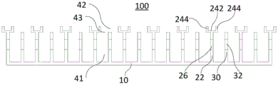
FIG. 1 is a schematic structural diagram of an embodiment of a heat sink provided herein;
FIG. 2 is a schematic diagram of a front view of the heat sink of FIG. 1;
FIG. 3 is a schematic front view of another heat sink provided herein;
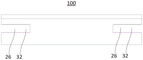
FIG. 4 is a side view of the heat sink of FIG. 1;
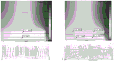
fig. 5 is a comparison graph of simulation analysis of the heat sink provided by the present application with respect to a temperature cloud map and a velocity vector map.
Detailed Description
The technical solutions in the embodiments of the present application will be clearly and completely described below with reference to the drawings in the embodiments of the present application, and it is obvious that the described embodiments are only a part of the embodiments of the present application, and not all of the embodiments. All other embodiments, which can be derived by a person skilled in the art from the embodiments given herein without making any creative effort, shall fall within the protection scope of the present application.
The terms "first", "second" and "third" in the embodiments of the present application are used for descriptive purposes only and are not to be construed as indicating or implying relative importance or implicitly indicating the number of technical features indicated. Thus, a feature defined as "first," "second," or "third" may explicitly or implicitly include at least one of the feature. In the description of the present application, "plurality" means at least two, e.g., two, three, etc., unless explicitly specifically limited otherwise. Furthermore, the terms "include" and "have," as well as any variations thereof, are intended to cover non-exclusive inclusions. For example, a process, method, system, article, or apparatus that comprises a list of steps or elements is not limited to only those steps or elements listed, but may alternatively include other steps or elements not listed, or inherent to such process, method, article, or apparatus.
Reference herein to "an embodiment" means that a particular feature, structure, or characteristic described in connection with the embodiment can be included in at least one embodiment of the application. The appearances of the phrase in various places in the specification are not necessarily all referring to the same embodiment, nor are separate or alternative embodiments mutually exclusive of other embodiments. It is explicitly and implicitly understood by one skilled in the art that the embodiments described herein can be combined with other embodiments.
Referring to fig. 1 to 2, fig. 1 is a schematic structural diagram of an embodiment of a heat sink 100, and fig. 2 is a schematic front structural diagram of the heat sink shown in fig. 1.
The heat sink 100 generally includes a heat sink base 10, a plurality of first heat dissipating fins 20 and a plurality of second heat dissipating fins 30, wherein the plurality of first heat dissipating fins 20 and the plurality of second heat dissipating fins 30 are staggered and spaced apart from each other on a side of the heat sink base 10.
The heat sink base plate 10, the first heat sink fins 20 and the second heat sink fins 30 are made of metal material with good heat conductivity, such as aluminum material or aluminum alloy, wherein the heat sink base plate 10 is mounted on an object to be cooled and conducts heat to the first heat sink fins 20 and the second heat sink fins 30, and the first heat sink fins 20 and the second heat sink fins 30 are arranged at intervals to reduce air resistance therebetween, so that heat on the fins and air in the interval spaces are fully contacted and mixed to exchange heat, thereby improving heat dissipation efficiency.
It should be noted that the heat sink 100 provided in the present application is a self-cooling heat sink, which mainly takes away heat from the heat sink 100 due to natural flow of the outside air, rather than a forced air-cooling heat sink that actively improves heat dissipation capacity by using a fan or the like.
The heat dissipating base plate 10 is shaped like a flat plate, and has a plurality of first heat dissipating fins 20 and a plurality of second heat dissipating fins 30 disposed on one side surface thereof, and the other side surface thereof is used for contacting an object to be dissipated. The heat dissipation base plate 10 is a flat plate with a moderate thickness, and the thickness of the heat dissipation base plate needs to consider reducing the thermal resistance of the heat dissipation base plate and considering the uniform heating of the whole base plate so as to ensure that the heat conduction efficiency of the heat dissipation base plate 10 is high.
The plurality of first heat dissipation fins 20 and the plurality of second heat dissipation fins 30 are vertically disposed on a side surface of the heat dissipation base plate 10, so as to increase contact areas between the first heat dissipation fins 20 and the second heat dissipation fins 30 and air, which is beneficial to improving heat dissipation efficiency.
In the present application, heat dissipation flow channels 40 are formed between the heat dissipation fins, wherein the heat dissipation flow channels 40 include a first flow channel section 41 and a second flow channel section 42. First flow channel sections 41 are formed between the first radiator fins 20 and the second radiator fins 30, second flow channel sections 42 are also formed between two adjacent first radiator fins 20, and the first flow channel sections 41 on two sides of the second radiator fins 30 are communicated with the second flow channel sections 42 formed between the first radiator fins 20 adjacent to the second radiator fins 30.
The external air flows into the heat dissipation channel 40 from both sides of the first and second heat dissipation fins 20 and 30, and flows through the first and second channel sections 41 and 42 in sequence to take away the heat on each heat dissipation fin.
Specifically, the hotter air near the discrete heat fins and the cooler air far from the discrete heat fins are fully stirred and mixed, so that the air involved in heat transfer is increased by times, the turbulence degree of the air flow in the first flow channel section 41 can be improved, the heat dissipation effect is improved, the hot fluid of two adjacent first flow channel sections 41 is further introduced into the same second flow channel section 42, so that the two hot fluids are further mixed in the second flow channel section 42, and because three sides of the second flow channel section 42 are both communicated with the outside air, the air involved in heat exchange in the second flow channel section 42 is further increased by a large margin, the two hot fluids and the air are further subjected to convection in the second flow channel section 42, and the heat dissipation effect of the heat sink 100 is improved.
Further, in a direction perpendicular to the side surface of the heat dissipation base plate 10, the cross-sectional area of the second flow channel segment 42 is larger than that of the first flow channel segment 41, so that the thermal fluid on both sides of the second heat dissipation fin 30 is sufficiently mixed with the air, and the heat dissipation effect is improved.
In this embodiment, the height of the first radiator fins 20 is greater than that of the second radiator fins 30 in a direction perpendicular to the side surface of the radiator support 10, so that a third flow path section 43 may be formed between two adjacent first radiator fins 20.
In other embodiments, the height of the first heat dissipating fins 20 may be less than or equal to the height of the second heat dissipating fins 30 in a direction perpendicular to the side surface of the heat dissipating base plate 10, and at least one notch is formed at an end of the second heat dissipating fins 30 away from the heat dissipating base plate 10, so that the third flow channel section 43 is formed by the notch of two adjacent first heat dissipating fins 20, which is not particularly limited in this application.
In this embodiment, the first heat sink fins 20 include a heat sink support portion 22 and a heat sink extension portion 24, the heat sink support portion 22 is connected between the heat sink extension portion 24 and the heat sink base plate 10, a first flow channel section 41 is formed between the heat sink support portion 22 and the second heat sink fins 30, and a second flow channel section 42 is formed between two adjacent heat sink extension portions 24.
In this embodiment, the heat dissipation support portion 22 and the second heat dissipation fins 30 are plate-shaped, and the width of the heat dissipation extension portion 24 along the arrangement direction of the first heat dissipation fins 20 and the second heat dissipation fins 30 is greater than the width of the heat dissipation support portion 22, so as to increase the heat dissipation area, and further, the distance between the heat dissipation support portion 22 and the second heat dissipation fins 30 is greater than the distance between the heat dissipation extension portion 24 and the second heat dissipation fins 30.
Therefore, the second heat dissipation fins 30 are disposed in a plate shape, which is beneficial to reducing the resistance of the hot air along the ascending path of the first flow channel section 41 and the second flow channel section 42, and further improving the heat dissipation efficiency of the heat sink 100.
In this embodiment, the height of the second heat sink fins 30 along the direction perpendicular to the side surface of the heat sink base plate 10 is greater than or equal to the distance between the heat dissipation extension portion 24 and the heat sink base plate 10, an air outlet 43 is formed between the heat dissipation extension portion 24 and the second heat sink fins 30, and the first flow channel section 41 is communicated with the second flow channel section 42 through the air outlet 43.
The width of the heat dissipation extension 24 in the arrangement direction of the first and second heat dissipation fins 20 and 30 is greater than the width of the heat dissipation support 22, and the cross-sectional area of the air outlet 43 in the direction perpendicular to the side surface of the heat dissipation base plate 10 is smaller than the cross-sectional areas of the first and second flow channel sections 41 and 42.
Specifically, the cross-sectional area of the heat dissipation flow channel 40 is changed at the junction of the first flow channel section 41 and the air outlet 43, and the cross-sectional area of the air flow is reduced, so that the flow velocity of the air flow entering the second flow channel 42 through the air outlet 43 is increased, the turbulence degree of the air flow is further increased, the mixing of cold air and hot air is accelerated, the air involved in heat transfer is greatly increased, and the heat dissipation effect is greatly improved.
In other embodiments, the height of the second heat dissipation fins 30 in the direction perpendicular to the side surface of the heat dissipation base plate 10 may also be smaller than the distance between the heat dissipation extension 24 and the heat dissipation base plate 10, which is not particularly limited in this application.
In the present embodiment, the heat dissipation extension portion 24 is U-shaped to increase the heat dissipation area, and the transfer path of the hot air is changed to facilitate the formation of turbulent flow, enhance heat dissipation, and improve heat dissipation efficiency. Specifically, the heat dissipation extension portion 24 includes an extension bottom plate 242 and extension side plates 244 disposed on two opposite sides of the extension bottom plate 242, the extension bottom plate 242 is connected to one end of the heat dissipation support portion 22 away from the heat dissipation bottom plate 10, the width of the extension bottom plate 242 in the arrangement direction is greater than the width of the heat dissipation support portion 22, an air outlet 43 is formed between the extension side plate 244 and the second heat dissipation fin 30, and the third flow channel section 43 is formed between two adjacent extension side plates 244.
By arranging the extension base plate 242 at one end of the heat dissipation support portion 22, and the width of the extension base plate 242 in the arrangement direction is greater than that of the heat dissipation support portion 22, the transfer path of the hot air is changed to facilitate the formation of turbulence, so that the hotter air adjacent to the surfaces of the first and second heat dissipation fins 20 and 30 is fully stirred and mixed with the cooler air farther from the surfaces of the first and second heat dissipation fins 20 and 30, and further, the air involved in heat convection is greatly increased, and the heat dissipation effect is greatly increased; the heat dissipation extension 24 further includes extension side plates 244 disposed on two opposite sides of the extension bottom plate 242, so as to relatively increase the heat dissipation area and further improve the heat dissipation effect.
In the embodiment, the extension side plate 244 is vertically connected to the extension bottom plate 242, and the extension side plate 244 and the second heat dissipation fins 30 are disposed at equal intervals, that is, the cross-sectional area of the air outlet 43 is regular, so that the resistance on the rising path of the hot air can be further reduced, and the heat dissipation efficiency of the heat sink 100 can be further improved.
Optionally, the extension side plate 244 may be connected to the extension bottom plate 242 in an inclined manner, so that the length of the extension side plate 244 may be relatively increased, and thus the heat dissipation area may be increased.
Alternatively, as shown in fig. 3, the heat dissipation extension portions 24 may also be V-shaped, a second flow channel section 42 is formed between the V-shaped heat dissipation extension portions 24, and the second heat dissipation fins 30 are disposed in a plate shape, which may also increase the heat dissipation area. The heat dissipating extension 24 may also have other shapes, and the present application is not limited thereto.
In other embodiments, the first radiator fins 20 may have a plate shape, and the second radiator fins 30 include the radiator support portion 22 and the radiator extension portion 24, and the height of the first radiator fins 20 is greater than that of the second radiator fins 30 in a direction perpendicular to the side surface of the radiator base plate 10.
Referring to fig. 4, fig. 4 is a schematic side view of the heat sink shown in fig. 1. In this embodiment, the first heat dissipation fins 20 are provided with the first air inlet notches 26, and the second heat dissipation fins 30 are provided with the second air inlet notches 32, so as to increase the natural air inlet contact area of the heat sink 100.
The first air inlet notches 26 and the second air inlet notches 32 are arranged in an aligned mode, so that the first air inlet notches 26 and the second air inlet notches 32 are communicated with each other, the contact area of each fin and cold air is increased, more heat is taken away, and the heat dissipation effect is improved.
The first air inlet notches 26 are disposed at both sides of the first radiator fins 20, the second air inlet notches 32 are disposed at both sides of the second radiator fins 30, and the external air flow further enters the first flow channel section 41 along the first air inlet notches 26 and the second air inlet notches 32.
The first air inlet notches 26 are disposed at both sides of the heat dissipation support portion 22, the second air inlet notches 32 are disposed opposite to the first air inlet notches 26, and the second air inlet notches 32 are disposed at both sides of the second heat dissipation fins 30, so that air outside the heat sink 100 can enter the middle portion between the first heat dissipation fins 20 and the second heat dissipation fins 30 through the first air inlet notches 26 and the second air inlet notches 32, so as to improve the contact amount of cold air at the middle heat dissipation flow passage 40 between the first heat dissipation fins 20 and the second heat dissipation fins 30, thereby improving the heat dissipation efficiency.
Referring to fig. 5, fig. 5 is a simulation analysis comparison diagram of the heat sink 100 provided by the present application with respect to a temperature cloud diagram and a velocity vector diagram, wherein the heat sink 100 on the left side is not provided with the first air inlet notch 26 and the second air inlet notch 32, and the heat sink 100 on the right side is provided with the first air inlet notch 26 and the second air inlet notch 32. As can be seen from fig. 4, in the left radiator 100, the arrow indicating the flow speed of the wind in the heat dissipation flow channel 40 in the central region is relatively sparse, and the wind speed in the central region indicates that the wind speed is relatively slow, and the cold air is hardly contacted here. The temperature in the middle area thereof is also higher; in the right radiator 100, the heat dissipation flow channel 40 in the middle area represents that the arrows of the wind speed marks are denser, the mark middle area contacts more cold air, the temperature in the middle area is lower, and the heat dissipation efficiency of the right radiator 100 relative to the left radiator is higher. It can be seen that by providing the first air inlet notch 26 and the second air inlet notch 32, the natural air outside can be effectively promoted to flow to the middle region of the heat dissipation channel 40, the cold air contact amount (air volume) of the middle region is increased, and the heat dissipation effect is effectively improved.
A conventional heat sink includes a base plate and a plurality of heat dissipation fins disposed on one side of the base plate, wherein the heat dissipation fins are flat. The present application thus provides heat sink 100 with advantages over conventional heat sinks, including: 1) under the condition of not increasing the weight and the structural volume, the heat dissipation capacity of the heat radiator can be effectively improved; 2) under the condition of the same heat dissipation capacity, the weight and the volume of the product can be effectively controlled, and the product is small and light compared with the traditional heat radiator.
Based on this, the present application also provides an electronic device, which includes the heat sink 100 as described above. The electronic apparatus includes a functional component and a heat sink 100, the heat sink 100 being mounted on the functional component to dissipate heat of the functional component. The functional component may be a processor or a circuit board or other energy consuming component.
By forming the first flow channel section and the second flow channel section between the first radiating fins and the second radiating fins, hot fluid of two adjacent first flow channel sections can be introduced into the same second flow channel section, so that the two hot fluids are further mixed in the second flow channel section, and three sides of the second flow channel section are communicated with outside air, so that air participating in heat exchange in the second flow channel section is further greatly increased, the two hot fluids and the air are further subjected to convection in the second flow channel section, and the radiating effect of the radiator is improved.
The above description is only an example of the present application and is not intended to limit the scope of the present application, and all modifications of equivalent structures and equivalent processes, which are made by the contents of the specification and the drawings, or which are directly or indirectly applied to other related technical fields, are intended to be included within the scope of the present application.
Claims (11)
1. A heat sink, comprising:
a heat dissipation base plate;
the heat dissipation base plate comprises a heat dissipation base plate, a plurality of first heat dissipation fins and a plurality of second heat dissipation fins, wherein the plurality of first heat dissipation fins and the plurality of second heat dissipation fins are arranged on one side surface of the heat dissipation base plate in a staggered and spaced mode, first flow channel sections are formed between the first heat dissipation fins and the second heat dissipation fins, second flow channel sections are also formed between every two adjacent first heat dissipation fins, and the first flow channel sections on the two sides of each second heat dissipation fin are communicated with the second flow channel sections formed between every two adjacent first heat dissipation fins.
2. The heat sink of claim 1, wherein the second flow channel segment has a cross-sectional area greater than a cross-sectional area of the first flow channel segment in a direction perpendicular to the side of the heat sink base plate.
3. The heat sink as claimed in claim 1, wherein the first heat dissipating fins comprise a heat dissipating support portion and a heat dissipating extension portion, the heat dissipating support portion is connected between the heat dissipating extension portion and the heat dissipating base plate, the first flow channel section is formed between the heat dissipating support portion and the second heat dissipating fins, and the second flow channel section is formed between two adjacent heat dissipating extension portions.
4. The heat sink as claimed in claim 3, wherein the heat dissipating support and the second heat dissipating fins are plate-shaped, and the heat dissipating extension has a width in the arrangement direction of the first heat dissipating fins and the second heat dissipating fins larger than that of the heat dissipating support.
5. The heat sink as claimed in claim 4, wherein the height of the second heat dissipating fins along the direction perpendicular to the side surface of the heat dissipating base plate is greater than or equal to the distance between the heat dissipating extension and the heat dissipating base plate, an air outlet is formed between the heat dissipating extension and the second heat dissipating fins, and the first flow channel section communicates with the second flow channel section through the air outlet.
6. The heat sink as claimed in claim 5, wherein the heat dissipating extension portion includes an extension bottom plate and extension side plates disposed at two opposite sides of the extension bottom plate, the extension bottom plate is connected to an end of the heat dissipating support portion facing away from the heat dissipating bottom plate, a width of the extension bottom plate along the arrangement direction is greater than a width of the heat dissipating support portion, the air outlet is formed between the extension side plate and the second heat dissipating fin, and the second flow channel section is formed between two adjacent extension side plates.
7. The heat sink as claimed in claim 1, wherein the first heat dissipating fins are provided with first air inlet notches, and the second heat dissipating fins are provided with second air inlet notches.
8. The heat sink of claim 7, wherein the first air inlet notch and the second air inlet notch are aligned.
9. The heat sink as claimed in claim 8, wherein the first air inlet notches are disposed on both sides of the first heat dissipating fins, the second air inlet notches are disposed on both sides of the second heat dissipating fins, and the external air flow further enters the first flow channel section along the first air inlet notches and the second air inlet notches.
10. The heat sink as claimed in claim 1, wherein the first radiator fins have a height greater than that of the second radiator fins in a direction perpendicular to the side surface of the heat radiating base plate.
11. An electronic device characterized in that it comprises a heat sink according to any one of claims 1 to 10.
Priority Applications (1)
| Application Number | Priority Date | Filing Date | Title |
|---|---|---|---|
| CN202022683633.0U CN214316011U (en) | 2020-11-18 | 2020-11-18 | Heat sink and electronic apparatus |
Applications Claiming Priority (1)
| Application Number | Priority Date | Filing Date | Title |
|---|---|---|---|
| CN202022683633.0U CN214316011U (en) | 2020-11-18 | 2020-11-18 | Heat sink and electronic apparatus |
Publications (1)
| Publication Number | Publication Date |
|---|---|
| CN214316011U true CN214316011U (en) | 2021-09-28 |
Family
ID=77842400
Family Applications (1)
| Application Number | Title | Priority Date | Filing Date |
|---|---|---|---|
| CN202022683633.0U Active CN214316011U (en) | 2020-11-18 | 2020-11-18 | Heat sink and electronic apparatus |
Country Status (1)
| Country | Link |
|---|---|
| CN (1) | CN214316011U (en) |
-
2020
- 2020-11-18 CN CN202022683633.0U patent/CN214316011U/en active Active
Similar Documents
| Publication | Publication Date | Title |
|---|---|---|
| CN110164835B (en) | Manifold type micro-channel micro-radiator with complex structure | |
| CN104167399B (en) | The complicated microchannel micro heat exchanger of dislocation | |
| US20140151012A1 (en) | Heat sink with staggered heat exchange elements | |
| CN211831654U (en) | Efficient liquid cooling plate and equipment | |
| CN212211744U (en) | Radiator and communication equipment | |
| CN215418156U (en) | Microchannel copper-aluminum composite relieving liquid cooling radiator | |
| CN209896047U (en) | Manifold type micro-channel micro radiator with complex structure | |
| CN211125625U (en) | Liquid cooling heat dissipation assembly, liquid cooling heat dissipation device and power electronic equipment | |
| CN112928082A (en) | Liquid cooling plate and power module | |
| CN220123320U (en) | Liquid cooling radiator | |
| CN214316011U (en) | Heat sink and electronic apparatus | |
| CN113543575A (en) | Radiator and communication equipment | |
| CN116525566A (en) | Microchannel cooling fin and microchannel radiator | |
| CN217444376U (en) | Heat dissipation bottom plate, power module, electronic equipment and vehicle | |
| CN215177187U (en) | Adopt 3D heat dissipation module of samming plate structure | |
| CN101330814B (en) | Radiating device | |
| Hu et al. | Heat Transfer Analysis of Heat Sink Modules for High-Power Led Equipment | |
| CN105353847A (en) | CPU application oriented metal-polymer composite micro-structure heat dissipator structure | |
| CN221305738U (en) | Inverter with a power supply | |
| CN112333974B (en) | Fin radiator with good turbulence effect | |
| CN213755502U (en) | Copper-aluminum combined radiator | |
| CN221056886U (en) | Split type water-cooling industrial personal computer | |
| CN214502170U (en) | Plate radiator of high-efficient heat conduction | |
| CN212390895U (en) | Novel vortex and turbulent flow fin structure | |
| CN218499500U (en) | Heat dissipation device |
Legal Events
| Date | Code | Title | Description |
|---|---|---|---|
| GR01 | Patent grant | ||
| GR01 | Patent grant |