CN214264819U - Stud processing combined machine tool - Google Patents
Stud processing combined machine tool Download PDFInfo
- Publication number
- CN214264819U CN214264819U CN202023310430.3U CN202023310430U CN214264819U CN 214264819 U CN214264819 U CN 214264819U CN 202023310430 U CN202023310430 U CN 202023310430U CN 214264819 U CN214264819 U CN 214264819U
- Authority
- CN
- China
- Prior art keywords
- clamping
- horizontal line
- machine tool
- sides
- combined machine
- Prior art date
- Legal status (The legal status is an assumption and is not a legal conclusion. Google has not performed a legal analysis and makes no representation as to the accuracy of the status listed.)
- Active
Links
Images


Abstract
The utility model provides a stud processing combined machine tool, includes two clamping device that distribute along horizontal line section, the position that corresponds a clamping device in the both sides of horizontal line section all has set firmly chamfer processingequipment, the position that corresponds another clamping device in the both sides of horizontal line section all has set firmly screw thread roll forming device, the position at horizontal line section both ends is provided with loading attachment and unloader respectively, reciprocating motion is provided with elevating system in clamping device's top and between loading attachment and unloader, install the clamping jaw on elevating system. Two machining positions are arranged on the same machine tool for parallel operation, so that the production efficiency is high; the lifting mechanism which moves back and forth between the feeding device and the discharging device drives the clamping jaw to grab and move the workpiece, and the two clamping devices are matched to fix and position the processed workpiece, so that the processed workpiece is subjected to chamfering grinding, drilling and thread processing, the automation degree is high, and the labor cost is saved.
Description
Technical Field
The utility model relates to a stud processing technology field, concretely relates to stud processing combined machine tool.
Background
At present, bolts are mostly machined by a single machine such as a turning machine or a thread rolling machine, the stud bolts can be machined into finished products only by multiple times of clamping and manual turnover, machining efficiency is low, the number of devices is large, and occupied space is large.
SUMMERY OF THE UTILITY MODEL
To the problem among the prior art, the utility model provides a stud processing combined machine tool.
The utility model provides a stud processing combined machine tool, includes two clamping device that distribute along horizontal line segment the both sides of horizontal line segment correspond one clamping device's position has all set firmly chamfer processingequipment the both sides of horizontal line segment correspond another clamping device's position has all set firmly screw thread roll extrusion processingequipment the position at horizontal line segment both ends is provided with loading attachment and unloader respectively clamping device's top is just in reciprocating motion is provided with elevating system between loading attachment and the unloader install the clamping jaw on the elevating system.
The utility model discloses a theory of operation: the clamping jaws take the stud bolts out of the feeding device, and then the stud bolts are sequentially placed on two clamping devices for processing under the moving and lifting actions of the lifting mechanism, wherein the clamping devices are used for fixing the positions of the stud bolts so as to process the stud bolts; after the stud bolt is machined, the machined stud bolt is moved to the blanking device through the clamping jaw.
Further: the clamping device comprises a base and a driving mechanism arranged on the base, two split clamping plates are arranged at the positions, located on the two sides of the horizontal line section, of the base, clamping ports are formed in the positions, located between the two clamping plates, of the two clamping plates, the clamping ports located on the two clamping plates are in butt joint to form a circular holding hole, and the direction of the holding hole is perpendicular to the horizontal line section; the two splints are linked with the driving mechanism and are arranged in an opening and closing manner, and the driving mechanism for driving the two splints to be arranged in the opening and closing manner is conventional technology in the field, and is not described herein again.
Further: and the feeding device and the discharging device are both horizontally arranged conveying belts.
Further: the lifting mechanism comprises a mounting seat, the upper part of the mounting seat is slidably mounted on a fixedly arranged linear rack, the linear rack is arranged in parallel with the horizontal line segment, a servo motor is mounted on the mounting seat, a driving shaft of the servo motor is fixedly sleeved with a gear, and the gear is meshed with the linear rack; the lower part of the mounting seat is fixedly provided with a telescopic cylinder, and the clamping jaw is fixedly arranged at the end part of the lower end of a telescopic rod vertically arranged on the telescopic cylinder. The lifting structure and the horizontal moving structure of the driving clamping jaw are conventional technical structures, and a schematic diagram is not drawn here.
Further: the clamping jaw includes fixing base and two relative arc splint that set up, the fixing base is overlapped admittedly on the telescopic link vertical screw rod is installed to the fixing base internal rotation, the upper end tip of screw rod with fixed mounting's second servo motor links on the fixing base the equal screw-thread fit in both sides of the lower extreme tip of screw rod has the second gear, the second gear rotates to be installed on the fixing base, two arc splint correspond fixed connection respectively on the second gear of screw rod both sides. The second servo motor drives the screw rod to rotate, so that the two arc-shaped clamping plates are driven to be opened and closed, and when the two arc-shaped clamping plates are closed, the stud bolts are horizontally grabbed.
The utility model has the advantages that: two machining positions are arranged on the same machine tool for parallel operation, so that the production efficiency is high; the lifting mechanism which moves back and forth between the feeding device and the discharging device drives the clamping jaw to grab and move the workpiece, and the two clamping devices are matched to fix and position the processed workpiece, so that the processed workpiece is subjected to chamfering grinding, drilling and thread processing, the automation degree is high, and the labor cost is saved.
Drawings
Fig. 1 is a schematic top view of the present invention;
FIG. 2 is a schematic cross-sectional view of AA in FIG. 1;
FIG. 3 is a schematic cross-sectional view of BB in FIG. 1;
FIG. 4 is a schematic cross-sectional view of the CC of FIG. 1;
fig. 5 is a schematic view of a driving structure of the middle clamping jaw of the present invention.
In the figure, 1, a feeding device; 2. a chamfering device; 3. a thread rolling device; 4. a blanking device; 51. a base; 52. a splint; 60. a clamping jaw; 601. a second gear; 602. a screw; 603. an arc-shaped splint; 61. a fixed seat; 62. a lifting mechanism; 63. a linear rack.
Detailed Description
The present invention will be described in detail with reference to the accompanying drawings. Reference will now be made in detail to embodiments of the present invention, examples of which are illustrated in the accompanying drawings, wherein like reference numerals refer to the same or similar elements or elements having the same or similar function throughout. The embodiments described below by referring to the drawings are exemplary only for explaining the present invention, and should not be construed as limiting the present invention. The terms of left, middle, right, upper and lower directions in the examples of the present invention are only relative concepts or reference to the normal use status of the product, and should not be considered as limiting.
The utility model provides a stud processing combined machine tool, as shown in fig. 1, fig. 2 and fig. 3, includes two clamping device that distribute along horizontal line segment the both sides of horizontal line segment correspond one clamping device's position all has set firmly chamfer processingequipment 2 horizontal line segment's both sides correspond another clamping device's position all has set firmly screw thread roll extrusion processingequipment 3 the position at horizontal line segment both ends is provided with loading attachment 1 and unloader 4 respectively clamping device's top just reciprocating motion is provided with elevating system 62 between loading attachment 1 and the unloader 4, loading attachment 1 and unloader 4 are the conveyer belt of level setting install the clamping jaw on elevating system 62.
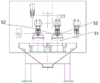
As shown in fig. 4, the clamping device includes a base 51 and a driving mechanism installed on the base 51, two split type clamping plates 52 are respectively disposed on the base 51 at two sides of the horizontal line segment, clamping interfaces are respectively disposed on the two clamping plates 52 at positions between the two clamping plates, the clamping interfaces on the two clamping plates 52 are butted together to form a circular holding hole, and the holding hole is oriented perpendicular to the horizontal line segment; the two clamping plates 52 are linked with the driving mechanism and are arranged to open and close, and the driving mechanism for driving the two clamping plates to open and close is conventional in the art and will not be described herein.
The lifting mechanism comprises a mounting seat, the upper part of the mounting seat is slidably mounted on a fixedly arranged linear rack 63, the linear rack 63 is arranged in parallel with the horizontal line segment, a servo motor is mounted on the mounting seat, a driving shaft of the servo motor is fixedly sleeved with a gear, and the gear is meshed with the linear rack; the lower part of the mounting seat is fixedly provided with a telescopic cylinder, and the clamping jaw 60 is fixedly arranged at the lower end part of a telescopic rod vertically arranged on the telescopic cylinder. The lifting structure and the horizontal moving structure of the driving clamping jaw are conventional technical structures, and a schematic diagram is not drawn here.
As shown in fig. 5, the clamping jaw 60 includes a fixing seat 61 and two arc-shaped clamping plates 603 which are arranged oppositely, the fixing seat 61 is fixedly sleeved on the telescopic rod, a vertical screw 602 is installed in the fixing seat 61 in a rotating manner, the upper end of the screw 602 is linked with a second servo motor which is fixedly installed on the fixing seat 61, second gears 601 are respectively matched with the two sides of the lower end of the screw 602 in a threaded manner, the second gears 601 are rotatably installed on the fixing seat 61, and the two arc-shaped clamping plates 603 are respectively and fixedly connected to the second gears 601 on the two sides of the screw. The second servo motor drives the screw rod to rotate, so that the two arc-shaped clamping plates are driven to be opened and closed, and when the two arc-shaped clamping plates are closed, the stud bolts are horizontally grabbed.
The utility model discloses a theory of operation: the clamping jaws take the stud bolts out of the feeding device, and then the stud bolts are sequentially placed on two clamping devices for processing under the moving and lifting actions of the lifting mechanism, wherein the clamping devices are used for fixing the positions of the stud bolts so as to process the stud bolts; after the stud bolt is machined, the machined stud bolt is moved to the blanking device through the clamping jaw.
The foregoing illustrates and describes the principles, general features, and advantages of the present invention. It will be understood by those skilled in the art that the present invention is not limited to the above embodiments, and that the foregoing embodiments and descriptions are provided only to illustrate the principles of the present invention without departing from the spirit and scope of the present invention. The scope of the invention is defined by the appended claims and equivalents thereof.
Claims (5)
1. The utility model provides a stud processing combined machine tool which characterized in that: the thread rolling processing device comprises two clamping devices distributed along a horizontal line segment, wherein two sides of the horizontal line segment correspond to one clamping devices, chamfering processing devices are fixedly arranged at the positions of the clamping devices, two sides of the horizontal line segment correspond to the other clamping devices, thread rolling processing devices are fixedly arranged at the positions of two ends of the horizontal line segment, a feeding device and a discharging device are respectively arranged above the clamping devices, a lifting mechanism is arranged between the feeding device and the discharging device in a reciprocating manner, and a clamping jaw is arranged on the lifting mechanism.
2. The stud bolt machining combined machine tool according to claim 1, characterized in that: the clamping device comprises a base and a driving mechanism arranged on the base, two split clamping plates are arranged at the positions, located on the two sides of the horizontal line section, of the base, clamping ports are formed in the positions, located between the two clamping plates, of the two clamping plates, the clamping ports located on the two clamping plates are in butt joint to form a circular holding hole, and the direction of the holding hole is perpendicular to the horizontal line section; the two clamping plates are linked with the driving mechanism and are arranged in an opening and closing mode.
3. The stud bolt machining combined machine tool according to claim 1, characterized in that: and the feeding device and the discharging device are both horizontally arranged conveying belts.
4. The stud bolt machining combined machine tool according to claim 1, characterized in that: the lifting mechanism comprises a mounting seat, the upper part of the mounting seat is slidably mounted on a fixedly arranged linear rack, the linear rack is arranged in parallel with the horizontal line segment, a servo motor is mounted on the mounting seat, a driving shaft of the servo motor is fixedly sleeved with a gear, and the gear is meshed with the linear rack; the lower part of the mounting seat is fixedly provided with a telescopic cylinder, and the clamping jaw is fixedly arranged at the end part of the lower end of a telescopic rod vertically arranged on the telescopic cylinder.
5. The stud bolt machining combined machine tool according to claim 4, wherein: the clamping jaw includes fixing base and two relative arc splint that set up, the fixing base is overlapped admittedly on the telescopic link vertical screw rod is installed to the fixing base internal rotation, the upper end tip of screw rod with fixed mounting's second servo motor links on the fixing base the equal screw-thread fit in both sides of the lower extreme tip of screw rod has the second gear, the second gear rotates to be installed on the fixing base, two arc splint correspond fixed connection respectively on the second gear of screw rod both sides.
Priority Applications (1)
| Application Number | Priority Date | Filing Date | Title |
|---|---|---|---|
| CN202023310430.3U CN214264819U (en) | 2020-12-31 | 2020-12-31 | Stud processing combined machine tool |
Applications Claiming Priority (1)
| Application Number | Priority Date | Filing Date | Title |
|---|---|---|---|
| CN202023310430.3U CN214264819U (en) | 2020-12-31 | 2020-12-31 | Stud processing combined machine tool |
Publications (1)
| Publication Number | Publication Date |
|---|---|
| CN214264819U true CN214264819U (en) | 2021-09-24 |
Family
ID=77786215
Family Applications (1)
| Application Number | Title | Priority Date | Filing Date |
|---|---|---|---|
| CN202023310430.3U Active CN214264819U (en) | 2020-12-31 | 2020-12-31 | Stud processing combined machine tool |
Country Status (1)
| Country | Link |
|---|---|
| CN (1) | CN214264819U (en) |
Cited By (1)
| Publication number | Priority date | Publication date | Assignee | Title |
|---|---|---|---|---|
| CN114473604A (en) * | 2022-04-01 | 2022-05-13 | 温岭市科宇自动化设备有限公司 | Machine tool for machining symmetrical workpieces |
-
2020
- 2020-12-31 CN CN202023310430.3U patent/CN214264819U/en active Active
Cited By (1)
| Publication number | Priority date | Publication date | Assignee | Title |
|---|---|---|---|---|
| CN114473604A (en) * | 2022-04-01 | 2022-05-13 | 温岭市科宇自动化设备有限公司 | Machine tool for machining symmetrical workpieces |
Similar Documents
| Publication | Publication Date | Title |
|---|---|---|
| CN201579786U (en) | Adjustable clamping manipulator | |
| CN214264819U (en) | Stud processing combined machine tool | |
| CN209408070U (en) | Organisation of working and machining set-up with it | |
| CN108298294A (en) | A kind of robot clamp carried for bent axle | |
| CN110587642B (en) | Clamping device of mechanical arm of transfer robot | |
| CN111332753A (en) | Intelligent mechanical automatic transfer device | |
| CN114211166A (en) | Double-station four-gun guardrail welding robot | |
| CN206662646U (en) | Pneumatic gripping device and robot automatic loading/unloading nut rolling system | |
| CN217317124U (en) | Automatic processing production line for cake wheel parts | |
| CN217669388U (en) | Carrying manipulator for machining shaft sleeve parts for steering tires on numerical control lathe | |
| CN102502252A (en) | Turning carrying device for workpieces | |
| CN213888808U (en) | Quick workpiece circulating and replacing device suitable for welding mechanism | |
| CN108910504A (en) | For the plate feeder of lathe | |
| CN211842039U (en) | Mechanical arm | |
| CN207901188U (en) | Multi-angle captures gripper | |
| CN208086743U (en) | A kind of robot clamp carried for bent axle | |
| CN209023765U (en) | Mechanical transfer device based on 4B project construction line | |
| CN220921505U (en) | Injection molding machine part assembly line | |
| CN207326717U (en) | Vehicle steering steering screw polishing machine is with sending material receiving mechanism | |
| CN220765779U (en) | Automatic unloading transfer chain of going up of robot | |
| CN220762682U (en) | Mechanical arm for mechanical manufacturing | |
| CN215847180U (en) | Numerical control CNC automatic feeding and discharging robot | |
| CN216607920U (en) | Automatic assembly workstation with location structure | |
| CN211687315U (en) | Transfer robot | |
| CN214719700U (en) | Novel multi-station punch mechanical arm |
Legal Events
| Date | Code | Title | Description |
|---|---|---|---|
| GR01 | Patent grant | ||
| GR01 | Patent grant |