CN214264015U - On-spot anti-shifting structure that punches of engineering pipeline - Google Patents
On-spot anti-shifting structure that punches of engineering pipeline Download PDFInfo
- Publication number
- CN214264015U CN214264015U CN202023241375.7U CN202023241375U CN214264015U CN 214264015 U CN214264015 U CN 214264015U CN 202023241375 U CN202023241375 U CN 202023241375U CN 214264015 U CN214264015 U CN 214264015U
- Authority
- CN
- China
- Prior art keywords
- block
- pipeline
- engineering pipeline
- workbench
- fixedly connected
- Prior art date
- Legal status (The legal status is an assumption and is not a legal conclusion. Google has not performed a legal analysis and makes no representation as to the accuracy of the status listed.)
- Active
Links
Images


Abstract
The utility model discloses an engineering pipeline on-site punching anti-deviation structure, which comprises a punching machine, a placing plate and a workbench, wherein the workbench is hollow, a forward and reverse screw rod is arranged in the workbench, a telescopic rod is fixed on a communicating block, a cylinder is fixedly arranged at the bottom end of the communicating block, a fixed block is fixedly arranged at the upper end of the telescopic rod, fixed rings are fixedly attached to two sides of the fixed block, a moving block is clamped on the placing plate, a limiting plate is fixedly connected to the upper end of the moving block, the engineering pipeline is placed on the placing plate, the pipeline is clamped through an arc-shaped clamping block, the pipeline can be clamped by the arc-shaped clamping block more stably through the interaction of a tension spring, a compression spring and a limiting rod, the forward and reverse screw rod is driven by a servo motor to rotate, so that the fixed block moves reversely or unidirectionally in a chute, the position of the fixed block is adjusted according to the lengths of different pipes, the telescopic rod is made to stretch through the cylinder, the fixing ring slides downwards to fix the pipeline, and then the pipeline is punched by the punching machine.
Description
Technical Field
The utility model relates to an engineering pipeline technical field that punches specifically is an engineering pipeline on-spot structure of preventing squinting that punches.
Background
Along with the improvement of the material production process, the material is increasingly applied to pipe workpieces in daily life, a punching machine is needed to punch the workpiece in the workpiece machining process, however, the position of the workpiece can not be fixed in the using process of the prior perforating machine, so that when the perforating machine is used for perforating, the workpiece is easy to deviate, the practicability of the punching machine is reduced, the current punching is carried to a construction site for installation after the factory processing is finished, if the deviation of the installation hole is met or the installation hole needs to be added, the time and the cost are wasted when the engineering pipeline is conveyed to a factory for punching, the site punching is needed, the position of the punching machine needs to be manually fixed in the site punching process, the operation is complex, the operation difficulty is high, and therefore the engineering pipeline site punching deviation prevention structure is provided for solving the problems.
SUMMERY OF THE UTILITY MODEL
An object of the utility model is to provide an engineering pipeline is on-spot punches and is prevented skew structure to solve the problem that proposes among the above-mentioned background art.
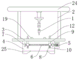
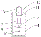
In order to achieve the above object, the utility model provides a following technical scheme: an engineering pipeline on-site punching anti-deviation structure comprises a punching machine, a placing plate and a workbench, wherein two supporting rods are fixedly mounted on two sides of the top of the placing plate, a middle rod is fixedly mounted at the tops of the two supporting rods, the punching machine is arranged in the middle of the bottom end of the middle rod, the workbench is hollow, a forward screw rod and a reverse screw rod are arranged in the workbench, limiting blocks are arranged at two ends of the forward screw rod and the reverse screw rod, one end of the forward screw rod extends towards the outside of the workbench and is connected to the output end of a servo motor in a penetrating manner, a communicating block is movably connected to the forward screw rod and the reverse screw rod through a threaded structure, a telescopic rod is fixed to the communicating block, an air cylinder is fixedly mounted at the bottom end of the communicating block, a fixed block is fixedly arranged at the upper end of the telescopic rod, and fixing rings are fixedly attached to two sides of the fixed block;
the movable block is clamped on the placing plate, a limiting plate is fixedly connected to the upper end of the movable block, the side face of the limiting plate is fixedly connected to one end of the tension spring, an arc-shaped clamping block is fixedly connected to the other end of the tension spring, a compression spring is fixedly connected to the upper end of the limiting plate, and the upper end of the compression spring is fixedly connected with a compression plate through a spring plate.
Preferably, the upper end face of the workbench is provided with a sliding chute, and the fixing ring penetrates through the sliding chute.
Preferably, solid fixed ring upper end is the arc structure, just gu fixed the laminating has the rubber pad on the fixed ring inside wall.
Preferably, the limiting plate is provided with an opening, the placing plate penetrates through the opening, and the distance between the two sides of the inner wall of the opening is equal to the distance between the two sides of the outer wall of the placing plate.
Preferably, the side surface of the compression plate is fixedly connected with a limiting rod, the other end of the limiting rod is connected with a limiting groove in a sliding mode, and the limiting groove is formed in the arc-shaped clamping block.
Preferably, the extension spring with compression spring all is provided with two, workstation bottom end four corners department is equipped with the base.
Compared with the prior art, the beneficial effects of the utility model are that: the utility model discloses place the engineering pipeline when using on placing the board, press from both sides the pipeline through the arc clamp splice and get, through the extension spring, the interact of compression spring and gag lever post, can make the pipeline more stable press from both sides by the arc clamp splice and get, and be applicable to the pipeline of equidimension not, the suitability has been improved, it rotates to drive the forward and reverse screw rod through servo motor, make the fixed block reverse or the syntropy motion in the spout, and then the position of length adjustment fixed block according to different tubular products, it is flexible to make the telescopic link through the cylinder, solid fixed ring lapse, be applicable to the pipeline of co-altitude, the realization is fixed to the pipeline, the reuse puncher punches to the pipeline.
Drawings
FIG. 1 is a schematic structural view of the present invention;
FIG. 2 is a schematic view of the fixing device of the present invention;
FIG. 3 is a schematic view of a partial structure of the fixing device of the present invention;
fig. 4 is a schematic view of the mounting structure of the moving block of the present invention;
fig. 5 is a schematic side view of the present invention.
In the figure: 1 puncher, 2 bracing pieces, 3 place boards, 4 workstations, 5 servo motors, 6 forward and reverse screws, 7 limiting blocks, 8 communicating blocks, 9 telescopic rods, 10 cylinders, 11 fixing blocks, 12 fixing rings, 13 rubber pads, 14 sliding chutes, 15 moving blocks, 16 openings, 17 limiting plates, 18 tension springs, 19 arc-shaped clamping blocks, 20 limiting grooves, 21 limiting rods, 22 compression springs, 23 compression plates, 24 middle rods and 25 bases.
Detailed Description
The technical solutions in the embodiments of the present invention will be described clearly and completely with reference to the accompanying drawings in the embodiments of the present invention, and it is obvious that the described embodiments are only some embodiments of the present invention, not all embodiments. Based on the embodiments in the present invention, all other embodiments obtained by a person skilled in the art without creative work belong to the protection scope of the present invention.
In the description of the present invention, it should be understood that the terms "upper", "lower", "top", "bottom", "inner", "outer", "front", "rear", "left", "right", and the like indicate orientations or positional relationships based on the orientations or positional relationships shown in fig. 1, and are only for convenience of description and simplification of description, but do not indicate or imply that a device or structure to be referred to must have a specific orientation, be constructed in a specific orientation, and be operated, and therefore should not be construed as limiting the present invention.
Referring to fig. 1-5, the present invention provides a technical solution: an engineering pipeline on-site punching anti-deviation structure comprises a punching machine 1, a placing plate 3 and a workbench 4, wherein two supporting rods 2 are fixedly mounted on two sides of the top of the placing plate 3, a middle rod 24 is fixedly mounted on the tops of the two supporting rods 2, the punching machine 1 is arranged in the middle of the bottom end of the middle rod 24, the workbench 4 is hollow, a forward screw 6 and a reverse screw 6 are arranged in the workbench, two ends of the forward screw 6 and the reverse screw 6 are provided with limit blocks 7, one end of each forward screw extends towards the outside of the workbench 4 and is connected with the output end of a servo motor 5 in a penetrating manner, a communicating block 8 is movably connected onto the forward screw 6 through a threaded structure, a telescopic rod 9 is fixed onto the communicating block 8, an air cylinder 10 is fixedly mounted at the bottom end of the communicating block 8, a fixed block 11 is fixedly arranged at the upper end of the telescopic rod 9, and fixing rings 12 are fixedly attached to two sides of the fixed block 11;
place the board 3 and go up the joint and have the movable block 15, the rigid coupling of movable block 15 upper end has limiting plate 17, limiting plate 17 side rigid coupling in the one end of extension spring 18, and the other end rigid coupling of extension spring 18 has arc clamp splice 19, and limiting plate 17 upper end rigid coupling has compression spring 22, and compression spring 22 upper end is through spring board fixedly connected with compression plate 23.
The upper end surface of the working table 4 is provided with a sliding chute 14, and the fixing ring 12 penetrates through the sliding chute 14.
The upper end of the fixing ring 12 is of an arc-shaped structure, and a rubber pad 13 is fixedly attached to the inner side wall of the fixing ring 12.
Limiting plate 17 is provided with opening 16, and place board 3 and run through opening 16, and opening 16 inner wall both sides distance is the same with place board 3 outer wall both sides distance.
The compression plate 23 side fixedly connected with gag lever post 21, gag lever post 21 other end sliding connection in spacing groove 20, and spacing groove 20 is seted up in arc clamp splice 19.
The number of the tension springs 18 and the number of the compression springs 22 are two, and the four corners of the bottom end of the workbench 4 are provided with bases 25.
The working principle is as follows: the utility model discloses place the engineering pipeline when using on placing board 3, press from both sides the pipeline through arc clamp splice 19 and get, through extension spring 18, compression spring 22 and gag lever post 21 interact, can make the pipeline more stable get by arc clamp splice 19 clamp and get, and be applicable to the pipeline of equidimension not, the suitability has been improved, drive forward and reverse screw rod 6 through servo motor 5 and rotate, make fixed block 11 reverse or the syntropy motion in spout 14, and then the position according to the length adjustment fixed block of different tubular products, it is flexible to make telescopic link 9 through cylinder 10, solid fixed ring 12 slides down, be applicable to the pipeline of co-altitude not, the realization is fixed to the pipeline, reuse puncher 1 punches to the pipeline.
Although embodiments of the present invention have been shown and described, it will be appreciated by those skilled in the art that changes, modifications, substitutions and alterations can be made in these embodiments without departing from the principles and spirit of the invention, the scope of which is defined in the appended claims and their equivalents.
Claims (6)
1. The utility model provides an engineering pipeline on-spot anti-shifting structure that punches, includes puncher (1), places board (3) and workstation (4), its characterized in that: two supporting rods (2) are fixedly arranged on two sides of the top of the placing plate (3), a middle rod (24) is fixedly arranged on the top of the two supporting rods (2), the middle part of the bottom end of the middle rod (24) is provided with a perforating machine (1), the workbench (4) is hollow, a forward and reverse screw rod (6) is arranged in the inner part of the screw rod, two ends of the forward and reverse screw rod (6) are provided with limit blocks (7), one end of the air inlet pipe extends to the outside of the workbench (4) and is connected with the output end of the servo motor (5) in a penetrating way, the forward and reverse screw rods (6) are movably connected with a communicating block (8) through a thread structure, a telescopic rod (9) is fixed on the communicating block (8), an air cylinder (10) is fixedly arranged at the bottom end of the communicating block (8), a fixed block (11) is fixedly arranged at the upper end of the telescopic rod (9), and fixed rings (12) are fixedly attached to two sides of the fixed block (11);
the clamping device is characterized in that a moving block (15) is clamped on the placing plate (3), a limiting plate (17) is fixedly connected to the upper end of the moving block (15), the side of the limiting plate (17) is fixedly connected to one end of a tension spring (18), an arc-shaped clamping block (19) is fixedly connected to the other end of the tension spring (18), a compression spring (22) is fixedly connected to the upper end of the limiting plate (17), and a compression plate (23) is fixedly connected to the upper end of the compression spring (22).
2. The on-site punching anti-deviation structure of the engineering pipeline according to claim 1, wherein: the upper end face of the workbench (4) is provided with a sliding chute (14), and the fixing ring (12) penetrates through the sliding chute (14).
3. The on-site punching anti-deviation structure of the engineering pipeline according to claim 1, wherein: the upper end of the fixing ring (12) is of an arc-shaped structure, and a rubber pad (13) is fixedly attached to the inner side wall of the fixing ring (12).
4. The on-site punching anti-deviation structure of the engineering pipeline according to claim 1, wherein: an opening (16) is formed in the limiting plate (17), the placing plate (3) penetrates through the opening (16), and the distance between the two sides of the inner wall of the opening (16) is the same as the distance between the two sides of the outer wall of the placing plate (3).
5. The on-site punching anti-deviation structure of the engineering pipeline according to claim 1, wherein: compression plate (23) side fixedly connected with gag lever post (21), gag lever post (21) other end sliding connection is in spacing groove (20), spacing groove (20) are seted up in arc clamp splice (19).
6. The on-site punching anti-deviation structure of the engineering pipeline according to claim 1, wherein: extension spring (18) with compression spring (22) all are provided with two, workstation (4) bottom four corners department is equipped with base (25).
Priority Applications (1)
| Application Number | Priority Date | Filing Date | Title |
|---|---|---|---|
| CN202023241375.7U CN214264015U (en) | 2020-12-29 | 2020-12-29 | On-spot anti-shifting structure that punches of engineering pipeline |
Applications Claiming Priority (1)
| Application Number | Priority Date | Filing Date | Title |
|---|---|---|---|
| CN202023241375.7U CN214264015U (en) | 2020-12-29 | 2020-12-29 | On-spot anti-shifting structure that punches of engineering pipeline |
Publications (1)
| Publication Number | Publication Date |
|---|---|
| CN214264015U true CN214264015U (en) | 2021-09-24 |
Family
ID=77784130
Family Applications (1)
| Application Number | Title | Priority Date | Filing Date |
|---|---|---|---|
| CN202023241375.7U Active CN214264015U (en) | 2020-12-29 | 2020-12-29 | On-spot anti-shifting structure that punches of engineering pipeline |
Country Status (1)
| Country | Link |
|---|---|
| CN (1) | CN214264015U (en) |
-
2020
- 2020-12-29 CN CN202023241375.7U patent/CN214264015U/en active Active
Similar Documents
| Publication | Publication Date | Title |
|---|---|---|
| CN210452770U (en) | Automatic clamping device | |
| CN214264015U (en) | On-spot anti-shifting structure that punches of engineering pipeline | |
| CN211465420U (en) | Multifunctional automatic screw locking machine | |
| CN219254595U (en) | Door frame welding positioning tool | |
| CN216138534U (en) | Machining positioning fixture | |
| CN218340753U (en) | Special punch device for pipe machining | |
| CN214518862U (en) | Generator end cover machining tool based on five-axis machining center | |
| CN211639138U (en) | Clamp for drilling center hole of square workpiece | |
| CN212946602U (en) | Rapid fixing clamp | |
| CN210099821U (en) | Multi-shaft transmission clamp device | |
| CN211564683U (en) | Hydraulic combined punching and shearing machine | |
| CN208437465U (en) | A kind of agricultural machinery sheet metal component punching press, welded formula device | |
| CN219665266U (en) | Plate fixing device of mechanical plate shearing machine | |
| CN213356152U (en) | Section bar processing material overturning and conveying device | |
| CN220463029U (en) | H-shaped steel cutting device | |
| CN213591830U (en) | Fixing clamp for processing iron sheet | |
| CN220480313U (en) | High-precision mechanical part punching device | |
| CN218050147U (en) | Forging press clamping device with protective structure | |
| CN220050949U (en) | Clamping tool for machining cylindrical parts | |
| CN215548483U (en) | Mobile platform suitable for processing of semiconductor equipment parts | |
| CN219766526U (en) | Multifunctional movable combined punching machine | |
| CN216706509U (en) | Tool clamp for welding L-shaped section bar and square section bar | |
| CN219504207U (en) | Multi-station numerical control drilling device with good clamping effect | |
| CN219130433U (en) | Metal tube bending device | |
| CN210281215U (en) | Tool positioning device for robot welding |
Legal Events
| Date | Code | Title | Description |
|---|---|---|---|
| GR01 | Patent grant | ||
| GR01 | Patent grant |