CN214250916U - Shaft part measuring device with center hole as axis reference - Google Patents
Shaft part measuring device with center hole as axis reference Download PDFInfo
- Publication number
- CN214250916U CN214250916U CN202120385011.1U CN202120385011U CN214250916U CN 214250916 U CN214250916 U CN 214250916U CN 202120385011 U CN202120385011 U CN 202120385011U CN 214250916 U CN214250916 U CN 214250916U
- Authority
- CN
- China
- Prior art keywords
- driving wheel
- workpiece
- clamping block
- measuring
- measuring device
- Prior art date
- Legal status (The legal status is an assumption and is not a legal conclusion. Google has not performed a legal analysis and makes no representation as to the accuracy of the status listed.)
- Active
Links
Images


Landscapes
- A Measuring Device Byusing Mechanical Method (AREA)
Abstract
The utility model discloses a shaft part measuring device taking a central hole as an axis datum, which comprises a clamping component, a driving component and a measuring component, wherein the clamping component fixes a workpiece through a Morse taper tip; the driving assembly comprises a motor, a driving wheel, a cylinder and a tension spring, the motor drives the driving wheel to rotate, the driving wheel is connected to the cylinder, the driving wheel is in contact with a workpiece, the tension spring is connected with the driving wheel, and the extension direction of the tension spring is the same as the horizontal movement direction of the driving wheel; the measuring assembly comprises a radial fitting sensor and a measuring sensor, the radial fitting sensor and the driving wheel synchronously move horizontally, and a measuring surface of the measuring sensor is aligned with the workpiece. By the mode, the utility model can adapt to batch measurement of shaft parts, and has accurate repeated positioning and high efficiency; the radial displacement generated in the rotating process of the workpiece is corrected through real-time automatic fitting of the radial fitting sensor, the measuring precision of the shaft parts is improved, and the influence of the self precision error of a measuring system on the measuring result is effectively avoided.
Description
Technical Field
The utility model relates to a beat and measure technical field, especially relate to an use axle type part measuring device of centre bore as axis benchmark.
Background
Due to the structural characteristics of the shafting parts, the central hole is the most important technological means in the shafting part processing as the reference. According to the process control requirement, for high-precision shafting parts, as the key parts for connection and transmission are borne in the equipment, the form and position tolerance of the shafting parts must be strictly controlled, otherwise, the final assembly precision cannot be ensured, and the use requirement of the whole mechanism is met.
At present, the production and processing problems of the processing of high-precision shaft parts are basically solved along with the use of a large number of precise CNC machine tools and processing centers, but the detection of the high-precision shaft parts still is a technical problem troubling related enterprises. The traditional detection method for measuring items such as run-out and the like of high-precision shaft parts by taking a center hole as an axis reference in the industry at present comprises the following steps:
1. the three-coordinate measuring instrument is used for measuring the jumping between the reference surface of the center hole of the product and the excircle of the measured part, and the measuring precision is high.
2. And (3) positioning the workpiece by using the fixed center through the center hole, manually rotating the workpiece, and checking the jump of the machined surface by using a dial indicator.
3. The centers at two ends are internally provided with rolling bearings to position the workpiece by a central hole, the centers and the workpiece rotate together, and a measuring sensor is used for automatic measurement.
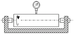
The measuring principle of geometric tolerance such as run-out of shaft parts by taking a center hole as a reference is shown in figure 1. The traditional high-precision shaft part measuring method has the following defects:
1. the use of a three-coordinate measuring machine, although highly accurate, is extremely inefficient.
2. The fixed center is adopted for manual measurement, the measurement mode is simple in structure and low in manufacturing cost, but cannot meet the automatic measurement requirement of equipment, can only be used as sampling inspection during batch production, and cannot be used for online real-time batch detection.
3. The positioning mode that rolling bearings are arranged inside the centers at the two ends can meet the requirement of rapid and efficient measurement. However, the rigidity of the movable thimble is poor, and a rotation gap is generated due to a bearing gap, so that the measurement precision and repeatability requirements cannot be met in occasions with high coaxiality and jumping requirements.
SUMMERY OF THE UTILITY MODEL
The utility model discloses the main technical problem who solves provides an use the centre bore as axle type part measuring device of axis benchmark, can improve the measurement accuracy of axle type part, can effectively avoid measurement system self precision error to measuring result's influence.
In order to achieve the above object, the technical solution of the present invention is:
a shaft part measuring device taking a center hole as an axis datum comprises:
the clamping assembly fixes the workpiece through a Morse taper tip;
the driving assembly comprises a motor, a driving wheel, a cylinder and a tension spring, the motor drives the driving wheel to rotate, the driving wheel is connected to the cylinder, the driving wheel is in contact with a workpiece, the tension spring is connected with the driving wheel, and the extension direction of the tension spring is the same as the horizontal moving direction of the driving wheel;
the measuring assembly comprises a radial fitting sensor and a measuring sensor, the radial fitting sensor and the driving wheel synchronously move horizontally, and a measuring surface of the measuring sensor is aligned with the workpiece.
Preferably, the support device further comprises a support assembly, the support assembly comprises a base and a sliding table, a sliding rail is arranged on the base, the sliding table is arranged on the sliding rail, and the sliding table is connected with the base in a sliding manner; the driving wheel is arranged on the sliding table.
Preferably, one end of the tension spring, which is close to the workpiece, is fixed on the base, and one end of the tension spring, which is far away from the workpiece, is connected to the sliding table.
Preferably, the radial fitting sensor is arranged on the sliding table.
Preferably, the clamping assembly comprises an upper clamping block, a lower clamping block and a connecting plate, the upper clamping block and the lower clamping block are arranged on the connecting plate, the upper clamping block is arranged above the lower clamping block, and a workpiece is positioned between the upper clamping block and the lower clamping block.
Preferably, the upper clamping block and the lower clamping block both comprise a morse taper tip, a tip sleeve and a tip block, the tip sleeve is sleeved on the morse taper tip, the tip sleeve is connected to the tip block, and the tip block is connected to the connecting plate.
Preferably, the clamping assembly further comprises a sliding block, a sliding groove is formed in the connecting plate, the sliding block is arranged on the sliding groove of the connecting plate, the sliding block is connected with the connecting plate in a sliding mode, and the upper clamping block is arranged on the sliding block.
Preferably, the driving assembly further comprises a synchronous belt, and the driving wheel is connected with the motor through the synchronous belt.
Preferably, the radial fit sensor is a displacement sensor.
Because of above-mentioned technical scheme's application, compared with the prior art, the utility model has the following beneficial effect:
the shaft part measuring device with the center hole as the axis reference is provided, the center hole of the center positioning workpiece in Morse taper fit is used as the mechanical reference, repeated positioning is accurate, efficiency is high, and the shaft part measuring device can adapt to batch measurement of shaft parts; the radial displacement generated in the rotating process of the workpiece is corrected through real-time automatic fitting of the radial fitting sensor, the measurement precision of the shaft parts is improved, the influence of the self precision error of a measurement system on the measurement result can be effectively avoided, and the requirement on the measurement precision of the workpiece can be met.
Drawings
Fig. 1 is a schematic diagram of geometric tolerance measurement of a shaft part based on a central hole.
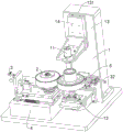
Fig. 2 is a schematic structural diagram of the shaft part measuring device using the center hole as the axis reference.
Fig. 3 is a cross-sectional view of the clamping assembly in the shaft part measuring device using the center hole as the axis reference.
Fig. 4 is a schematic structural diagram of a driving assembly and a measuring assembly in the shaft part measuring device using the central hole as the axis reference of the present invention.
Description of reference numerals:
the clamping device comprises a clamping component 1, an upper clamping block 11, a Morse taper tip 111, a tip sleeve 112, a tip block 113, a lower clamping block 12, a connecting plate 13, a sliding groove 131 and a sliding block 14;
the device comprises a driving component 2, a motor 21, a driving wheel 22, an air cylinder 23, a tension spring 24 and a synchronous belt 25;
a measuring assembly 3, a radial fitting sensor 31, a measuring sensor 32;
the supporting component 4, the base 41, the sliding rail 411 and the sliding table 42;
a workpiece 5.
Detailed Description
The following detailed description of the preferred embodiments of the present invention will be provided in conjunction with the accompanying drawings, so as to enable those skilled in the art to more easily understand the advantages and features of the present invention, and thereby define the scope of the invention more clearly and clearly.
Referring to the drawings, a shaft part measuring device taking a center hole as an axis datum comprises: clamping assembly 1, drive assembly 2 and measuring assembly 3. The measuring device further comprises a support assembly 4, and the support assembly 4 comprises a base 41 and a sliding table 42. The base 41 is blackened by common steel materials, and provides an installation foundation for the whole device. The base 41 is provided with a slide rail 411, the sliding table 42 is arranged on the slide rail 411, and the sliding table 42 is connected with the base 41 in a sliding manner. The drive wheel 22 is provided on the slide table 42.
The clamping assembly 1 is used for firmly clamping and positioning the workpiece 5 to be measured so as to reduce measurement errors caused by positioning and ensure the measurement accuracy and repeatability. The clamping component 1 fixes the workpiece 5 through the Morse taper tip 111, and the Morse taper tip 111 can be a conventional Morse taper tip 111 in the prior art.
The clamping assembly 1 comprises an upper clamping block 11, a lower clamping block 12 and a connecting plate 13, the upper clamping block 11 and the lower clamping block 12 are arranged on the connecting plate 13, the upper clamping block 11 is arranged above the lower clamping block 12, and the workpiece 5 is positioned between the upper clamping block 11 and the lower clamping block 12. The upper clamping block 11 and the lower clamping block 12 both comprise a Morse taper tip 111, a tip sleeve 112 and a tip block 113, the tip sleeve 112 is sleeved on the Morse taper tip 111, the tip sleeve 112 is connected on the tip block 113, and the tip block 113 is connected on the connecting plate 13.
For example, the clamping assembly 1 is suitable for workpieces 5 with different heights, and further comprises a sliding block 14, wherein the connecting plate 13 is provided with a sliding groove 131, the sliding block 14 is arranged on the sliding groove 131 of the connecting plate 13, the sliding block 14 is connected with the connecting plate 13 in a sliding mode, and the upper clamping block 11 is arranged on the sliding block 14. The position of the upper clamping block 11 can be changed by moving the slide 14 so as to clamp and fix different workpieces 5.
When the workpiece 5 is loaded, the workpiece 5 to be measured is supported on the lower clamping block 12 through a central hole, the upper clamping block 11 can move in a manual mode or a mode of being driven by the air cylinder 23, and the upper clamping block 11 is moved to the central hole of the workpiece 5. The workpiece 5 is automatically guided and clamped through the positioning of the central hole, and the workpiece 5 to be detected is firmly clamped on the clamping assembly 1 under the action of the Morse taper tip 111.
The driving assembly 2 comprises a motor 21, a driving wheel 22, a cylinder 23 and a tension spring 24, wherein the motor 21 drives the driving wheel 22 to rotate, so that the workpiece 5 is driven to rotate to realize automatic dynamic measurement. In order to better perform the driving function, the driving assembly 2 further comprises a timing belt 25, and the driving wheel 22 is connected with the motor 21 through the timing belt 25. The driving wheel 22 is connected to the cylinder 23, and the driving wheel 22 contacts with the workpiece 5, and the workpiece 5 is driven to rotate by the driving wheel 22. A gear may be provided on the outer surface of the drive wheel 22 such that the drive wheel 22 is in meshing engagement with the workpiece 5.
The tension spring 24 is connected with the driving wheel 22, one end of the tension spring 24 close to the workpiece 5 is fixed on the base 41, one end of the tension spring 24 far away from the workpiece 5 is connected on the sliding table 42, and the stretching direction of the tension spring 24 is the same as the horizontal moving direction of the driving wheel 22. The driving wheel 22 realizes axial feeding under the acting force of the cylinder 23, and the driving wheel 22 and the workpiece 5 to be measured are always kept in close fit through the acting force of the tension spring 24, so that the precision is high and the sliding property is good.
The measuring assembly 3 comprises a radial fitting sensor 31 and a measuring sensor 32, the radial fitting sensor 31 moving horizontally in synchronism with the driving wheel 22. The radial fitting sensor 31 can be fixedly arranged on the sliding table 42 through a bracket, the radial fitting sensor 31 is a displacement sensor, and the radial fitting sensor 31 measures the movement amount of the sliding table 42 to measure the radial change of the workpiece 5. During the rotation measurement of the workpiece 5, the displacement of the driving coil is moved by the amount of the radial displacement of the driving wheel 22 during the rotation to generate a variation, and the measurement value of the sensor radial fitting reference is detected.
The measuring sensor 32 is located on one side of the workpiece 5, the measuring surface of the measuring sensor 32 is aligned with the workpiece 5, and different measuring sensors 32 can be selected according to the content to be measured, so that different measuring objects can be measured.
Taking gear shaft runout measurement as an example, in the actual measurement process, when a workpiece 5 is fed, the workpiece 5 is clamped by adopting the Morse taper center 111, the accuracy of the center is high because the upper clamping block 11 and the lower clamping block 12 adopt the center matched with the Morse taper, the upper center and the lower center can be matched with the central hole of the workpiece 5 without gaps, the runout of the center can reach 0.001mm, the accurate positioning of the central hole of the workpiece 5 is taken as the mechanical reference of the whole measurement mechanism, and the repeated positioning accuracy guarantee is effectively provided for the whole measurement mechanism.
The driving wheel 22 is moved to the workpiece 5 to be closely attached by using the cylinder 23 as a driving carrier through the slide rail 411 and the slide table 42 on the base 41. In the initial state, the tension spring 24 is in a naturally relaxed state, and when the drive wheel 22 moves in a direction to approach the workpiece 5, the tension spring 24 is stretched.
Under the traction action of the restoring force of the tension spring 24, the driving wheel 22 and the workpiece 5 to be measured can be always in close fit, and the motor 21 is used for driving the driving wheel 22 to drive the workpiece 5 to rotate, so that automatic dynamic measurement is realized. In the whole dynamic measurement process, the radial fitting sensor 31 arranged in the radial direction moves through the radial displacement in the rotation process of the workpiece 5 to drive the displacement of the coil to generate variation, the measurement value of the radial fitting reference of the sensor is detected, the radial displacement generated in the rotation process of the workpiece 5 is automatically fitted and corrected in real time, the beating form and position tolerance parameters of the shaft part are obtained according to the mechanical reference and the sensor fitting reference, and the beating measurement of the gear shaft is completed.
It should be noted that, the measuring device may be arranged with a plurality of sets of measuring sensors 32 as required, and is used for measuring other measuring elements of the shaft-like part. All measurement requirements of the whole shaft part are met through one set of measuring device, the whole measuring device is integrated and has higher integration level, and the measuring device can be widely applied to an automatic production line, meets the requirements of modernization and automatic development of the whole industry, and is not described one by one.
The above is only the embodiment of the present invention, not limiting the scope of the present invention, all the equivalent structures or equivalent processes of the present invention are used in the specification and the attached drawings, or directly or indirectly applied to other related technical fields, and all the same principles are included in the protection scope of the present invention.
Claims (9)
1. The utility model provides an use axle type part measuring device of centre bore as axis benchmark which characterized in that includes:
the clamping assembly fixes the workpiece through a Morse taper tip;
the driving assembly comprises a motor, a driving wheel, a cylinder and a tension spring, the motor drives the driving wheel to rotate, the driving wheel is connected to the cylinder, the driving wheel is in contact with a workpiece, the tension spring is connected with the driving wheel, and the extension direction of the tension spring is the same as the horizontal moving direction of the driving wheel;
the measuring assembly comprises a radial fitting sensor and a measuring sensor, the radial fitting sensor and the driving wheel synchronously move horizontally, and a measuring surface of the measuring sensor is aligned with the workpiece.
2. The shaft part measuring device with the center hole as the axis reference as claimed in claim 1, wherein: the support assembly comprises a base and a sliding table, the base is provided with a sliding rail, the sliding table is arranged on the sliding rail, and the sliding table is connected with the base in a sliding manner; the driving wheel is arranged on the sliding table.
3. The shaft part measuring device with the center hole as the axis reference as claimed in claim 2, wherein: one end of the tension spring, which is close to the workpiece, is fixed on the base, and one end of the tension spring, which is far away from the workpiece, is connected to the sliding table.
4. The shaft part measuring device with the center hole as the axis reference as claimed in claim 2, wherein: the radial fitting sensor is arranged on the sliding table.
5. The shaft part measuring device with the center hole as the axis reference as claimed in claim 1, wherein: the clamping assembly comprises an upper clamping block, a lower clamping block and a connecting plate, the upper clamping block and the lower clamping block are arranged on the connecting plate, the upper clamping block is arranged above the lower clamping block, and a workpiece is located between the upper clamping block and the lower clamping block.
6. The shaft part measuring device with the center hole as the axis reference as claimed in claim 5, wherein: the upper clamping block and the lower clamping block respectively comprise a Morse taper tip, a tip sleeve and a tip block, the tip sleeve is sleeved on the Morse taper tip, the tip sleeve is connected to the tip block, and the tip block is connected to the connecting plate.
7. The shaft part measuring device with the center hole as the axis reference as claimed in claim 5, wherein: the clamping assembly further comprises a sliding block, a sliding groove is formed in the connecting plate, the sliding block is arranged on the sliding groove of the connecting plate and is connected with the connecting plate in a sliding mode, and the upper clamping block is arranged on the sliding block.
8. The shaft part measuring device with the center hole as the axis reference as claimed in claim 1, wherein: the driving assembly further comprises a synchronous belt, and the driving wheel is connected with the motor through the synchronous belt.
9. The shaft part measuring device with the center hole as the axis reference as claimed in claim 1, wherein: the radial fitting sensor is a displacement sensor.
Priority Applications (1)
| Application Number | Priority Date | Filing Date | Title |
|---|---|---|---|
| CN202120385011.1U CN214250916U (en) | 2021-02-20 | 2021-02-20 | Shaft part measuring device with center hole as axis reference |
Applications Claiming Priority (1)
| Application Number | Priority Date | Filing Date | Title |
|---|---|---|---|
| CN202120385011.1U CN214250916U (en) | 2021-02-20 | 2021-02-20 | Shaft part measuring device with center hole as axis reference |
Publications (1)
| Publication Number | Publication Date |
|---|---|
| CN214250916U true CN214250916U (en) | 2021-09-21 |
Family
ID=77726946
Family Applications (1)
| Application Number | Title | Priority Date | Filing Date |
|---|---|---|---|
| CN202120385011.1U Active CN214250916U (en) | 2021-02-20 | 2021-02-20 | Shaft part measuring device with center hole as axis reference |
Country Status (1)
| Country | Link |
|---|---|
| CN (1) | CN214250916U (en) |
Cited By (2)
| Publication number | Priority date | Publication date | Assignee | Title |
|---|---|---|---|---|
| CN113945155A (en) * | 2021-10-14 | 2022-01-18 | 上海羿弓精密科技有限公司 | High-precision RV reducer crankshaft detection device |
| CN114279328A (en) * | 2021-12-24 | 2022-04-05 | 上海羿弓精密科技有限公司 | Special measuring equipment of ultrahigh-precision RV reducer crankshaft |
-
2021
- 2021-02-20 CN CN202120385011.1U patent/CN214250916U/en active Active
Cited By (4)
| Publication number | Priority date | Publication date | Assignee | Title |
|---|---|---|---|---|
| CN113945155A (en) * | 2021-10-14 | 2022-01-18 | 上海羿弓精密科技有限公司 | High-precision RV reducer crankshaft detection device |
| CN113945155B (en) * | 2021-10-14 | 2022-10-25 | 上海羿弓精密科技有限公司 | High-precision RV reducer crankshaft detection device |
| CN114279328A (en) * | 2021-12-24 | 2022-04-05 | 上海羿弓精密科技有限公司 | Special measuring equipment of ultrahigh-precision RV reducer crankshaft |
| CN114279328B (en) * | 2021-12-24 | 2022-12-27 | 上海羿弓精密科技有限公司 | Special measuring equipment of ultrahigh precision RV reduction gear bent axle |
Similar Documents
| Publication | Publication Date | Title |
|---|---|---|
| CN107514965B (en) | Crankshaft main journal roundness and crankshaft coaxiality error detection device | |
| CN102944472B (en) | Device and method for measuring axial static rigidity of ball screw pair | |
| CN105865340B (en) | Rolling linear guide precision self-operated measuring unit and method | |
| CN214250916U (en) | Shaft part measuring device with center hole as axis reference | |
| CN107314731B (en) | Detection tool for detecting center difference of outer star wheel of ball cage and detection method using detection tool | |
| CN110160454A (en) | A kind of bearing assembly clearance on-line measurement machine and its clearance measurement method | |
| CN113280709A (en) | Driving device for measuring runout of shaft parts without center holes | |
| CN110455247B (en) | Gear clamp suitable for roughness profiler | |
| CN106370140A (en) | Locating device for measuring tubular parts | |
| CN106705791B (en) | Outer circle jumping detection tool for generator rotor | |
| CN210625623U (en) | Novel parallelism detector | |
| CN109238066A (en) | A kind of measurement method of Large Crankshaft end face run-out | |
| CN207991440U (en) | Concentricity detecting tool | |
| CN217179548U (en) | Online measuring equipment for excircle of part | |
| CN110702006A (en) | Device for automatically detecting position precision of peripheral cloth holes | |
| CN113945155B (en) | High-precision RV reducer crankshaft detection device | |
| CN111766063B (en) | Automatic detector for protruding amount of angular contact ball bearing | |
| CN206601246U (en) | A kind of test platform for studying single shaft resetting error mechanism | |
| CN210665059U (en) | Automatic measuring and clamping workbench for slewing bearing | |
| CN114777706A (en) | High-precision measuring device for rotation precision of double-row cylindrical roller bearing | |
| CN212321074U (en) | Automatic detection machine for protrusion amount of angular contact ball bearing | |
| CN210374944U (en) | Eccentric shaft measuring instrument | |
| CN110686585B (en) | Assembly method for inhibiting repeated positioning errors of linear shaft of precision machine tool | |
| KR102670183B1 (en) | Supporting jig device for precise measurement of spindle | |
| CN220708359U (en) | Form and position tolerance detection equipment of shafting assembly body |
Legal Events
| Date | Code | Title | Description |
|---|---|---|---|
| GR01 | Patent grant | ||
| GR01 | Patent grant |