CN214243833U - Flow stabilizing box for hydraulic screen - Google Patents
Flow stabilizing box for hydraulic screen Download PDFInfo
- Publication number
- CN214243833U CN214243833U CN202022825614.7U CN202022825614U CN214243833U CN 214243833 U CN214243833 U CN 214243833U CN 202022825614 U CN202022825614 U CN 202022825614U CN 214243833 U CN214243833 U CN 214243833U
- Authority
- CN
- China
- Prior art keywords
- flow
- box
- flow stabilizing
- stabilizing box
- screen
- Prior art date
- Legal status (The legal status is an assumption and is not a legal conclusion. Google has not performed a legal analysis and makes no representation as to the accuracy of the status listed.)
- Active
Links
Images


Abstract
The utility model relates to a steady flow box for a hydraulic screen, which comprises a steady flow box body and a steady flow baffle plate, wherein the steady flow box body is provided with a steady flow box water inlet and a steady flow box water outlet; the flow stabilizing partition plate is fixedly arranged inside the flow stabilizing box body, and the flow stabilizing partition plate completely covers the water inlet of the flow stabilizing box along the projection in the direction vertical to the water inlet of the flow stabilizing box. The utility model discloses when using, no matter what kind of speed of rivers flows in from the stationary flow case water inlet, all can the direct contact stationary flow baffle, and the impact force of rivers all can be acted on the stationary flow baffle, when the liquid level in the stationary flow case risees gradually to the stationary flow case delivery port, and the gentle outflow of stationary flow case delivery port will be followed to water, has realized reducing the effect of water impact. No matter whether the specification model of the liquid conveying equipment and the hydraulic sieve connected with it matches, all can pass through the utility model discloses the intercommunication, and the problem that liquid splashes about can not appear has improved the interchangeability of current equipment, has practiced thrift the cost of enterprise.
Description
Technical Field
The utility model relates to a sewage treatment device technical field especially relates to a stationary flow case for hydraulic screen.
Background
Along with the development of science and technology, the urbanization process of China is accelerated, the city scale is larger and larger, and various problems are more and more accompanied. The treatment of urban sewage is a critical problem which has to be faced by the need for urban sanitation and hygiene.
The hydraulic screen (also called a hydraulic screen) is a device widely applied in the field of sewage treatment at present, can intercept suspended matters in liquid by adopting a porous material, has the characteristics of simplicity, high efficiency, convenient maintenance and the like, and is suitable for removing solid suspended impurities from low-concentration solution. Besides sewage treatment, the method is also commonly used for treating industrial wastewater such as printing and dyeing wastewater, poultry processing and the like. The hydraulic screen is divided into a fixed plane type hydraulic screen, a fixed curved surface type hydraulic screen, a hydraulic rotary screen and the like.
The hydraulic screen is typically used by a self-priming pump or other fluid delivery device to pump the fluid to be filtered into the hydraulic screen. However, in practical use, when the self-priming pump discharges water, the self-priming pump is not a smooth and stable water flow, but a water column with high speed and large impact force, if the water outlet of the self-priming pump is directly connected with the water inlet of the hydraulic screen, the discharged liquid also has large impact force and splashes around, and the discharged liquid is sprayed to a sewage treatment site to cause secondary pollution.
SUMMERY OF THE UTILITY MODEL
In view of the above, it is necessary to provide a flow stabilizing box for a hydraulic screen, so as to solve the problem of liquid splashing at the screen of the hydraulic screen connected to the flow stabilizing box due to the excessive water output power of a hydraulic pumping device such as a self-priming pump.
The utility model provides a stationary flow case for hydraulic screen, include:
the flow stabilizing box body is provided with a flow stabilizing box water inlet and a flow stabilizing box water outlet, the plurality of flow stabilizing box water outlets face to the same side of the flow stabilizing box body, and the axes of the plurality of flow stabilizing box water outlets are positioned in the same horizontal plane;
and the flow stabilizing partition board is fixedly arranged inside the flow stabilizing box body, completely covers the water inlet of the flow stabilizing box along the projection in the direction vertical to the water inlet of the flow stabilizing box, is a composite board and comprises a supporting layer and a buffer layer.
Optionally, the water inlet of the flow stabilizing box is located on the bottom plate of the flow stabilizing box, the water outlet of the flow stabilizing box is located on one side plate of the flow stabilizing box, and the water inlet of the flow stabilizing box and the water outlet of the flow stabilizing box are respectively located on two sides of the flow stabilizing partition plate.
Optionally, the supporting layer is the same as the material of the flow stabilizing box body, the buffer layer is made of waterproof rubber, and the buffer layer faces towards the water inlet of the flow stabilizing box body.
Optionally, a plurality of buffer slots are formed in one surface of the buffer layer, which deviates from the supporting layer.
Optionally, the flow stabilizing partition is a rectangular straight plate.
Optionally, one side of the flow stabilizing partition plate is fixedly connected to one side plate of the flow stabilizing box body, the extending direction of each buffer groove is perpendicular to the intersection line of the flow stabilizing partition plate and the side plate of the flow stabilizing box body, and the included angle between the flow stabilizing partition plate and the bottom plate of the box body is 15-75 degrees.
Optionally, the steady flow baffle is an arc-shaped plate, and the protruding direction of the arc-shaped plate deviates from the water inlet of the steady flow box.
Optionally, the flow stabilizing partition plate is formed by enclosing two straight edges and two arc-shaped edges, the two straight edges are parallel to each other, the shapes and the protruding directions of the two arc-shaped edges are the same, and the trend of each buffer groove is the same as that of the arc-shaped edge; one straight edge is fixedly connected with the bottom plate of the flow stabilizing box body.
The utility model provides a pair of a stationary flow case for hydraulic screen, no matter how fast rivers flow in from the stationary flow case water inlet, all can not directly flow from the stationary flow case water inlet, but direct contact stationary flow baffle, the impact force of rivers all can be used in the stationary flow baffle, the rivers convergence after having strikeed the stationary flow baffle is in the stationary flow box, when the liquid level in the stationary flow box risees gradually to the height of stationary flow case delivery port, the gentle outflow of stationary flow case delivery port will be followed to water in the stationary flow box, the effect of reducing the water impact has been realized. After the stationary flow case water inlet is connected like liquid conveying equipment such as self priming pump, stationary flow case delivery port connection hydraulic screen, no matter whether the specification model of liquid conveying equipment and hydraulic screen matches, all can pass through the utility model discloses the intercommunication, and the problem that liquid splashes about can not appear has improved the interchangeability of current equipment, has practiced thrift the cost of enterprise.
Drawings
FIG. 1 is a schematic structural view of a first embodiment of the anti-clogging rapid sewage treatment vehicle provided by the present invention;
FIG. 2 is a schematic structural view of the anti-clogging rapid sewage treatment vehicle provided by the present invention with the outer casing omitted;
FIG. 3 is a top view of the clean water tank of FIG. 2, but omitted;
FIG. 4 is a side sectional view of a grille machine in a first embodiment of the anti-clogging rapid sewage treatment vehicle provided by the present invention;
FIG. 5 is a cross-sectional view taken along line A-A of FIG. 4;
FIG. 6 is a schematic view of a screen of a grille machine according to an embodiment of the anti-clogging rapid sewage treatment vehicle of the present invention;
FIG. 7 is a front view of a grille machine in a first embodiment of the anti-clogging rapid sewage treatment vehicle provided by the present invention;
FIG. 8 is a rear view of a grille machine in a first embodiment of the anti-clogging rapid sewage treatment vehicle provided by the present invention;
FIG. 9 is a front view of a hydraulic screen in a first embodiment of the anti-clogging rapid sewage treatment vehicle provided by the present invention;
FIG. 10 is a top view of a hydraulic screen in a first embodiment of the anti-clogging rapid sewage treatment vehicle provided by the present invention;
FIG. 11 is a sectional view of an opened portion of a water collection tank of a first embodiment of the anti-clogging rapid sewage treatment vehicle of the present invention;
FIG. 12 is a side view of a hydraulic screen in a first embodiment of the anti-clogging rapid sewage treatment vehicle provided by the present invention;
FIG. 13 is a cross-sectional view taken along line B-B of FIG. 9;
FIG. 14 is an enlarged view of a portion of FIG. 13 at C;
FIG. 15 is a side sectional view of a steady flow box in a first embodiment of the anti-clogging rapid sewage treatment vehicle provided by the present invention;
FIG. 16 is a schematic structural view of a flow stabilizing partition plate in a first embodiment of the anti-clogging rapid sewage treatment vehicle provided by the present invention;
FIG. 17 is a front view of a steady flow box in a first embodiment of the anti-clogging rapid sewage treatment vehicle provided by the present invention;
fig. 18 is a side sectional view of a steady flow box in the second embodiment of the anti-clogging rapid sewage treatment vehicle provided by the present invention.
Detailed Description
The following detailed description of the preferred embodiments of the invention, which is to be read in connection with the accompanying drawings, forms a part of this application, and together with the embodiments of the invention, serve to explain the principles of the invention and not to limit its scope.
Example one
Combine fig. 1 ~ 3 to show, the utility model provides a pair of prevent blockking up sewage rapid treatment car, including automobile body 1, grid machine 2, hydraulic screen 3, vacuum pump 4, liquid delivery pump 5, power takeoff 6, power takeoff generator 7 and outer casing box 8, wherein automobile body 1 is the current commercial vehicle of purchase, and reequip its chassis, with outer casing box 8 fixed mounting on automobile body 1's chassis, grid machine 2, hydraulic screen 3, vacuum pump 4, liquid delivery pump 5, power takeoff generator 7 all are located outer casing box 8 and equal fixed mounting on automobile body 1's chassis. The vacuum pump 4 is a PNK MR roots vacuum pump in the embodiment, the liquid transfer pump 5 is a ZW type non-clogging sewage drainage self-priming pump in the embodiment, the power takeoff 6 is a French power takeoff 6, the grating machine 2 and the hydraulic screen 3 are self-made equipment, and the vacuum pump 4, the liquid grating machine 2, the liquid transfer pump 5 and the hydraulic screen 3 are sequentially communicated through pipelines (not shown in the figure). The power takeoff 6 is fixedly installed below a chassis of the vehicle body 1 and is in transmission connection with an engine main shaft of the vehicle body 1, the power takeoff generator 7 is fixedly installed above the chassis of the vehicle body 1, the power takeoff 6 is in transmission connection with the power takeoff generator 7, the power takeoff generator 7 is electrically connected with the grille machine 2, the hydraulic screen 3, the vacuum pump 4 and the liquid conveying pump 5, and the power takeoff generator 7 obtains power of the engine of the vehicle body 1 through the power takeoff 6 and provides electric energy for equipment connected with the power takeoff generator. The utility model discloses earlier when using connect a charge-in pipeline with grid machine 2 and stretch into the sewage pond that needs were handled, take out to the negative pressure in with grid machine 2 through vacuum pump 4, at this moment sewage becomes and is attracted and carries out preliminary filtration in grid machine 2, grid machine 2 can separate in the sewage like the plastic bag, the fruit core, the isovolumetric great solid impurity of water-jug, then liquid delivery pump 5 squeezes into the sewage after preliminary treatment in grid machine 2 into hydraulic screen 3 and carries out final processing, the clear water that filters out and can be used as organic fertilizer's solid waste material and can directly discharge. In current processing car, the sewage after the grid machine 2 is handled generally need carry out flocculation stirring through equipment such as agitator tank and deposit the standard that just can reach the processing, and according to current experiments prove, when hydraulic screen 3 is used for sewage treatment, BOD gets rid of efficiency and equals to and deposits for the first time, consequently has hydraulic screen 3 of thinner wire screen cloth can replace traditional flocculation agitator tank completely. Compared with the latter, the hydraulic screen 3 has the advantages of simple structure, high treatment efficiency, small occupied area, convenient maintenance and the like. It should be noted that, the utility model provides a vacuum pump 4, power takeoff 6 and power takeoff generator 7 also can choose not to install on automobile body 1, but select for use subaerial current portable vacuum pump or power generation facility, install to automobile body 1 like this embodiment and can make to prevent blockking up sewage rapid draing car and become an independent system, need not external other power supplies alright work, make to prevent blockking up sewage rapid draing car and can adapt to more occasions.
Further, as shown in fig. 4 to 8, the grid machine 2 in this embodiment is an anti-clogging automatic slag discharge grid machine 2, and is fixedly mounted on a chassis of the vehicle body 1, and includes a grid machine box 201, a grid machine screen 202, a screen drum 203, a grid machine auger 204, a screen drum cover 205, a grid machine discharge door 206, a first driving member 207, and a second driving member 208. The bottom of the box body 201 of the grating machine is also provided with supporting legs, so that the installation is convenient; the screen 202 of the grid machine is fixedly connected in the box 201 of the grid machine, the screen 202 of the grid machine divides the box 201 of the grid machine into a filter chamber and a sewage chamber, the filter chamber is positioned above the sewage chamber, the filter chamber mainly carries out filtering work, the sewage chamber is used for storing the liquid primarily filtered in the filter chamber, because some impurities still exist in the liquid after primary filtering, the liquid filtered at this time is still sewage, and can not be directly discharged; the feed inlet 2011 of the grating machine and the discharge outlet 2013 of the grating machine are both communicated with the filter cavity, and the water outlet 2012 of the grating machine is communicated with the sewage cavity; the screen drum 203 is positioned in the filtering cavity, one end of the screen drum is connected with the first driving piece 207, and the other end of the screen drum is communicated with a feeding hole 2011 of the grating machine; grid machine auger 204 is located the filter chamber, including pivot 2041, helical blade 2042, bearing pipe 2043 and four support ejector pins 2044, pivot 2041 is located to helical blade 2042 cover, second driving piece 208 is connected to the one end of pivot 2041, the other end is towards grid machine discharge gate 2013, the equal fixed connection in the outer wall of grid machine box 201 of four support ejector pins 2044, pivot 2041 extends grid machine discharge gate 2013, four support ejector pins 2044 distribute along pivot 2041 circumference, the equal butt in pivot 2041 of one end of every support ejector pin 2044, support ejector pin 2044 makes pivot 2041 have two strong points, thereby it is more stable to rotate. Sewage flows into grid machine 2 from grid machine feed inlet 2011 and enters into a sieve section of thick bamboo 203, first driving piece 207 drives a sieve section of thick bamboo 203 and is rotatory throws away sewage, like the plastic bag in the sewage this moment, impurity such as broken clothes and food waste can be stayed in a sieve section of thick bamboo 203, the sewage that contains tiny impurity such as silt then can be thrown away and fall on grid machine screen cloth 202, second driving piece 208 drives the rotation of grid machine auger 204 and extrudes the dehydration to the solid in the sewage that throws away, the clear water after the filtration can fall into the sewage intracavity through grid machine screen cloth 202, realize the primary separation of sewage.
Further, the first driving member 207 and the second driving member 208 in this embodiment are both a combination of a motor and a speed reducer, wherein the first driving member 207 is fixedly connected to the outside of the casing 201 of the grille machine, and includes a first motor 2071 and a first speed reducer 2072, the axis of the first motor 2071 is parallel to the side plate of the casing 201 of the grille machine connected with the first motor 2071, and the first motor 2071 is in transmission connection with the screen drum 203 through the first speed reducer 2072; the second driving member 208 is also fixedly connected to the outer side of the box 201 of the grille machine, and includes a second motor 2081 and a second speed reducer 2082, the axis of the second motor 2081 is parallel to the side plate of the box 201 of the grille machine connected thereto, and the second motor 2081 is in transmission connection with the screen drum 203 through the second speed reducer 2082. The output ends of the first motor 2071 and the second motor 2081 are parallel to the side plates of the grillage machine box 201, so that the volume of the grillage machine 2 can be reduced, the first speed reducer 2072 and the second speed reducer 2082 can improve the output torque while reducing the speed, the inertia of the load is reduced, and the reduction of the inertia is the square of the reduction ratio. In this embodiment, the output ends of the first speed reducer 2072 and the second speed reducer 2082 are perpendicular to the side wall of the box 201 of the grilling machine, that is, the rotating shafts 2041 of the screen drum 203 and the auger 204 of the grilling machine are parallel to the horizontal plane, so that the opening installation is facilitated, and the cleaning and the filtering are uniform. It should be noted that the first driving member 207 and the second driving member 208 are not limited to the combination of the motor and the speed reducer in this embodiment, and other devices, such as a manual rocker, may be used in practical implementation, however, when a manual driving device, such as a manual rocker, is used, the grille machine 2 does not need to be electrically connected to the power take-off generator 7, and the manual driving device is further suitable for an occasion with low requirement on the preliminary filtering effect of sewage, and the filtering effect is inferior to that of the electric driving device.
Further, the screen cylinder cover 205 in this embodiment is hinged to the box 201 of the grille machine, the screen cylinder cover 205 can operatively close the feed opening 2011 of the grille machine, and the screen cylinder cover 205 is provided with a pipeline connecting port 2051. The discharging door 206 of the grid machine in this embodiment is detachably connected to the box 201 of the grid machine through a bolt, the discharging door 206 of the grid machine can operatively close the discharging opening 2013 of the grid machine, and the projection of the discharging door 206 of the grid machine on the sidewall of the box 201 of the grid machine connected with the discharging door of the grid machine not only covers the discharging opening 2013 of the grid machine, but also covers the four supporting rods 2044. Sieve tube cover 205 makes the closed effect of grid machine feed inlet 2011 better, when sieve tube cover 205 closes, can be connected to the inlet channel on the pipeline connector 2051, when opening sieve tube cover 205, can directly use relevant instrument to stretch into sieve tube 203 and clearly draw. When the discharge door 206 of the grate is closed, the auger 204 of the grate can extrude muddy water onto the discharge door 206 of the grate for extrusion and dehydration, and when the discharge door 206 of the grate is opened, the muddy water can be discharged through the discharge port 2013 of the grate, at the moment, manual cleaning can be selected, and extruded waste materials can be automatically pushed out from the discharge port 2013 of the grate by directly rotating the auger 204 of the grate. It should be noted that the connection between the screen cover 205 and the box 201 of the grid machine, and the discharge door 206 and the box 201 of the grid machine are not limited to the connection described in this embodiment, the screen cover 205 may be connected to the box 201 of the grid machine through bolts, but this may make the opening and closing of the screen cover 205 inconvenient, and similarly, the discharge door 206 of the grid machine may be hinged to the box 201 of the grid machine, and the purpose of the bolt connection in this embodiment is to improve the connection strength between the discharge door 206 of the grid machine and the box 201 of the grid machine, so as to make the squeezing and dewatering effect better.
Further, the screen 202 of the grid machine in this embodiment includes two side screens 2021, a carrying screen 2022 and a discharging screen 2023, wherein the length direction of the carrying screen 2022 is parallel to the axial direction of the rotating shaft 2041, the length direction of the carrying screen 2022 is also parallel to the horizontal plane in this embodiment, the width direction of the carrying screen 2022 is parallel to the horizontal plane, the cross section of the carrying screen 2022 in the length direction is U-shaped, two sides of the carrying screen 2022 in the width direction are respectively located at two sides of the auger 204 of the grid machine, and the distance from the bottom of the carrying screen 2022 to the rotating shaft 2041 is kept unchanged along the length direction of the carrying screen 2022; the two side nets 2021 are respectively positioned at two sides of the bearing net 2022 in the width direction, one side of each side net 2021 is fixedly connected to the bearing net 2022, one side of each side net 2021 departing from the grate machine auger 204 is fixedly connected to the grate machine box 201, and one side of each side net 2021 departing from the grate machine auger 204 is higher than one side of each side connected to the grate machine auger 204. One side of the discharge net 2023 is fixedly connected to one end of the carrier net 2022 facing the discharge port 2013 of the grille machine, one side of the discharge net 2023 departing from the carrier net 2022 extends out of the discharge port 2013 of the grille machine, and one side of the discharge net 2023 departing from the carrier net 2022 is lower than one side connected with the carrier net 2022. Thus, the sewage falling onto the screen 202 of the grid machine can be filtered again by the screen 202 of the grid machine and falls into the sewage tank, and the sludge intercepted above the screen 202 of the grid machine flows into the bearing net 2022 along the two side nets 2021, and then is pushed to the discharge door 206 of the grid machine by the auger 204 of the grid machine for extrusion and dehydration. After dehydration, the discharge door 206 of the grid machine is opened, and at the moment, the waste slag formed by extrusion can be conveniently cleaned out from the discharge port 2013 of the grid machine because the discharge net 2023 is inclined downwards.
Further, the axis of the screen drum 203 and the axis of the rotating shaft 2041 in this embodiment are located in the same vertical plane, the screen drum 203 is located above the grate auger 204, and the two side nets 2021 are symmetrical along the plane where the axis of the screen drum 203 and the axis of the rotating shaft 2041 are located together. Therefore, the processing of the two side nets 2021 is facilitated, the internal filtration is more uniform, and the phenomenon that sludge is accumulated on one side to be blocked can not occur.
Further, the shape of the carrying tube 2043 is consistent with that of the carrying net 2022, a water filtering port is formed in the carrying tube 2043, the carrying tube 2043 is arranged between the helical blade 2042 and the carrying net 2022, the outer arc surface of the carrying tube 2043 abuts against the carrying net 2022, and the inner arc surface of the carrying tube 2043 abuts against the helical blade 2042. Because the helical blade 2042 in the grate auger 204 often rotates, and the joint of the rotating shaft 2041 and the grate box 201 may loosen, the helical blade 2042 may wear the bearing net 2022, so a bearing pipe 2043 with a filtering effect is additionally arranged between the grate auger 204 and the bearing net 2022, the bearing pipe 2043 is made of wear-resistant metal materials, and the bearing pipe 2043 is thin, so that sludge can be prevented from being blocked in a water filtering port. The bearing pipe 2043 can not only prevent the helical blade 2042 from wearing the bearing net 2022, but also support the grate auger 204, so that the operation is more stable.
Further, in this embodiment, the outer edge of the screen drum 203 may further include four supporting top wheels 2031, the four supporting top wheels 2031 are rotatably installed in the box 201 of the grid machine, the four supporting top wheels 2031 are circumferentially distributed along the screen drum 203, the four supporting top wheels 2031 are located on the same vertical plane, and the four supporting top wheels 2031 are located on one side close to the feeding port 2011 of the grid machine. The rotation axes of the four supporting top wheels 2031 are parallel to the axis of the screen drum 203, and the circumferential surface of each supporting top wheel 2031 abuts against the screen drum 203. Of the four supporting top wheels 2031, two supporting top wheels 2031 are fixedly connected to the top plate of the grating machine box 201, and the other two supporting top wheels 2031 are fixedly mounted on a cross bar which is located below the screen drum 203. When the sieve drum 203 rotates, the sieve drum 203 is severely vibrated by solid impurities with large weight and large volume, and the joints with the grating case 201 are damaged in the long term, so that the top wheel 2031 needs to be supported to stabilize the rotation of the sieve drum 203, and the damage probability is reduced. It should be noted that the number of the supporting top wheels 2031 and the number of the supporting top rods 2044 can be adjusted according to the existing requirement.
Further, grid machine delivery port 2012 in this embodiment is located and deviates from a curb plate of grid machine feed inlet 2011 on grid machine box 201, and is located the bottom of this curb plate, makes things convenient for the drainage, forms flange dish on grid machine delivery port 2012 simultaneously, makes things convenient for the connecting tube.
The grid machine 2 in the anti-clogging sewage rapid treatment vehicle provided by the embodiment is used for treating sewage, large-area soft substances such as plastic bags, worn clothes, food residues and the like are removed when the sewage passes through the screen drum 203, so that the grid machine auger 204 only contains solid-liquid mixtures of fine particles such as silt and the like, the problem that impurities are hung on the grid machine auger 204 can not occur, meanwhile, any protruding structure does not exist in the screen drum 203, the screen drum 203 is convenient to clean, the probability that the grid machine 2 is blocked is greatly reduced when no filtering dead angle exists, the cleaning frequency is reduced, and the time cost is saved.
Further, as shown in fig. 9 to 14, the hydraulic screen 3 in the present embodiment includes a separation box 301, an adjustable slag pressing mechanism 302, and a hydraulic screen 303. The separation box 301 is a box body made of stainless steel, is formed by surrounding four side plates, is provided with a bottom plate but does not have a top plate, and the bottom of the separation box 301 is provided with supporting legs for installation; a hydraulic screen water inlet 3011 and a hydraulic screen water outlet 3012 are formed in the separation box 301, the hydraulic screen water inlet 3011 is a notch formed by surrounding four side plates at the top, the hydraulic screen water outlet 3012 is located on one side plate and located at the bottom of the hydraulic screen 3, and a flange connection pad used for connecting a pipeline is formed on the hydraulic screen water outlet 3012. The slag adjustable pressure mechanism 302 is fixedly connected to one side wall of the separation box 301, the slag adjustable pressure mechanism 302 comprises a screw conveyer 3021 and an adjusting part 3022, wherein the screw conveyer 3021 comprises a press box 30211, a driving part 30212, a dewatering helical blade 30213 and a dewatering rotating shaft 30214, and a slag inlet and a slag outlet are formed in the press box 30211; the part of the dewatering rotating shaft 30214 is located in the press tank 30211, one end of the dewatering rotating shaft 30214 passes through the slag discharge port, and the other end of the dewatering rotating shaft 30214 is in transmission connection with a driving element 30212, the driving element 30212 in this embodiment is a Y-series three-phase asynchronous motor, and the motor is located outside the press tank 30211; a dewatering screw blade 30213 fixedly attached to the outer edge of a dewatering rotating shaft 30214 located in the press tank 30211; the adjusting part 3022 comprises a fixing part 30221, a deslagging door 30222, two abutting parts 30223 and two adjusting rods 30224, wherein the fixing part 30221 is fixed as a circular plate, the fixing part 30221 is fixedly connected with one side of the deslagging port on the press box 30211, a gap is formed between the fixing part 30221 and the press box 30211, and one end of the rotating shaft 2041 of the hydraulic screen 3 is rotatably connected with the fixing part 30221; the slag discharge door 30222 is positioned between the fixing member 30221 and the press tank 30211, and the slag discharge door 30222 is sleeved on the dewatering rotating shaft 30214; the abutting piece 30223 is in a straight rod shape, one end of the abutting piece 30223 is provided with a round abutting head and abuts against the slag discharge door 30222, and the other end of the abutting piece 30223 is connected with the fixing piece 30221; one end of the adjusting rod 30224 is fixedly connected to the other end of the abutting part 30223, the other end of the adjusting rod 30224 faces away from the fixing part 30221, and the other end of the adjusting rod 30224 forms a hook. In this embodiment, the hydraulic screen 303 covers the hydraulic screen water inlet 3011, the hydraulic screen 303 is made of stainless steel, the aperture of the screen can be selected as required, and is generally 16-100 meshes, the hydraulic screen 303 has a first side and a second side, the first side is lower than the second side, the first side extends to the slag inlet, that is, the hydraulic screen 3 forms a downward slope, and the adjustable slag pressing mechanism 302 is located right below the slope.
The sewage after the primary treatment by the grating machine 2 is sent to the upper part of the hydraulic screen 3 by the liquid delivery pump 5 and falls on the hydraulic screen 303, because the hydraulic screen 303 is in a slope shape, the sewage is left along the hydraulic screen 303 under the action of gravity, the solids in the sewage are retained above the screen, the liquid flows out of the gaps of the screen and falls into the separation box 301, and the solids above slide to the adjustable slag pressing mechanism 302 along the hydraulic screen 303 for final extrusion dehydration. In the slag-pressure-adjustable mechanism 302 of the present embodiment, the screw conveyor 3021 can perform squeezing dehydration, the material to be squeezed at the slag discharge port exerts an opening force on the slag discharge door 30222, the slag discharge door 30222 of the adjusting portion 3022 is slidably sleeved on the rotating shaft 2041 of the hydraulic screen 3, the abutting member 30223 abutting against the rotating shaft 30222 can exert a closing force in the opposite direction, and the smaller the difference between the opening force and the closing force, the smaller the gap between the slag discharge door 30222 and the slag discharge port is, and the higher the dehydration efficiency is. Therefore, the size relationship between the opening force and the closing force can be changed by adding foreign matters between the abutting part 30223 and the fixed part 30221 or hanging heavy objects on the adjusting rod 30224, thereby achieving the purpose of adjusting the dewatering efficiency. It should be noted that the shapes and the numbers of the fixing member 30221 and the abutting member 30223 may be adjusted according to actual needs without referring to the description of the embodiment.
Further, the press tank 30211 in this embodiment includes a slag box 302111, a water collecting tank 302112, and a filter cartridge 302113, the dewatering rotating shaft 30214 simultaneously penetrates through the slag box 302111 and the water collecting tank 302112, the slag inlet is opened on the slag box 302111, and the slag outlet is opened on the water collecting tank 302112. The slag conveying box 302111 is a rectangular box without a top plate, the length of the box is the same as the width of a side plate of the hydraulic screen 3 fixedly connected with the box, and a notch at the top of the slag conveying box 302111 is a slag inlet. The water collection tank 302112 is communicated with the slag delivery tank 302111, a slag discharge port is formed in one side, deviating from the slag delivery tank 302111, of the water collection tank 302112, namely, the slag discharge door 30222 abuts against the water collection tank 302112, the water collection tank 302112 is a tank body capable of being opened up and down, a filter cartridge 302113 is fixedly connected inside the water collection tank, the density of filter holes in the filter cartridge 302113 is smaller than or equal to that of the screen mesh 202 of the grating machine, one end of the filter cartridge 302113 is connected with a communication hole of the water collection tank 302112 and the slag delivery tank 302111, and the other end of the filter cartridge 302113 is connected with the slag discharge port. Similarly, the dewatering helical blade 30213 is also divided into a first helical blade 302131 and a second helical blade 302132, the first helical blade 302131 is located in the slag sending box 302111, the second helical blade 302132 is located in the water collecting box 302112, the pitch of the second helical blade 302132 is smaller than that of the first helical blade 302131, and the filter barrel 302113 is sleeved outside the second helical blade 302132. The slag sending box 302111 is mainly used for receiving the solids remaining above the hydraulic screen 303, and the solids still contain a part of water, so that the solids need to be pushed into the water collecting box 302112 through the first helical blade 302131, the second helical blade 302132 in the water collecting box 302112 mainly has the function of squeezing and dewatering, the squeezed water is collected by the water collecting box 302112, the filter cartridge 302113 can not only play a role of filtering, but also can prevent the squeezed waste slag from directly falling into the water collecting box 302112, so that the solid-liquid separation effect is achieved, and the water collecting box 302112 can be conveniently treated when being opened subsequently. When the extrusion is carried out, the materials in the filter cylinder 302113 push the slag discharge door 30222 open and overflow, the solid materials overflowing at this time are solid waste slag separated after final treatment and can be used as organic fertilizer, and the water in the separation tank 301 of the water collection tank 302112 is clear water obtained after treatment by the anti-clogging sewage rapid treatment vehicle and can be directly discharged.
Further, the separation box 301 in this embodiment includes a first baffle 3013, a second baffle 3014 and an overflow plate 3015, where the first baffle 3013 is set vertically, the first baffle 3013 is located on the top of one side wall of the separation box 301, one side of the first baffle 3013 is fixedly connected to the second side of the hydraulic screen 303, the second baffle 3014 is parallel to the first baffle 3013, the second baffle 3014 and the first baffle 3013 are fixedly connected to the uniform side wall of the separation box 301, a buffer slot 9023 is formed between the first baffle 3013 and the second baffle 3014, the length of the buffer slot 9023 is the same as the second side, that is, the length of the first baffle 3013 and the second baffle 3014 in this embodiment is the same as the second side; six feed inlets 3016 are disposed on the second blocking plate 3014, and the six feed inlets 3016 are uniformly distributed on the second blocking plate 3014 along the horizontal direction. The overflow plate 3015 is fixedly connected to the second baffle 3014, the overflow plate 3015 surrounds the buffer slot 9023 and the second side edge, there is a gap between the overflow plate 3015 and the hydraulic screen 303, the cross section of the overflow plate 3015 is L-shaped in this embodiment, one straight edge of the overflow plate 3015 is connected to the second baffle 3014, and the other straight edge of the overflow plate 3015 faces downward. The water inlet 3011 is only an inlet for filtering function, and the feed port 3016 is an inlet for receiving sewage which is actually connected with the liquid transfer pump 5. Sewage flows in from the feeding hole 3016 and then deposits in the buffer slot 9023, and after a certain amount of sewage is accumulated in the buffer slot 9023, the sewage flows to the hydraulic screen 303 to start filtering after crossing the first baffle 3013, so that the sewage can be distributed on the hydraulic screen 303 by an even water flow, and the condition that the filtering effect is influenced by locally accumulated too much sewage cannot occur. However, when the entering speed of the sewage is too high, the problem of uneven water distribution still occurs only by means of the buffer slot 9023, and at this time, the overflow plate 3015 needs to be additionally arranged, and because the gap between the overflow plate 3015 and the hydraulic screen 303 is not changed, the water flow can be forced to be discharged in a constant volume, and at this time, the water flow rate at different positions on the hydraulic screen 3 net may be different, but the volume is basically the same, so that the negative influence caused by uneven liquid distribution on the hydraulic screen 303 can be reduced. It should be noted that the number of the feed ports 3016 can be adjusted to an appropriate number according to actual needs.
Further, the separation box 301 in this embodiment further includes two protection plates 3017, the two protection plates 3017 are respectively located on two sides of the hydraulic screen 303, the first side edge is parallel to the horizontal plane, both protection plates 3017 are perpendicular to the first side edge, and a surface of the protection plate 3017 facing away from the ground is parallel to the plane formed by the hydraulic screen 303. The guard plate 3017 may prevent the sewage on the hydraulic screen 303 from leaking out of the two sides of the hydraulic screen 303, and ensure that the sewage may flow into the adjustable ballast mechanism 302.
After the sewage treatment car uses above-mentioned hydraulic screen 3 to replace flocculation agitated vessel, not only saved the time of waiting for the flocculation stirring, still because hydraulic screen 3 has used adjustable pressure sediment mechanism 302 for the filter effect becomes adjustable, has greatly promoted the flexibility of treatment car. In addition, because of not having bulky flocculation and precipitation, so can not take place flocculation and precipitation and block up pipeline's problem, improved the jam performance of putting of handling car, reduced the frequency of dismantling the maintenance mediation, also reduced required time, the cost of labor of maintenance vehicle when having improved work efficiency.
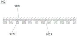
Further, as shown in fig. 15 to 18, the present embodiment further includes a flow stabilizing box 9, and the flow stabilizing box 9 includes a flow stabilizing box body 901 and a flow stabilizing partition 902. The flow stabilizing box body 901 is a rectangular hollow box body, a flow stabilizing box water inlet 903 and a flow stabilizing box water outlet 904 are formed in the flow stabilizing box body 901, the flow stabilizing box water inlet 903 is communicated with a liquid outlet of the liquid delivery pump 5, and the flow stabilizing box water outlet 904 is communicated with the hydraulic screen 3; the flow stabilizing partition 902 is fixedly installed inside the flow stabilizing box body 901, the flow stabilizing partition 902 completely covers the flow stabilizing box water inlet 903 along the projection perpendicular to the flow stabilizing box water inlet 903 direction, and the flow stabilizing box water inlet 903 and the flow stabilizing box water outlet 904 are respectively located on two sides of the flow stabilizing partition 902. In this embodiment, the water inlet 903 of the flow stabilizing box is located on the bottom plate of the flow stabilizing box 901, the water outlet 904 of the flow stabilizing box is located on the same side plate of the flow stabilizing box 901, which faces the hydraulic screen 3, the number of the water outlets 904 of the flow stabilizing box is six, the axes of the six water outlets 904 of the flow stabilizing box are located on the same horizontal plane, that is, the number and the positions of the water outlets 904 of the flow stabilizing box are the same as those of the feed ports 3016 in the hydraulic screen 3, and the water outlets 904 of the flow stabilizing box and the feed ports 3016 on the hydraulic screen 3 are connected in a one-to-one correspondence manner. There may be a mismatch between the water outlet rate of the liquid delivery pump 5 and the feed rate of the hydraulic screen 3, and when the liquid delivery device such as a self-priming pump is discharging water, it is not a smooth and stable water flow, but a water column with a high speed and a large impact force. Under the condition, if the water outlet of the self-sucking pump is directly connected with the water inlet of the hydraulic screen 3, the liquid flowing out of the screen of the hydraulic screen 3 also has large impact force and scatters, and the liquid is sprayed to a sewage treatment site to cause secondary pollution. After the flow stabilizing box 9 in the embodiment is additionally arranged between the liquid delivery pump 5 and the hydraulic screen 3, no matter how fast water flows in from the flow stabilizing box water inlet 903, the water does not directly flow out from the flow stabilizing box water inlet 903, but directly contacts the flow stabilizing partition 902, the impact force of the water flow can act on the flow stabilizing partition 902, the water flow impacting the flow stabilizing partition 902 is converged and accumulated in the flow stabilizing box 901, when the liquid level in the flow stabilizing box 901 gradually rises to the height of the flow stabilizing box water outlet 904, the water in the flow stabilizing box 901 can smoothly flow out from the flow stabilizing box water outlet 904, the effect of reducing water flow impact is achieved, and the situation of liquid splashing cannot occur. It should be noted that when the number of the feed ports 3016 of the hydraulic screen 3 changes, the number of the flow stabilizing box water inlets 903 is changed, and is not limited to the six described in the embodiment.
Further, the flow stabilizing partition 902 in this embodiment is a composite board, and includes a support layer 9021 and a buffer layer 9022. The supporting layer 9021 and the flow stabilizing box body 901 are made of the same material and are both made of stainless steel, the buffer layer 9022 is made of waterproof rubber, and the buffer layer 9022 faces to the water inlet 903 of the flow stabilizing box. In addition, a plurality of buffer grooves 9023 are formed in one surface, away from the supporting layer 9021, of the buffer layer 9022. The buffer layer 9022 can further reduce impact force of water flow, not only can play a role in stabilizing flow, but also can reduce impact on the flow stabilizing partition plate 902, so that stress on the joint of the flow stabilizing partition plate 902 and the flow stabilizing box 901 is reduced, the probability of breakage of the joint of the flow stabilizing partition plate 902 and the flow stabilizing box 901 is reduced, and the service life of the device is prolonged. And the buffer slot 9023 can convert the vertical stress borne by the flow stabilizing partition 902 into a partial transverse stress, so that the effect is further enhanced, and the flow stabilizing box 9 is more durable.
Further, the flow stabilizing partition 902 in this embodiment is a rectangular straight plate, one side of the flow stabilizing partition 902 is fixedly connected to a side plate of the flow stabilizing box 901 where the flow stabilizing box water outlet 904 is located, and a certain interval is provided between two sides of the flow stabilizing partition 902 in the horizontal direction and the side plate of the flow stabilizing box 901 facing the two sides, so that it can be ensured that the liquid in the flow stabilizing box 9 can uniformly rise, rather than being merely stacked on one side of the flow stabilizing partition 902. The extension direction of each buffer slot 9023 is perpendicular to the intersection line of the steady flow partition plate 902 and the side plate of the steady flow box body 901, and the included angle between the steady flow partition plate 902 and the bottom plate of the box body is fifteen to seventy-five degrees.
After using stationary flow case 9 in this embodiment to connect liquid delivery equipment such as self priming pump and hydraulic screen 3, no matter whether liquid delivery equipment and hydraulic screen 3's specification model match, all can pass through the utility model discloses the intercommunication, and the problem that liquid splashes about can not appear, improved the interchangeability of current equipment, when liquid delivery pump 5 or hydraulic screen 3 on equipment processing car or the current processing car broke down promptly, can use current liquid delivery equipment or hydraulic screen 3 to assemble, need not to consider the problem that the power matches, saved the step of purchasing in addition, practiced thrift the cost of enterprise.
Furthermore, the anti-clogging sewage rapid treatment vehicle provided by the embodiment further comprises a high-pressure dredging system 10, wherein the high-pressure dredging system 10 comprises a clean water tank 1001, a dredging machine 1002 and a dredging pipeline 1003 which are sequentially connected, wherein the clean water tank 1001 is fixedly installed on a top plate of the casing box 8 and is located in the casing box 8, the dredging pipeline 1003 is fixedly installed above the chassis of the vehicle body 1, and the dredging machine 1002 is fixedly installed below the chassis of the vehicle body 1. The model of the dredging machine 1002 in the embodiment is UD2715BE, the dredging machine 1002 is installed on the vehicle body 1 after being modified, clean water in the clean water tank 1001 can be pressurized by the dredging machine 1002 and then ejected from the dredging pipeline 1003, meanwhile, a special high-pressure nozzle is arranged at the pipe orifice of the dredging pipeline 1003, the dredging pipeline 1003 has extremely high speed and energy due to the special structure of the nozzle, and substances such as hardened oil stains and caking which are difficult to clean on the inner wall of a sewage pool or pipeline can be crushed or peeled off, so that the substances can be sucked by the grid machine 2 along with sewage for treatment, and the treatment capacity of the anti-clogging sewage rapid treatment vehicle is improved. Meanwhile, the high-pressure dredging system 10 can also be used for cleaning a working site after the sewage in the sewage tank is treated, so that the functionality of the anti-blocking sewage rapid treatment vehicle is improved.
Furthermore, the anti-clogging sewage rapid treatment vehicle provided by the embodiment is further equipped with a corresponding electric cabinet 11, a control handle 12 and a hydraulic oil tank 13 for control, the electric cabinet 11 is internally provided with a signal receiver and a signal processor and is electrically connected with the control handle 12, the hydraulic oil tank 13, a valve on a pipeline and other components, the electric cabinet 11 is provided with a display meter machine control button, and the electric cabinet 11 and the control handle 12 facilitate monitoring of data such as pressure during vehicle operation, control equipment start and stop and the working sequence of related equipment.
Furthermore, the enclosure box 8 of the present embodiment is provided with a plurality of closing doors, and the enclosure box 8 is provided to enclose the above-mentioned grille machine 2 and other devices, so that the vehicle is not interfered by the outside during operation, and the operation stability of the vehicle is improved, but this affects the cleaning, maintenance and other operations of the vehicle, so that the enclosure box 8 is provided with a plurality of closing doors. In addition, the outer case 8 also prevents the collision of key equipment for treating sewage and foreign objects inside the outer case when the vehicle is parked.
It should be noted that the types and specifications of the above-mentioned devices such as the vacuum pump 4, each driving motor, the self-priming pump, the high-pressure dredging machine 1002 are not limited to the types and specifications provided in this embodiment, and under the condition that the types of the components are not changed, the types and specifications can be changed into other types or specifications according to the consideration of the actual cost or requirements, the vacuum pump 4 can adopt a water ring vacuum pump, the butterfly valve can be replaced by a ball valve, and the self-priming pump can also be replaced by a sludge pump.
The utility model provides a pair of prevent blockking up sewage rapid treatment car, at first attract the grid and in with sewage when filtering, just the plastic bag has just been detached when passing through a sieve section of thick bamboo 203 because of sewage this moment, the gentle soft material of large tracts of land such as broken old clothes and food waste, so what grid machine auger 204 extruded all is the solid-liquid mixture that only contains fine granule such as silt, can not take place impurity and articulate the problem at grid machine auger 204, there is not any protruding structure because of sieve section of thick bamboo 203 is inside simultaneously, make the work of clearance sieve section of thick bamboo 203 also very convenient, just so greatly reduced the probability that grid machine 2 blockked up. This is outer because of hydraulic screen 3 has higher treatment effeciency, and when hydraulic screen 3 was used for sewage treatment, BOD got rid of efficiency and equals to approximately equal to first deposit, consequently the utility model discloses a hydraulic screen 3 replaces the flocculation and precipitation equipment in the current processing car, has just so removed the time of waiting for sewage stirring to deposit from, makes the course of treatment become quick, can not appear the condition that flocculation and precipitation blockked up the pipeline again simultaneously. In addition, by additionally arranging the flow stabilizing box 9 and the high-pressure dredging equipment, the sewage treatment site becomes cleaner. To sum up, the embodiment of the utility model provides a have fine practicality, can bring considerable economic benefits.
Example two
As an embodiment of the present invention, the second embodiment is different from the first embodiment in that the steady flow partition 902 is an arc-shaped plate, and the protruding direction of the arc-shaped plate deviates from the steady flow box water inlet 903. The flow stabilizing partition plate 902 is formed by enclosing two straight edges and two arc-shaped edges, the two straight edges are parallel to each other, the shapes and the protruding directions of the two arc-shaped edges are the same, and the trend of each buffer groove 9023 is the same as that of the arc-shaped edge; one straight side is fixedly connected to the bottom plate of the flow stabilizing box 901.
Compared with the first embodiment, when the flow stabilizing partition 902 is impacted by water flow, because the flow stabilizing partition 902 of the first embodiment is arc-shaped, a part of the impact force applied to the flow stabilizing partition 902 is decomposed into the tangential impact force of the arc-shaped edge, so that the flow stabilizing partition 902 has a better force unloading effect, and is less prone to damage.
The above description is only for the preferred embodiment of the present invention, but the scope of the present invention is not limited thereto, and any changes or substitutions that can be easily conceived by those skilled in the art within the technical scope of the present invention should be covered by the present invention.
Claims (8)
1. A stationary flow case for hydraulic screen, characterized by, include
The flow stabilizing box body is provided with a flow stabilizing box water inlet and a flow stabilizing box water outlet, the number of the flow stabilizing box water outlets is multiple, the multiple flow stabilizing box water outlets face to the same side of the flow stabilizing box body, and the axes of the multiple flow stabilizing box water outlets are positioned in the same horizontal plane;
and the flow stabilizing partition board is fixedly arranged inside the flow stabilizing box body, completely covers the water inlet of the flow stabilizing box along a projection perpendicular to the direction of the water inlet of the flow stabilizing box, is a composite board and comprises a supporting layer and a buffer layer.
2. The flow stabilizer box for a hydraulic screen of claim 1, wherein the flow stabilizer water inlet is located on a bottom plate of the flow stabilizer box, the flow stabilizer water outlet is located on one side plate of the flow stabilizer box, and the flow stabilizer water inlet and the flow stabilizer water outlet are located on two sides of the flow stabilizer baffle, respectively.
3. The flow-stabilizing box for the hydraulic screen as claimed in claim 2, wherein the supporting layer and the flow-stabilizing box are made of the same material, the buffer layer is made of waterproof rubber, and the buffer layer faces to the water inlet of the flow-stabilizing box.
4. The flow stabilization box for the hydraulic screen of claim 3, wherein a plurality of buffer grooves are formed in a face of the buffer layer facing away from the support layer.
5. A flow-stabilizing box for a hydraulic screen according to claim 4, wherein the flow-stabilizing baffle is a rectangular straight plate.
6. The flow stabilizing box for the hydraulic screen as claimed in claim 5, wherein one side of the flow stabilizing partition plate is fixedly connected to one side plate of the flow stabilizing box body, the extending direction of each buffer groove is perpendicular to the intersection line of the flow stabilizing partition plate and the side plate of the flow stabilizing box body, and the included angle between the flow stabilizing partition plate and the bottom plate of the box body is 15-75 degrees.
7. The flow stabilizer box for a hydraulic screen of claim 4, wherein the flow stabilizer baffle is an arc-shaped plate, and the protruding direction of the arc-shaped plate is away from the flow stabilizer box water inlet.
8. The flow stabilizing box for the hydraulic screen as claimed in claim 7, wherein the flow stabilizing partition is formed by two straight sides and two arc-shaped sides in a surrounding mode, the two straight sides are parallel to each other, the two arc-shaped sides are identical in shape and protruding direction, and the direction of each buffer groove is identical to that of the arc-shaped side; and one straight edge is fixedly connected to the bottom plate of the flow stabilizing box body.
Priority Applications (1)
| Application Number | Priority Date | Filing Date | Title |
|---|---|---|---|
| CN202022825614.7U CN214243833U (en) | 2020-11-30 | 2020-11-30 | Flow stabilizing box for hydraulic screen |
Applications Claiming Priority (1)
| Application Number | Priority Date | Filing Date | Title |
|---|---|---|---|
| CN202022825614.7U CN214243833U (en) | 2020-11-30 | 2020-11-30 | Flow stabilizing box for hydraulic screen |
Publications (1)
| Publication Number | Publication Date |
|---|---|
| CN214243833U true CN214243833U (en) | 2021-09-21 |
Family
ID=77736689
Family Applications (1)
| Application Number | Title | Priority Date | Filing Date |
|---|---|---|---|
| CN202022825614.7U Active CN214243833U (en) | 2020-11-30 | 2020-11-30 | Flow stabilizing box for hydraulic screen |
Country Status (1)
| Country | Link |
|---|---|
| CN (1) | CN214243833U (en) |
-
2020
- 2020-11-30 CN CN202022825614.7U patent/CN214243833U/en active Active
Similar Documents
| Publication | Publication Date | Title |
|---|---|---|
| CN108856093B (en) | Water-saving efficient ore cleaning equipment | |
| CN111514649A (en) | River silt handles and uses mud-water separation device | |
| CN112079465A (en) | Waste water filtering device for recycling waste lithium batteries | |
| CN214695835U (en) | River channel desilting auxiliary device | |
| CN114405151A (en) | Gravity rotary type sewage treatment device and sewage treatment method | |
| CN112356756A (en) | Prevent blockking up sewage rapid treatment car | |
| CN112605046A (en) | Cleaning and filtering equipment for waste stone processing | |
| CN214243833U (en) | Flow stabilizing box for hydraulic screen | |
| CN214233059U (en) | Prevent blockking up automatic sediment grid machine of arranging | |
| CN214243966U (en) | Slag-adjustable mechanism and hydraulic screen | |
| CN214240564U (en) | Prevent blockking up sewage rapid treatment car | |
| CN112246007A (en) | Desanding and purifying equipment for constructional engineering | |
| CN110627243A (en) | Multistage interception screw press with oil separation and sand settling functions | |
| CN213763140U (en) | Concrete grit separating centrifuge | |
| CN110526541A (en) | A kind of pressafiner | |
| CN112386995A (en) | Prevent blockking up automatic sediment grid machine of arranging | |
| KR101251568B1 (en) | Dehydration process for sludge and apparatus for the same | |
| CN215667442U (en) | Environment-friendly printing and dyeing wastewater treatment device with dispersion structure | |
| CN211078704U (en) | Sewage treatment system | |
| CN214634648U (en) | Thick and thin grid integrated machine | |
| CN213865664U (en) | Prevent food and beverage sewage treatment plant of jam | |
| CN211999086U (en) | Multistage interception screw press with oil separation and sand settling functions | |
| CN210786375U (en) | Chemical pump filter equipment | |
| CN210170923U (en) | Industrial wastewater treatment mud removal device | |
| CN216863702U (en) | Novel cyclone dirt separator |
Legal Events
| Date | Code | Title | Description |
|---|---|---|---|
| GR01 | Patent grant | ||
| GR01 | Patent grant |