CN214634648U - Thick and thin grid integrated machine - Google Patents
Thick and thin grid integrated machine Download PDFInfo
- Publication number
- CN214634648U CN214634648U CN202120543868.1U CN202120543868U CN214634648U CN 214634648 U CN214634648 U CN 214634648U CN 202120543868 U CN202120543868 U CN 202120543868U CN 214634648 U CN214634648 U CN 214634648U
- Authority
- CN
- China
- Prior art keywords
- rotary drum
- machine body
- water
- thin grid
- fine
- Prior art date
- Legal status (The legal status is an assumption and is not a legal conclusion. Google has not performed a legal analysis and makes no representation as to the accuracy of the status listed.)
- Active
Links
Images

Landscapes
- Filtration Of Liquid (AREA)
Abstract
The utility model provides a thick and thin grid integrated machine, including a water distributor, including a organism, the lower terminal surface left and right sides of organism all is provided with the supporting legs, the up end of organism is provided with a water inlet, the up end of organism is provided with the water distributor, the water outlet end of water distributor with the water inlet cooperatees, be provided with the thick grid that inclines downwards between the inner wall of the left and right sides of organism, the water outlet department of organism right-hand member face is provided with the thin grid of rotary drum that is used for filtering filtrating the filtrating in the organism, the left end face of organism is provided with and is used for driving the thin grid of rotary drum rotates driving motor, be provided with the cleaning member that is used for wasing the thin grid of rotary drum on the thin grid of rotary drum, be provided with a storage box between two supporting legs of the left and right sides; the utility model discloses simple structure, the simple operation can carry out solid-liquid separation to sewage.
Description
Technical Field
The utility model relates to a sewage treatment technical field, especially thick, thin grid all-in-one.
Background
Sewage treatment is a process of purifying sewage to meet the water quality requirement of discharging the sewage into a certain water body or reusing the sewage. Sewage treatment is widely applied to various fields such as buildings, agriculture, traffic, energy, petrifaction, environmental protection, urban landscape, medical treatment, catering and the like, and is increasingly used in daily life of common people.
In the prior art, solid-liquid separation is needed for sewage with higher solid content, a coarse grid machine is usually used for filtering large-particle solid in the sewage, then the filtered sewage is input into a fine grid machine, and the grid machine filters small particles in the sewage, so that the solid-liquid separation of the sewage is realized, but the solid-liquid separation of the sewage is carried out through two grid machines, so that the sewage treatment efficiency is reduced, and the sewage treatment method is complex, time-consuming and labor-consuming.
Disclosure of Invention
In view of this, the utility model aims at providing a thick, thin grid all-in-one can carry out solid-liquid separation to sewage.
The utility model discloses a following method realizes: thick, thin grid all-in-one includes a water-locator, its characterized in that: the water distributor comprises a machine body, the lower terminal surface left and right sides of machine body all is provided with the supporting legs, the up end of machine body is provided with a water inlet, the up end of machine body is provided with the water distributor, the play water end of water distributor with the water inlet cooperatees, be provided with the thick grid that inclines to the decurrent between the inner wall about the machine body, the delivery port department of machine body right-hand member face is provided with and is used for filtering the thin grid of rotary drum of filtrating in the machine body, the left end face of machine body is provided with and is used for the drive the thin grid of rotary drum carries out the driving motor who rotates, be provided with on the thin grid of rotary drum and be used for wasing the cleaning member of the thin grid of rotary drum is provided with a storage box between the two supporting legs of the left and right-hand member supporting legs, the right-hand member face of right-hand member supporting legs be provided with be used for with the scarfing cinder piece that the filter residue was cleared up on the thin grid of rotary drum.
Further, the scarfing cinder spare is including being used for with the scraper that the filter residue carries out the clearance on the filter screen of the thin grid of rotary drum, and the right-hand member face of right-hand member supporting legs is provided with one and goes out the slag hopper, it installs on the inner wall of bucket to go out the slag the scraper, it is provided with to be used for with to go out the preceding terminal surface of bucket the scraper is fixed bolt in the bucket of going out the slag, it is provided with and is used for collecting to go out the slag hopper below go out the collecting box of waste residue in the discharge of the slag hopper.
Furthermore, the cleaning part comprises a plurality of spray heads used for cleaning the fine rotary drum grating, a plurality of water outlet branch pipes are arranged on the inner wall of the fine rotary drum grating, the spray heads are arranged at the output ends of the water outlet branch pipes, the water inlet ends of the water outlet branch pipes are connected through a water inlet pipe, the water inlet pipe is positioned in the inner wall of the fine rotary drum grating, and the water inlet end of the water inlet pipe is positioned outside the fine rotary drum grating.
Furthermore, an overflow pipe is arranged on the lower end face of the machine body.
Furthermore, a water outlet pipe is arranged on the left end face of the storage box.
Furthermore, a slag hole for conveying the filter residue in the machine body to the outside of the machine body is formed in the right end face of the machine body.
The beneficial effects of the utility model reside in that: the utility model adds the coarse grating and the drum fine grating, the coarse grating can separate the large granular solid in the sewage from the sewage, the drum fine grating can separate the large granular solid in the sewage from the sewage, and the solid-liquid separation of the solid in the sewage is realized; the spray head is added in the device, and can clean the filter screen on the fine drum grating and prevent the filter screen of the fine drum grating from being blocked, thereby being beneficial to improving the efficiency of sewage treatment; the scraper, the slag discharge hopper, the collecting box and the slag discharge hole are added into the device, filter residues on a filter screen of the drum fine grating can be scraped and rubbed by the scraper and enter the collecting box through the slag discharge hopper for storage, and the filter residues in the machine body enter the collecting box through the slag discharge hole for storage under the action of gravity, so that the coarse grating and the drum fine grating can continuously work, and the efficiency of solid-liquid separation of sewage is improved; the utility model discloses simple structure, the simple operation can carry out solid-liquid separation to sewage.
Drawings
Fig. 1 is a schematic structural diagram of the present invention.
Fig. 2 is a left side view of the present invention.
Fig. 3 is a top view of the present invention.
Fig. 4 is a schematic circuit block diagram of the present invention.
Detailed Description
The present invention will be further explained with reference to the accompanying drawings.
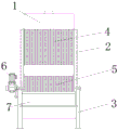
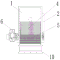
Referring to fig. 1 to 4, the present invention provides an embodiment of a thick and thin grid integrated machine, including a water distributor 1, the type of the water distributor 1 may be JM5402, but is not limited thereto, including a machine body 2, the left and right sides of the lower end surface of the machine body 2 are provided with support legs 3, the upper end surface of the machine body 2 is provided with a water inlet (not shown), the upper end surface of the machine body 2 is provided with the water distributor 1, the water outlet end of the water distributor 1 is matched with the water inlet to introduce sewage into the water distributor 1, then the sewage is decompressed, uniformly distributed and dispersed, finally enters the machine body 2 through the water inlet of the machine body 2, a downward inclined thick grid 4 is arranged between the left and right inner walls of the machine body 2, the water outlet of the right end surface of the machine body 2 is provided with a fine drum grid 5 for filtering filtrate in the machine body 2, the sewage firstly passes through a coarse grating 4 for carrying out first solid-liquid separation, large particles in the sewage are intercepted at the top of the coarse grating 4, the sewage filtered by a coarse grating 4 machine enters the bottom of the coarse grating 4 and then flows into a rotary drum fine grating 5, a driving motor 6 for driving the rotary drum fine grating 5 to rotate is arranged on the left end surface of the machine body 2, the driving motor 6 is a driving motor 6 with a speed reducer, the driving motor 6 drives the rotary drum fine grating 5 to rotate and carries out solid-liquid separation on the sewage in the rotary drum fine grating 5, a cleaning piece (not shown) for cleaning the rotary drum fine grating 5 is arranged on the rotary drum fine grating 5, a storage box 7 is arranged between a left supporting foot and a right supporting foot 3, filtrate filtered by the rotary drum fine grating 5 is input into the storage box 7 for storage, and a slag cleaning piece 8 for cleaning slag on the rotary drum fine grating 5 is arranged on the right end surface of the supporting foot 3, the slag removing piece 8 can remove filter residues on the filter screen of the fine drum grating 5, so that the fine drum grating 5 is prevented from being blocked.
With reference to fig. 1 and fig. 3, the slag removing component 8 includes a scraper 9 for cleaning the filter residue on the filter screen of the drum fine grid 5, a residue discharge hopper 10 is disposed on the right end face of the right support leg 3, the scraper 9 is mounted on the inner wall of the residue discharge hopper 10, a bolt 11 for fixing the scraper 9 in the residue discharge hopper 10 is disposed on the front end face of the residue discharge hopper 10, a collecting box 12 for collecting the waste residue in the discharge of the residue discharge hopper 10 is disposed below the residue discharge hopper 10, and the scraper 9 can scrape the filter residue on the filter screen of the drum fine grid 5 into the residue discharge hopper 10 and store the filter residue in the collecting box 12 through the residue discharge hopper 10.
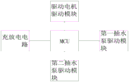
With reference to fig. 1 to 4, the cleaning member includes a plurality of spray headers (not shown) for cleaning the fine drum grating 5, the inner wall of the fine drum grating 5 is provided with a plurality of water outlet pipes (not shown), the output ends of the water outlet pipes are provided with the spray headers (not shown), the water inlet ends of the water outlet pipes are connected through a water inlet pipe (not shown), the water inlet pipe is located in the inner wall of the fine drum grating 5, the water inlet end of the water inlet pipe is located outside the fine drum grating 5, the water inlet end of the water inlet pipe is provided with a first water pump (not shown) for pumping external water into the spray headers, the first water pump pumps the external water into the water inlet pipe, the water in the water inlet pipe enters the spray headers through the water outlet pipes, the spray headers spray the water onto the filter screens of the fine drum grating 5 for cleaning, so as to prevent the filter screens of the fine drum grating 5 from being blocked, the water inlet of water distributor 1 is connected with raceway (not shown in the figure), be provided with on the raceway and pump outside sewage and deliver to second suction pump (not shown in the figure) in the water distributor 1, in the second suction pump pumps outside sewage through the raceway and delivers to water distributor 1, the left end face of left end supporting legs 3 is provided with a control box (not shown in the figure), be provided with a circuit board (not shown in the figure) in the control box and be used for right the power supply box (not shown in the figure) that the circuit board carries out the power supply, the power supply box can supply power to the circuit board, be provided with MCU on the circuit board, MCU's model can be STM32F19T4, but not limited to this, MCU is connected with driving motor drive module, charge and discharge circuit, first suction pump drive module and second suction pump drive module, and the power supply box can be the circuit board power supply through charge and discharge circuit, and the circuit board can be to driving motor drive module, Charging and discharging circuit, first suction pump drive module and second suction pump drive module supply power, the staff can be through the operating time of the first suction pump of time knob control on the control box, thereby the time of time knob control shower head spraying has been realized, when the staff carries out the during operation through control box drive second suction pump, the control box can work by automatic control driving motor 6, when the staff starts driving motor 6 through the control box and carries out the during operation, the control box can work by automatic drive second suction pump, the linkage of driving motor 6 and second suction pump has been realized.
As shown in fig. 1, an overflow pipe 13 is disposed on the lower end surface of the machine body 2, and when the fine drum grid 5 is blocked, the overflow pipe 13 can convey the filtrate in the machine body 2 to the previous step.
Referring to fig. 1, a water outlet pipe 14 is disposed on a left end surface of the storage tank 7, a solenoid valve (not shown) is disposed on the water outlet pipe 14, and the water outlet pipe 14 can convey the filtrate in the storage tank 7 to the next step.
As shown in fig. 1 to fig. 3, a slag outlet (not shown) for conveying the filter residue in the machine body 2 to the outside of the machine body 2 is formed in the right end face of the machine body 2, the filter residue in the machine body 2 falls from the slag outlet to the outer surface of the fine drum grating 5 under the action of gravity, and then the fine drum grating 5 can guide the filter residue falling from the outer surface of the fine drum grating 5 into a slag discharge hopper 10 through a scraper 9 under the driving of a driving motor 6, and then the filter residue is conveyed into a collection box 12 through the slag discharge hopper 10 for storage.
The utility model discloses the theory of operation: when the device is used, sewage is conveyed into the water distributor for pressure reduction, uniform distribution and dispersion treatment, the sewage is conveyed into the machine body after being treated, the sewage is subjected to first solid-liquid separation by the coarse grating in the machine body, large particles are fixedly retained at the top of the coarse grating, filtrate enters the bottom of the coarse grating and enters the fine grating of the rotary drum through the water outlet of the machine body, the fine grating of the rotary drum is driven to rotate by the driving motor, small particle solids in the sewage are separated from the sewage by the filter screen on the fine grating of the rotary drum while the fine grating of the rotary drum rotates, the surface of the filter screen of the fine grating of the rotary drum is cut and rubbed under the action of the scraper, filter residues are cleaned into the collection box, the filtrate filtered by the fine grating of the rotary drum enters the storage box for storage, and then the filtrate in the storage box can be conveyed to the next step for treatment through the water outlet pipe.
The utility model provides a control box, the thin grid of rotary drum, thick grid, power box, circuit board, first suction pump, second suction pump, solenoid valve, driving motor drive module, charge-discharge circuit, first suction pump drive module and second suction pump drive module's circuit principle and structure are prior art, and the technical personnel in the field have clearly been known, do not explain in detail here, just the utility model discloses what protect is the structural feature of thick, thin grid all-in-one.
The above is only the preferred embodiment of the present invention, and all the equivalent changes and modifications made according to the claims of the present invention should be covered by the present invention.
Claims (6)
1. Thick, thin grid all-in-one includes a water-locator, its characterized in that: the water distributor comprises a machine body, the lower terminal surface left and right sides of machine body all is provided with the supporting legs, the up end of machine body is provided with a water inlet, the up end of machine body is provided with the water distributor, the play water end of water distributor with the water inlet cooperatees, be provided with the thick grid that inclines to the decurrent between the inner wall about the machine body, the delivery port department of machine body right-hand member face is provided with and is used for filtering the thin grid of rotary drum of filtrating in the machine body, the left end face of machine body is provided with and is used for the drive the thin grid of rotary drum carries out the driving motor who rotates, be provided with on the thin grid of rotary drum and be used for wasing the cleaning member of the thin grid of rotary drum is provided with a storage box between the two supporting legs of the left and right-hand member supporting legs, the right-hand member face of right-hand member supporting legs be provided with be used for with the scarfing cinder piece that the filter residue was cleared up on the thin grid of rotary drum.
2. The coarse and fine grid integrated machine according to claim 1, wherein: the scarfing cinder spare is including being used for with the scraper that the filter residue was cleared up on the filter screen of the thin grid of rotary drum, and the right-hand member face of right-hand member supporting legs is provided with one and goes out the slag bucket, it installs on the inner wall of slag bucket the scraper to go out, the preceding terminal surface of slag bucket be provided with be used for with the scraper is fixed bolt in the slag bucket, it is provided with and is used for collecting to go out the slag bucket below go out the collecting box of slag bucket ejection of compact interior waste residue.
3. The coarse and fine grid integrated machine according to claim 1, wherein: the cleaning part comprises a plurality of spray heads used for cleaning the rotary drum fine grating, a plurality of water outlet branch pipes are arranged on the inner wall of the rotary drum fine grating, the output ends of the water outlet branch pipes are provided with the spray heads, the water inlet ends of the water outlet branch pipes are connected through a water inlet pipe, the water inlet pipe is located in the inner wall of the rotary drum fine grating, and the water inlet end of the water inlet pipe is located outside the rotary drum fine grating.
4. The coarse and fine grid integrated machine according to claim 1, wherein: an overflow pipe is arranged on the lower end face of the machine body.
5. The coarse and fine grid integrated machine according to claim 1, wherein: and a water outlet pipe is arranged on the left end surface of the storage box.
6. The coarse and fine grid integrated machine according to claim 1, wherein: and a slag outlet for conveying the filter residue in the machine body to the outside of the machine body is formed in the right end face of the machine body.
Priority Applications (1)
| Application Number | Priority Date | Filing Date | Title |
|---|---|---|---|
| CN202120543868.1U CN214634648U (en) | 2021-03-16 | 2021-03-16 | Thick and thin grid integrated machine |
Applications Claiming Priority (1)
| Application Number | Priority Date | Filing Date | Title |
|---|---|---|---|
| CN202120543868.1U CN214634648U (en) | 2021-03-16 | 2021-03-16 | Thick and thin grid integrated machine |
Publications (1)
| Publication Number | Publication Date |
|---|---|
| CN214634648U true CN214634648U (en) | 2021-11-09 |
Family
ID=78455252
Family Applications (1)
| Application Number | Title | Priority Date | Filing Date |
|---|---|---|---|
| CN202120543868.1U Active CN214634648U (en) | 2021-03-16 | 2021-03-16 | Thick and thin grid integrated machine |
Country Status (1)
| Country | Link |
|---|---|
| CN (1) | CN214634648U (en) |
Cited By (1)
| Publication number | Priority date | Publication date | Assignee | Title |
|---|---|---|---|---|
| CN115400496A (en) * | 2022-08-24 | 2022-11-29 | 安徽欧石环保科技有限公司 | Sewage filtering device in primary sewage treatment system |
-
2021
- 2021-03-16 CN CN202120543868.1U patent/CN214634648U/en active Active
Cited By (1)
| Publication number | Priority date | Publication date | Assignee | Title |
|---|---|---|---|---|
| CN115400496A (en) * | 2022-08-24 | 2022-11-29 | 安徽欧石环保科技有限公司 | Sewage filtering device in primary sewage treatment system |
Similar Documents
| Publication | Publication Date | Title |
|---|---|---|
| CN206588076U (en) | A kind of Chinese medicinal material cleaning machine | |
| CN2910324Y (en) | Micro solid/liquid separator | |
| CN218655776U (en) | Sand washing device | |
| CN214634648U (en) | Thick and thin grid integrated machine | |
| CN216997916U (en) | Municipal sewage circulation treatment equipment convenient to clearance sewage isolate | |
| CN108745616A (en) | A kind of aggregate screening device with sludge clearing function | |
| CN215614043U (en) | Soil prosthetic devices of usefulness is administered to environment | |
| CN112246007A (en) | Desanding and purifying equipment for constructional engineering | |
| CN209865407U (en) | Filter press | |
| CN110627243A (en) | Multistage interception screw press with oil separation and sand settling functions | |
| CN210170973U (en) | Rotating drum micro-filter of excrement and sewage separation equipment for aquaculture wastewater | |
| CN214767507U (en) | Traditional chinese medicine medicinal material belt cleaning device | |
| CN113877298A (en) | Mud treatment facility for engineering construction | |
| CN211999086U (en) | Multistage interception screw press with oil separation and sand settling functions | |
| CN111359966B (en) | Continuous flushing machine for waste plastic fragments | |
| CN211521799U (en) | Sewage grading cleaning environment-friendly device | |
| CN112356756A (en) | Prevent blockking up sewage rapid treatment car | |
| KR20100021331A (en) | Apparatus for separating a floating from recyclable aggregate | |
| CN214240564U (en) | Prevent blockking up sewage rapid treatment car | |
| CN214528391U (en) | Kitchen wastewater treatment all-in-one machine | |
| CN214233059U (en) | Prevent blockking up automatic sediment grid machine of arranging | |
| CN220835864U (en) | Automatic breaker of dust removal | |
| CN214319635U (en) | Be used for kibbling dust collector of scrap iron | |
| CN213433190U (en) | Domestic sewage treatment prevents stifled filtration equipment | |
| CN215656679U (en) | Ore belt cleaning device for ore mining |
Legal Events
| Date | Code | Title | Description |
|---|---|---|---|
| GR01 | Patent grant | ||
| GR01 | Patent grant |