CN214238558U - Slitting mill for cutting PCB (printed circuit board) substrate - Google Patents
Slitting mill for cutting PCB (printed circuit board) substrate Download PDFInfo
- Publication number
- CN214238558U CN214238558U CN202023077319.4U CN202023077319U CN214238558U CN 214238558 U CN214238558 U CN 214238558U CN 202023077319 U CN202023077319 U CN 202023077319U CN 214238558 U CN214238558 U CN 214238558U
- Authority
- CN
- China
- Prior art keywords
- cutter
- pinch roller
- motor
- main shaft
- synchronizing wheel
- Prior art date
- Legal status (The legal status is an assumption and is not a legal conclusion. Google has not performed a legal analysis and makes no representation as to the accuracy of the status listed.)
- Active
Links
Images


Landscapes
- Perforating, Stamping-Out Or Severing By Means Other Than Cutting (AREA)
Abstract
The utility model relates to the field of PCB processing, in particular to a slitting mill for cutting PCB substrates, which comprises a hobbing cutter component for cutting materials longitudinally; the cutter assembly is used for transversely cutting the material; the pushing assembly is used for pushing materials; still be equipped with left mainboard and right mainboard and make the propelling movement subassembly hobbing cutter subassembly with the cutter subassembly is the level setting in the middle of two mainboards, the propelling movement subassembly with the hobbing cutter subassembly with cutter subassembly interval sets up, and integrated hobbing cutter is opened material and the cutter is opened material, reduces the process of transporting in the middle of twice material of opening simultaneously, realizes efficient base plate and opens the material function, reduces equipment cost.
Description
Technical Field
The utility model relates to a PCB board processing field indicates a slitting mill for PCB base plate is opened material especially.
Background
The PCB board processing is preceded with cutting the PCB base plate, traditional base plate is cut the material and is carried out the first time and open the board in an equipment, and the direction that will change the base plate is carried out the second time again and is opened the board or is sent to another equipment and carry out the second time and open the board in order to raise the efficiency, and this kind of mode of opening the board is because the process flow is not coherent, causes unnecessary consuming time, the big problem of equipment area in addition simultaneously.
Patent document CN 210256491U discloses a circuit board cutting device, which is provided with a first cutting line and a second cutting line, and is characterized in that the cutting lines are provided with an upper cutter and a lower cutter to cut a PCB board simultaneously, thereby improving the cutting efficiency.
The cutting device of the above patent document can only cut the PCB board in a single direction, if the large PCB board needs to be divided into small pieces, the cutting operation needs to be repeated, the efficiency is very low, and if the equipment is added, the equipment cost is too high, so that the equipment capable of efficiently cutting the substrate is needed.
Disclosure of Invention
In order to solve the problem, the utility model provides a slitting mill for PCB base plate is opened material, integrated hobbing cutter is opened material and cutter is opened material, reduces the process of transporting in the middle of twice material of opening simultaneously, realizes efficient base plate and opens material function, reduces equipment cost.
In order to achieve the above object, the utility model adopts the following technical scheme:
a slitting mill for cutting a PCB substrate comprises a hob assembly, a slitting roller and a slitting roller, wherein the hob assembly is used for longitudinally cutting a material;
the cutter assembly is used for transversely cutting the material;
the pushing assembly is used for pushing materials;
still be equipped with left mainboard and right mainboard and make the propelling movement subassembly hobbing cutter subassembly with the cutter subassembly is the level setting in the middle of two mainboards, the propelling movement subassembly with the hobbing cutter subassembly with the cutter subassembly interval sets up.
Preferably, the hobbing cutter subassembly includes hobbing cutter motor, transmission gear group, hobbing cutter main shaft, hobbing cutter and hobbing cutter axle center, hobbing cutter motor and transmission gear group this are in the outside of right side mainboard, the hobbing cutter main shaft divide into upper slitter main shaft and lower slitter main shaft, and is a plurality of the hobbing cutter is fixed through the installation on the hobbing cutter main shaft and be in respectively the upper slitter main shaft with the relative position of lower slitter main shaft, the hobbing cutter main shaft with the both sides in hobbing cutter axle center are respectively through swing joint left side mainboard with right side mainboard, the hobbing cutter main shaft with the both ends in hobbing cutter axle center are connected respectively the transmission gear group, the hobbing cutter motor is established the below in transmission gear group is connected the transmission gear group.
The power of the hob motor drives the hob main shaft and the hob shaft core to rotate through the transmission gear set, the hob arranged on the hob main shaft is driven to rotate at the same time, and therefore the power for cutting the hob is generated, and meanwhile, because the hob cuts through the upper hob main shaft and the lower hob main shaft at the same time, the cutting efficiency is greatly improved.
Preferably, drive gear group includes motor gear, drive gear, accent sword sprocket, arbor drive gear and chain, motor gear establishes the output of hobbing cutter motor, the accent sword sprocket is established respectively go up the both ends of sword main shaft, arbor drive gear establishes respectively go up the sword main shaft with lower sword main shaft is close to the one end of right side mainboard, drive gear establishes respectively the both ends in hobbing cutter axle center, motor gear passes through the chain is connected drive gear, two drive gear passes through respectively two are connected to the chain accent sword sprocket, two arbor drive gear meshes mutually.
The hob cutter motor drives the transmission gear to rotate through the motor gear and the chain, the transmission gear is connected with the hob cutter axis, so that the transmission gears at two ends of the hob cutter axis rotate simultaneously, the transmission gear drives the cutter adjusting chain wheel to rotate through the chain, the upper cutter main shaft rotates, and meanwhile, the upper cutter main shaft and the lower cutter main shaft are both provided with the cutter shaft transmission gears which are meshed with each other, so that the lower cutter main shaft is further driven to rotate, cutting power of the hob cutter assembly is provided, and longitudinal cutting of the hob cutter is achieved.
Preferably, the cutter assembly comprises a cutter motor, an upper cutter, a lower cutter, a cutter axis, an eccentric wheel and a cutter connecting rod, the cutter connecting rod is respectively arranged at the outer sides of the left main board and the right main board, the upper cutter and the lower cutter are arranged between the left main board and the right main board, the lower cutter is fixedly connected with the left main board and the right main board, two ends of the upper cutter are respectively connected with one end of the cutter connecting rod, the other end of the cutter connecting rod is connected with the cutter axis through the eccentric wheel, and the cutter motor is arranged in the middle of the cutter axis.
The cutter motor simultaneously generates rotating power to the eccentric wheels on the two sides through the cutter shaft core, so that the cutter connecting rods on the two sides generate periodic up-and-down motion, the upper cutter is driven to move up and down, and the lower cutter is matched to realize transverse cutting of the cutter.
Preferably, the middle of the cutter connecting rod is further provided with a sliding rail and a sliding block, the two sliding rails are respectively fixed on the outer sides of the left main board and the right main board in parallel along the vertical direction, and the sliding block is connected with the cutter connecting rod and slides on the sliding rails.
The eccentric wheel periodically pushes the cutter connecting rod to enable the cutter connecting rod to move up and down along the direction of the sliding rail through the sliding block, and the cutter connecting rod is prevented from deviating.
Preferably, the propelling movement subassembly includes pinch roller, cylinder group, propelling movement motor and transmission wheelset, the pinch roller is established left side mainboard with the centre of right side mainboard, the pinch roller with hob assembly with the cutter subassembly interval sets up, the pinch roller divide into initiative pinch roller and passive pinch roller, passive pinch roller and initiative pinch roller correspond the setting from top to bottom respectively, the transmission wheelset is established the pinch roller is close to the one end of left side mainboard is connected the initiative pinch roller, the initiative pinch roller is close to swing joint is passed through to the one end of right side mainboard, cylinder group fixes respectively left side mainboard with the outside of right side mainboard, and connect passive pinch roller, the propelling movement motor is fixed the inboard of left side mainboard.
The propelling movement motor provides the operating power of propelling movement subassembly, through the drive wheelset drives the initiative pinch roller rotates, passive pinch roller passes through cylinder group produces decurrent pressure, cooperates the centre gripping and the propelling movement of initiative pinch roller realization to the PCB board.
Preferably, the transmission wheelset includes motor synchronizing wheel, pinch roller synchronizing wheel, suppression servo synchronizing wheel, idler and belt, pinch roller synchronizing wheel difference fixed connection the initiative pinch roller, suppression servo synchronizing wheel is through connecting the lower sword main shaft, the idler is established pinch roller synchronizing wheel with the top of suppression servo synchronizing wheel, and with pinch roller synchronizing wheel with the crisscross setting of being close to of suppression servo synchronizing wheel, motor synchronizing wheel connects the propelling movement motor, motor synchronizing wheel passes through the belt is connected pinch roller synchronizing wheel with suppression servo synchronizing wheel.
The motor synchronizing wheel drives the pinch roller synchronizing wheel and the pressing servo motor synchronizing wheel to rotate simultaneously through the belt, and the belt is prevented from slipping in the working process through extrusion of the idle wheel.
The beneficial effects of the utility model reside in that:
the continuous longitudinal cutting function of the hob and the transverse cutting function of the cutter are integrated in a limited space, so that the acquisition cost of equipment is reduced, the process of changing the direction of the substrate is saved through the pushing assembly, and the cutting efficiency is greatly improved; the pushing assembly is arranged alternately with the hob assembly and the cutter assembly respectively, the layout is reasonably arranged, and the occupied space of equipment is reduced.
Drawings
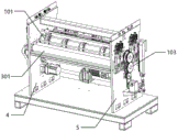
Fig. 1 is a schematic structural diagram of the present invention.
Fig. 2 is a schematic structural diagram of the present invention.
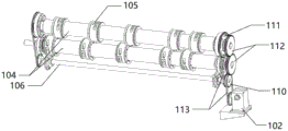
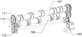
Fig. 3 is a schematic view of the hob assembly of the present invention.
Fig. 4 is a schematic view of the hob assembly of the present invention.
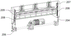
Fig. 5 is a schematic view of the cutter assembly of the present invention.
Fig. 6 is a schematic view of the cutter assembly of the present invention.
Fig. 7 is a schematic view of the pushing assembly of the present invention.
Fig. 8 is a schematic view of the pushing assembly of the present invention.
The reference numbers illustrate: 101. a hob assembly; 102. a hob motor; 103. a drive gear set; 104. a hob main shaft; 105. hobbing cutters; 106. the axis of the hobbing cutter; 107. a tool mounting main shaft; 108. a lower cutter main shaft; 109. a motor gear; 110. a transmission gear; 111. a cutter adjusting chain wheel; 112. a cutter shaft transmission gear; 113. a chain; a cutter assembly; 202. a cutter motor; 203. an upper cutter; 204. a lower cutter; 205. the axis of the cutter; 206, eccentric wheel; 207. a cutter connecting rod; 208. a slide rail; 209. a slider; 301. a push assembly; 302. a pinch roller; 303. a cylinder group; 304. a pushing motor; 305. a transmission wheel set; 306. an active pinch roller; 307. a passive pinch roller; 308. a motor synchronizing wheel; 309. a pinch roller synchronizing wheel; 310. pressing a servo synchronous wheel; 311. an idler pulley; 312. a belt; 4. a left main board; 5. and a right main board.
Detailed Description
Referring to fig. 1-8, the present invention relates to a slitting mill for cutting PCB substrates, which comprises a hob assembly 101 for cutting the material longitudinally;
the cutter assembly 201 is used for transversely cutting the material;
the pushing assembly 301 is used for pushing materials;
still be equipped with left mainboard 4 and right mainboard 5 and make propelling movement subassembly 301 hobbing cutter subassembly 101 with cutter subassembly 201 is the level setting in the middle of two mainboards, propelling movement subassembly 301 with hobbing cutter subassembly 101 with cutter subassembly 201 interval sets up.
As shown in fig. 3-4, the hob assembly 101 includes a hob motor 102, a transmission gear set 103, a hob spindle 104, a hob 105 and a hob spindle axis 106, the hob motor 102 and the transmission gear set 103 are located outside the right main plate 5, the hob spindle 104 is divided into an upper hob spindle 107 and a lower hob spindle 108, the hobs 105 are fixed on the hob spindle 104 by installation and are respectively located at the relative positions of the upper hob spindle 107 and the lower hob spindle 108, the two sides of the hob spindle 104 and the two sides of the hob spindle axis 106 are respectively movably connected to the left main plate 4 and the right main plate 5, the two ends of the hob spindle 104 and the two ends of the hob axis 106 are respectively connected to the transmission gear set 103, and the hob motor 102 is located below the transmission gear set 103 and is connected to the transmission gear set 103.
The power of the hob motor 102 drives the hob spindle 104 and the hob shaft center 106 to rotate through the transmission gear set 103, the hob 105 mounted on the hob spindle 104 is simultaneously driven to rotate, so that the power for hob cutting is generated, and meanwhile, because the hob 105 simultaneously cuts through the upper hob spindle 107 and the lower hob spindle 108, the cutting efficiency is greatly improved.
The hob cutter motor 102 drives the transmission gear 110 to rotate through the motor gear 109 and the chain 113, the transmission gear 110 is connected with the hob cutter shaft center 106, so that the transmission gears 110 at two ends of the hob cutter shaft center 106 simultaneously rotate, and then the transmission gear 110 drives the cutter adjusting chain wheel 111 to rotate through the chain 113, so that the upper cutter main shaft 107 rotates, and meanwhile, the upper cutter main shaft 107 and the lower cutter main shaft 108 are both provided with the cutter shaft transmission gear 112 which is meshed with each other, so that the lower cutter main shaft 108 is further driven to rotate, so that cutting power of the hob cutter assembly 101 is provided, and the hob cutter is longitudinally opened.
The hob 105 is fixed on the hob main shaft 104 through installation, the number of the hobs 105 can be increased or decreased according to actual requirements, and the positions of the hobs 105 can be changed, so that the required longitudinal cutting number and cutting positions can be realized.
As shown in fig. 5-6, the cutter assembly includes a cutter motor 202, an upper cutter 203, a lower cutter 204, a cutter shaft 205, an eccentric wheel 206 and a cutter connecting rod 207, the cutter connecting rod 207 is respectively disposed at the outer sides of the left main plate 4 and the right main plate 5, the upper cutter 203 and the lower cutter 204 are disposed between the left main plate 4 and the right main plate 5, the lower cutter 204 is fixedly connected to the left main plate 4 and the right main plate 5, two ends of the upper cutter 203 are respectively connected to one end of the two cutter connecting rods 205, the other end of the cutter connecting rod 205 is connected to the cutter shaft 207 through the eccentric wheel 206, and the cutter motor 202 is disposed in the middle of the cutter shaft 207.
The cutter motor 202 simultaneously generates rotating power to the eccentric wheels 206 on both sides through the cutter shaft 207, so that the cutter connecting rods 207 on both sides generate periodic up-and-down motion, and further drive the upper cutter 203 to move up and down, and the lower cutter 204 is matched to realize transverse cutting of the cutter.
The middle of the cutter connecting rod 207 is also provided with a sliding rail 208 and a sliding block 209, the two sliding rails 208 are respectively fixed on the outer sides of the left main board 4 and the right main board 5 in parallel along the vertical direction, and the sliding block 209 is connected with the cutter connecting rod 207 and slides on the sliding rail 208.
The eccentric wheel 206 periodically pushes the cutter connecting rod 207, so that the cutter connecting rod 207 moves up and down along the direction of the sliding rail 208 through the sliding block 209, and the cutter connecting rod 207 is prevented from deviating.
As shown in fig. 7-8, the pushing assembly includes a pressing wheel 302, a cylinder group 303, a pushing motor 304 and a driving wheel group 305, the pressing wheel 304 is disposed between the left main board 4 and the right main board 5, the pressing wheel 302 is spaced from the hob assembly 101 and the cutter assembly 201, the pressing wheel 302 is divided into an active pressing wheel 306 and a passive pressing wheel 307, the passive pressing wheel 307 and the active pressing wheel 306 are respectively disposed up and down, the driving wheel group 305 is disposed at a position where the pressing wheel 302 is close to one end of the left main board 4 and connected to the active pressing wheel 306, the active pressing wheel 306 is close to one end of the right main board 5 and movably connected to the right main board 5, the cylinder group 303 is respectively fixed at the outer sides of the left main board 4 and the right main board 5 and connected to the passive pressing wheel 307, and the pushing motor 304 is fixed at the inner side of the left main board 4.
The pushing motor 304 provides working power for the pushing assembly 301, the driving wheel set 305 drives the driving pressure wheel 306 to rotate, the driven pressure wheel 307 generates downward pressure through the cylinder set 303, and the driving pressure wheel 306 is matched to clamp and push the PCB.
The transmission wheel set 305 comprises a motor synchronizing wheel 308, a pressure wheel synchronizing wheel 309, a pressing servo synchronizing wheel 310, an idle wheel 311 and a belt 312, wherein the pressure wheel synchronizing wheel 309 is fixedly connected with the driving pressure wheel 306, the pressing servo synchronizing wheel 310 is connected with the lower cutter spindle 108, the idle wheel 311 is arranged above the pressure wheel synchronizing wheel 309 and the pressing servo synchronizing wheel 310 and is close to the pressure wheel synchronizing wheel 309 and the pressing servo synchronizing wheel 310 in a staggered mode, the motor synchronizing wheel 308 is connected with the pushing motor 304, and the motor synchronizing wheel 308 is connected with the pressure wheel synchronizing wheel 309 and the pressing servo synchronizing wheel 310 through the belt 312.
The motor synchronous wheel drives the pressure wheel synchronous wheel 309 and the pressing servo motor synchronous wheel 310 to rotate simultaneously through the belt 312, and the idle wheel 311 extrudes the belt 312 to prevent the belt 312 from slipping in the working process.
The utility model discloses a theory of operation is:
a whole PCB substrate is pushed to the hob assembly 101 through the active pinch roller 306 and the passive pinch roller 307 of the pushing assembly 301, and is cut up and down simultaneously through the hob 105 on the upper knife main shaft 107 and the lower knife main shaft 108, so that the substrate is longitudinally divided into a plurality of blocks; and then the substrate which is longitudinally divided is sent to the cutter assembly 201 by the pushing assembly 301 for transverse cutting, so that the cutting of the substrate is completed.
The beneficial effects of the utility model reside in that:
the continuous longitudinal cutting function of the hob and the transverse cutting function of the cutter are integrated in a limited space, so that the acquisition cost of equipment is reduced, the process of changing the direction of the substrate is saved through the pushing assembly, and the cutting efficiency is greatly improved; the pushing assembly is arranged alternately with the hob assembly and the cutter assembly respectively, the layout is reasonably arranged, and the occupied space of equipment is reduced.
The above embodiments are only for describing the preferred embodiments of the present invention, and are not intended to limit the scope of the present invention, and various modifications and improvements made by the technical solution of the present invention by those skilled in the art are all within the scope of the present invention as defined by the claims.
Claims (7)
1. The utility model provides a slitting mill for PCB base plate is opened material which characterized in that: comprises a hobbing cutter component used for cutting the material longitudinally;
the cutter assembly is used for transversely cutting the material;
the pushing assembly is used for pushing materials;
still be equipped with left mainboard and right mainboard and make the propelling movement subassembly hobbing cutter subassembly with the cutter subassembly is the level setting in the middle of two mainboards, the propelling movement subassembly with the hobbing cutter subassembly with the cutter subassembly interval sets up.
2. The slitting mill for PCB substrate slitting as recited in claim 1, wherein: the hobbing cutter subassembly includes hobbing cutter motor, drive gear group, hobbing cutter main shaft, hobbing cutter and hobbing cutter axle center, hobbing cutter motor and drive gear group are in the outside of right side mainboard, the hobbing cutter main shaft divide into upper slitter main shaft and lower slitter main shaft, and is a plurality of the hobbing cutter is fixed through the installation on the hobbing cutter main shaft and be in respectively the upper slitter main shaft with the relative position of lower slitter main shaft, the hobbing cutter main shaft with the both sides in hobbing cutter axle center are respectively through swing joint left side mainboard with right side mainboard, the hobbing cutter main shaft with the both ends in hobbing cutter axle center are connected respectively drive gear group, the hobbing cutter motor is established the below in drive gear group is connected drive gear group.
3. The slitting mill for PCB substrate slitting as recited in claim 2, wherein: drive gear set includes motor gear, drive gear, knife adjustment sprocket, arbor drive gear and chain, motor gear establishes the output of hobbing cutter motor, the knife adjustment sprocket is established respectively the both ends of upper slitter main shaft, arbor drive gear establishes respectively the upper slitter main shaft with lower slitter main shaft is close to the one end of right side mainboard, drive gear establishes respectively the both ends in hobbing cutter axle center, motor gear passes through the chain is connected drive gear, two drive gear passes through respectively the chain is connected two knife adjustment sprocket, two arbor drive gear meshes mutually.
4. The slitting mill for PCB substrate slitting as recited in claim 1, wherein: the cutter assembly comprises a cutter motor, an upper cutter, a lower cutter, a cutter axis, an eccentric wheel and a cutter connecting rod, wherein the cutter connecting rod is arranged on the outer side of the left main board and the outer side of the right main board respectively, the upper cutter and the lower cutter are arranged in the middle of the left main board and the right main board, the lower cutter is fixedly connected with the left main board and the right main board, two ends of the upper cutter are respectively connected with one end of the cutter connecting rod, the other end of the cutter connecting rod is connected with the cutter axis through the eccentric wheel, and the cutter motor is arranged in the middle of the cutter axis.
5. The slitting mill for PCB substrate slitting as recited in claim 4, wherein: the middle of the cutter connecting rod is also provided with a slide rail and a slide block, the two slide rails are respectively fixed on the outer sides of the left main board and the right main board in parallel along the vertical direction, and the slide block is connected with the cutter connecting rod and slides on the slide rails.
6. The slitting mill for PCB substrate slitting as recited in claim 2, wherein: the propelling movement subassembly includes pinch roller, cylinder group, propelling movement motor and transmission wheelset, the pinch roller is established left side mainboard with the centre of right side mainboard, the pinch roller with hob assembly with the cutter unit interval sets up, the pinch roller divide into initiative pinch roller and passive pinch roller, passive pinch roller and initiative pinch roller correspond the setting from top to bottom respectively, the transmission wheelset is established the pinch roller is close to the one end of left side mainboard is connected the initiative pinch roller, the initiative pinch roller is close to swing joint is passed through to the one end of right side mainboard, cylinder group fixes respectively left side mainboard with the outside of right side mainboard, and connect passive pinch roller, the propelling movement motor is fixed the inboard of left side mainboard.
7. The slitting mill for PCB substrate slitting as recited in claim 6, wherein: the transmission wheelset includes motor synchronizing wheel, pinch roller synchronizing wheel, suppression servo synchronizing wheel, idler and belt, synchronizing wheel difference fixed connection the initiative pinch roller, suppression servo synchronizing wheel is through connecting the sword main shaft down, the idler is established the pinch roller synchronizing wheel with the top of suppression servo synchronizing wheel, and with the synchronizing wheel with the crisscross setting of being close to of suppression servo synchronizing wheel, the motor synchronizing wheel is connected the propelling movement motor, the motor synchronizing wheel passes through the belt is connected the pinch roller synchronizing wheel with suppression servo synchronizing wheel.
Priority Applications (1)
| Application Number | Priority Date | Filing Date | Title |
|---|---|---|---|
| CN202023077319.4U CN214238558U (en) | 2020-12-19 | 2020-12-19 | Slitting mill for cutting PCB (printed circuit board) substrate |
Applications Claiming Priority (1)
| Application Number | Priority Date | Filing Date | Title |
|---|---|---|---|
| CN202023077319.4U CN214238558U (en) | 2020-12-19 | 2020-12-19 | Slitting mill for cutting PCB (printed circuit board) substrate |
Publications (1)
| Publication Number | Publication Date |
|---|---|
| CN214238558U true CN214238558U (en) | 2021-09-21 |
Family
ID=77741025
Family Applications (1)
| Application Number | Title | Priority Date | Filing Date |
|---|---|---|---|
| CN202023077319.4U Active CN214238558U (en) | 2020-12-19 | 2020-12-19 | Slitting mill for cutting PCB (printed circuit board) substrate |
Country Status (1)
| Country | Link |
|---|---|
| CN (1) | CN214238558U (en) |
-
2020
- 2020-12-19 CN CN202023077319.4U patent/CN214238558U/en active Active
Similar Documents
| Publication | Publication Date | Title |
|---|---|---|
| CN201712012U (en) | Efficient vegetable cutting mechanism | |
| CN111452129B (en) | Cardboard processing fly-cutting device | |
| CN109016641A (en) | A kind of corrugated box die-cutting machine that template adaptively adjusts | |
| CN214238558U (en) | Slitting mill for cutting PCB (printed circuit board) substrate | |
| CN214264129U (en) | Full automatic cutout machine of large-scale copper bar terminal surface that cutting efficiency is high | |
| CN201693808U (en) | Indentation thin knife machine for corrugated board | |
| CN213004035U (en) | Intermittent feeding device for machining | |
| CN212025736U (en) | Automatic cloth shearing device of one-to-two mask machine | |
| CN208005156U (en) | Two, which cut six, rushes cut-to-length | |
| CN112720640A (en) | V-shaped groove cutting device | |
| CN111109317A (en) | Fried food is with automatic face equipment of pressing | |
| CN213320398U (en) | Cutting device for plastic processing | |
| CN219006346U (en) | Beam pressing device for computer board cutting saw | |
| CN217095935U (en) | Efficient copper bar shearing mechanism | |
| CN117901486B (en) | Connecting line embossing device on conveyor | |
| CN219027592U (en) | Multilayer corrugated board cutting machine | |
| CN212705391U (en) | Carriage panel is with leveling device | |
| CN213827110U (en) | Perforating device is used in automobile parts processing | |
| CN210498506U (en) | Milling machine forming structure of teflon plate | |
| CN220805752U (en) | Rolling brush integrated automatic equipment | |
| CN216992094U (en) | Efficient cutting device is used in corrugated container board production | |
| CN216067726U (en) | Full-automatic production, transportation, cutting and sorting device for teflon substrate | |
| CN220784260U (en) | Track pitch synchronous adjusting device for multi-blade saw | |
| CN212430239U (en) | Double-station motion module capable of moving synchronously and asynchronously | |
| CN219311464U (en) | Punching integrated machine |
Legal Events
| Date | Code | Title | Description |
|---|---|---|---|
| GR01 | Patent grant | ||
| GR01 | Patent grant |