CN112720640A - V-shaped groove cutting device - Google Patents
V-shaped groove cutting device Download PDFInfo
- Publication number
- CN112720640A CN112720640A CN202011508267.3A CN202011508267A CN112720640A CN 112720640 A CN112720640 A CN 112720640A CN 202011508267 A CN202011508267 A CN 202011508267A CN 112720640 A CN112720640 A CN 112720640A
- Authority
- CN
- China
- Prior art keywords
- cutting device
- pivot
- product
- actuating mechanism
- groove cutting
- Prior art date
- Legal status (The legal status is an assumption and is not a legal conclusion. Google has not performed a legal analysis and makes no representation as to the accuracy of the status listed.)
- Pending
Links
- 238000005520 cutting process Methods 0.000 title claims abstract description 50
- 230000007246 mechanism Effects 0.000 claims abstract description 57
- 230000005540 biological transmission Effects 0.000 claims abstract description 16
- 239000000428 dust Substances 0.000 claims description 10
- 238000003801 milling Methods 0.000 claims description 9
- 230000001360 synchronised effect Effects 0.000 claims description 8
- 230000006835 compression Effects 0.000 description 5
- 238000007906 compression Methods 0.000 description 5
- 230000033001 locomotion Effects 0.000 description 4
- 238000010521 absorption reaction Methods 0.000 description 2
- 238000004519 manufacturing process Methods 0.000 description 2
- 238000012986 modification Methods 0.000 description 2
- 230000004048 modification Effects 0.000 description 2
- 238000010276 construction Methods 0.000 description 1
- 230000007547 defect Effects 0.000 description 1
- 238000000605 extraction Methods 0.000 description 1
- 238000009434 installation Methods 0.000 description 1
- 238000000034 method Methods 0.000 description 1
- 230000008569 process Effects 0.000 description 1
- 230000032258 transport Effects 0.000 description 1
Images


Classifications
-
- B—PERFORMING OPERATIONS; TRANSPORTING
- B26—HAND CUTTING TOOLS; CUTTING; SEVERING
- B26D—CUTTING; DETAILS COMMON TO MACHINES FOR PERFORATING, PUNCHING, CUTTING-OUT, STAMPING-OUT OR SEVERING
- B26D3/00—Cutting work characterised by the nature of the cut made; Apparatus therefor
- B26D3/06—Grooving involving removal of material from the surface of the work
- B26D3/065—On sheet material
-
- B—PERFORMING OPERATIONS; TRANSPORTING
- B26—HAND CUTTING TOOLS; CUTTING; SEVERING
- B26D—CUTTING; DETAILS COMMON TO MACHINES FOR PERFORATING, PUNCHING, CUTTING-OUT, STAMPING-OUT OR SEVERING
- B26D7/00—Details of apparatus for cutting, cutting-out, stamping-out, punching, perforating, or severing by means other than cutting
- B26D7/01—Means for holding or positioning work
- B26D7/02—Means for holding or positioning work with clamping means
- B26D7/025—Means for holding or positioning work with clamping means acting upon planar surfaces
-
- B—PERFORMING OPERATIONS; TRANSPORTING
- B26—HAND CUTTING TOOLS; CUTTING; SEVERING
- B26D—CUTTING; DETAILS COMMON TO MACHINES FOR PERFORATING, PUNCHING, CUTTING-OUT, STAMPING-OUT OR SEVERING
- B26D7/00—Details of apparatus for cutting, cutting-out, stamping-out, punching, perforating, or severing by means other than cutting
- B26D7/06—Arrangements for feeding or delivering work of other than sheet, web, or filamentary form
-
- B—PERFORMING OPERATIONS; TRANSPORTING
- B26—HAND CUTTING TOOLS; CUTTING; SEVERING
- B26D—CUTTING; DETAILS COMMON TO MACHINES FOR PERFORATING, PUNCHING, CUTTING-OUT, STAMPING-OUT OR SEVERING
- B26D7/00—Details of apparatus for cutting, cutting-out, stamping-out, punching, perforating, or severing by means other than cutting
- B26D7/18—Means for removing cut-out material or waste
- B26D7/1845—Means for removing cut-out material or waste by non mechanical means
- B26D7/1863—Means for removing cut-out material or waste by non mechanical means by suction
-
- H—ELECTRICITY
- H05—ELECTRIC TECHNIQUES NOT OTHERWISE PROVIDED FOR
- H05K—PRINTED CIRCUITS; CASINGS OR CONSTRUCTIONAL DETAILS OF ELECTRIC APPARATUS; MANUFACTURE OF ASSEMBLAGES OF ELECTRICAL COMPONENTS
- H05K3/00—Apparatus or processes for manufacturing printed circuits
- H05K3/0011—Working of insulating substrates or insulating layers
- H05K3/0044—Mechanical working of the substrate, e.g. drilling or punching
-
- B—PERFORMING OPERATIONS; TRANSPORTING
- B26—HAND CUTTING TOOLS; CUTTING; SEVERING
- B26F—PERFORATING; PUNCHING; CUTTING-OUT; STAMPING-OUT; SEVERING BY MEANS OTHER THAN CUTTING
- B26F2210/00—Perforating, punching, cutting-out, stamping-out, severing by means other than cutting of specific products
- B26F2210/08—Perforating, punching, cutting-out, stamping-out, severing by means other than cutting of specific products of ceramic green sheets, printed circuit boards and the like
Landscapes
- Engineering & Computer Science (AREA)
- Life Sciences & Earth Sciences (AREA)
- Forests & Forestry (AREA)
- Mechanical Engineering (AREA)
- Manufacturing & Machinery (AREA)
- Microelectronics & Electronic Packaging (AREA)
- Nonmetal Cutting Devices (AREA)
Abstract
The invention discloses a V-shaped groove cutting device, which comprises: the box, drive mechanism, cutting mechanism, first actuating mechanism and second actuating mechanism, drive mechanism, cutting mechanism and actuating mechanism fix respectively in the box inboard, drive mechanism includes two upper and lower parallel arrangement's pivot, set up the bevel gear transmission in the every pivot, be used for the transmission product to move along pivot length direction, the line both sides of going up of pivot set up cutting device respectively, be used for from upper and lower both sides cutting product, cutting device links to each other with second actuating mechanism, the downside of product sets up a plurality of transfer rollers, the transfer roller sets up with the pivot perpendicularly. According to the invention, after the large-scale circuit board is processed, the V-shaped cutting mode is adopted, one third of the thickness of the circuit board is respectively cut on the upper surface and the lower surface of the circuit board, the circuit board is still a whole board, and after parts and parts are installed and products are assembled to a product assembly enterprise, the small-scale circuit board can be broken off by a small amount of manual force, so that the working efficiency is improved.
Description
Technical Field
The invention discloses a V-shaped groove cutting device, and relates to the field of mechanical equipment.
Background
In order to improve the production efficiency and reduce the cost when the enterprise produces small-size or miniature circuit board, can carry out the makeup operation, have a plurality of small-size or miniature circuit boards promptly on a big circuit board, to such large-scale circuit board, if the cutting back, because the circuit board size is too little, it can be very troublesome to carry out the spare and accessory part installation again, but if after all installed components and parts, will unable follow the large-scale circuit board and cut apart small-size circuit board, reduced production efficiency.
Disclosure of Invention
The invention provides a V-shaped groove cutting device aiming at the defects in the prior art, and the V-shaped groove cutting device is simple in structure.
In order to achieve the purpose, the technical scheme adopted by the invention is as follows: a V-groove cutting apparatus comprising: the box, drive mechanism, cutting mechanism, first actuating mechanism and second actuating mechanism, drive mechanism, cutting mechanism and actuating mechanism fix respectively in the box inboardly, drive mechanism include two upper and lower parallel arrangement's pivot, the pivot links to each other with first actuating mechanism, every coaxial a plurality of first bevel gears that evenly set up in the pivot, and every first bevel gear meshing connects second bevel gear, second bevel gear is used for the transmission product to move along pivot length direction, two the line-feeding both sides of pivot set up cutting device respectively for from upper and lower both sides cutting product, cutting device links to each other with second actuating mechanism, and the downside of product sets up a plurality of transfer rollers, the transfer roller sets up with the pivot perpendicularly.
Furthermore, the second bevel gear is coaxially connected with the auxiliary shaft, and one side of the auxiliary shaft is rotatably connected to the side wall of the box body.
Furthermore, the cutting device comprises a main shaft, two sides of the main shaft are rotatably connected to the side wall of the box body, V-shaped milling cutters and compression wheels are arranged on the main shaft at intervals, the compression wheels are respectively arranged close to two sides of a product, and the V-shaped milling cutters on the upper side and the lower side respectively cut one third of the upper thickness and the lower thickness of the product; the pinch roller compresses tightly the product, makes things convenient for V-arrangement milling cutter cutting product.
Furthermore, two rotating shafts of the transmission mechanism, which are arranged in parallel up and down, are connected through a synchronous belt, and the rotating shafts are connected with the first driving mechanism.
Furthermore, the main shafts of the cutting device are connected through a synchronous belt, and the main shafts are connected with a second driving mechanism.
Furthermore, the two ends of the rotating shaft are rotatably connected to the side wall of the box body.
Furthermore, a discharge port is arranged on the side wall of the box body, far away from one side of the synchronous belt, in the rotating shaft, the direction of the discharge port is parallel to the rotating shaft, a feed port is formed in the side wall of the end of the synchronous belt, and the direction of the feed port is perpendicular to the rotating shaft.
Furthermore, still set up dust absorption mechanism in the box, dust absorption mechanism set up the downside at drive mechanism for adsorb the dust in the cutting process.
The working process is as follows: first, the second driving motor passes through the pivot transmission, the belt drive, the bevel gear transmission, transmit moment of torsion and direction away, in between two pivots of product board, can ensure the steady forward motion of board through the conveying roller, when the product moves the main shaft, the pinch roller can follow both sides tightly give the product and compress tightly, when V-arrangement milling cutter is high-speed rotatory simultaneously, can cut into the third of board thickness, along with the forward motion of board, the main shaft position is motionless, can produce corresponding V-arrangement groove on the product, in cutting process, dust extraction is in the open mode, absorb the dust.
Has the advantages that:
1. according to the invention, after the large-scale circuit board is processed, the V-shaped cutting mode is adopted, one third of the thickness of the circuit board is respectively cut on the upper surface and the lower surface of the circuit board, the circuit board is still a whole board, and after parts and parts are installed and products are assembled to a product assembly enterprise, the small-scale circuit board can be broken off by a small amount of manual force, so that the working efficiency is improved.
2. The product of this application transports stably, and the product supports through transporting the roller, and bevel gear carries out the transmission product, guarantees the stable cutting of product.
Drawings
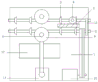
FIG. 1 is a front view of the present invention;
FIG. 2 is a schematic view of the transmission mechanism of the present invention;
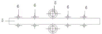
FIG. 3 is a schematic view of the construction of the delivery roll of the present invention.
Figure 4 is a schematic representation of the spindle of the present invention.
Detailed Description
The following describes the embodiments in further detail with reference to the accompanying drawings. The following examples are only for illustrating the technical solutions of the present invention more clearly, and the protection scope of the present invention is not limited thereby.
In one embodiment shown in fig. 1 to 4, a V-groove cutting apparatus includes: the box 1, drive mechanism, cutting mechanism, first actuating mechanism 13 and second actuating mechanism 14, drive mechanism, cutting mechanism and actuating mechanism fix respectively in box 1 inboardly, drive mechanism include two upper and lower parallel arrangement's pivot 2, pivot 2 links to each other with first actuating mechanism 13, every coaxial a plurality of first bevel gear 3 that evenly set up in pivot 2, and every first bevel gear 3 meshing connects second bevel gear 4, second bevel gear 4 is used for transmission product 5 along 2 length direction movements in pivot 2, two the line both sides of going on of pivot 2 set up cutting device respectively for from upper and lower both sides cutting product 5, cutting device links to each other with second actuating mechanism 14, and the downside of product 5 sets up a plurality of transfer rollers 6, transfer roller 6 sets up with pivot 2 perpendicularly.
The second bevel gear 4 is coaxially connected with an auxiliary shaft 7, and one side of the auxiliary shaft 7 is rotatably connected to the side wall of the box body 1.
The cutting device comprises a main shaft 8, two sides of the main shaft 8 are rotatably connected to the side wall of the box body 1, V-shaped milling cutters 9 and compression wheels 10 are arranged on the main shaft 8 at intervals, the compression wheels 10 are respectively arranged close to two sides of the product 5, and the V-shaped milling cutters 9 respectively cut one third of the upper thickness and the lower thickness of the product 5; the product 5 is compressed by the compression wheel 10, and the product 5 is conveniently cut by the V-shaped milling cutter 9.
Two rotating shafts 2 which are arranged in parallel up and down are connected through a synchronous belt 11, and the rotating shafts 2 are connected with a first driving mechanism 13.
The main shafts 8 of the cutting device are connected through a synchronous belt 11, and the main shafts 8 are connected with a second driving mechanism 14.
And the two ends of the rotating shaft 2 are rotatably connected to the side wall of the box body 1.
Set up the discharge gate on the 1 lateral wall of box of keeping away from hold-in range 11 one side in pivot 2, the discharge gate direction is parallel with pivot 2, set up the feed inlet on the lateral wall of hold-in range 11 end, the feed inlet direction is perpendicular with pivot 2.
The box body 1 is also internally provided with a dust suction mechanism 12, and the dust suction mechanism 12 is arranged at the lower side of the transmission mechanism and used for adsorbing dust in the cutting process.
The invention starts the first and the second driving motors, then transmits the torque and the direction through the transmission of the rotating shaft, the belt transmission and the bevel gear transmission, and can ensure the stable forward movement of the plate through the conveying roller between the two rotating shafts of the product plate.
The above description is only a preferred embodiment of the present invention, and it should be noted that, for those skilled in the art, several modifications and variations can be made without departing from the technical principle of the present invention, and these modifications and variations should also be regarded as the protection scope of the present invention.
Claims (8)
1. A V-groove cutting device, comprising: the box, drive mechanism, cutting mechanism, first actuating mechanism and second actuating mechanism, drive mechanism, cutting mechanism and actuating mechanism fix respectively in the box inboardly, drive mechanism include two upper and lower parallel arrangement's pivot, the pivot links to each other with first actuating mechanism, every coaxial a plurality of first bevel gears that evenly set up in the pivot, and every first bevel gear meshing connects second bevel gear, second bevel gear is used for the transmission product to move along pivot length direction, two the line-feeding both sides of pivot set up cutting device respectively for from upper and lower both sides cutting product, cutting device links to each other with second actuating mechanism, and the downside of product sets up a plurality of transfer rollers, the transfer roller sets up with the pivot perpendicularly.
2. The V-groove cutting device according to claim 1, wherein the second bevel gear is coaxially connected to an auxiliary shaft, and one side of the auxiliary shaft is rotatably connected to a side wall of the case.
3. The V-groove cutting device according to claim 1, wherein the cutting device comprises a main shaft, both sides of the main shaft are rotatably connected to the side walls of the box body, V-shaped milling cutters and pinch rollers are arranged on the main shaft at intervals, the pinch rollers are respectively arranged close to both sides of the product, and the V-shaped milling cutters respectively cut one third of the upper and lower thickness of the product.
4. The V-groove cutting device according to claim 1, wherein two rotating shafts of the transmission mechanism, which are arranged in parallel up and down, are connected through a timing belt, and the rotating shafts are connected with the first driving mechanism.
5. The V-groove cutting device according to claim 3, wherein the spindles of the cutting device are connected by a timing belt, and the spindles are connected to the second driving mechanism.
6. The V-groove cutting device according to claim 1, wherein both ends of the rotation shaft are rotatably connected to the side wall of the case.
7. The V-shaped groove cutting device according to claim 1, wherein a discharge port is arranged on the side wall of the box body on the side of the rotating shaft far away from the synchronous belt, the direction of the discharge port is parallel to the rotating shaft, a feed port is arranged on the side wall of the end of the synchronous belt, and the direction of the feed port is vertical to the rotating shaft.
8. The V-groove cutting device according to claim 1, wherein a dust suction mechanism is further provided in the case, the dust suction mechanism being provided at a lower side of the transmission mechanism.
Priority Applications (1)
| Application Number | Priority Date | Filing Date | Title |
|---|---|---|---|
| CN202011508267.3A CN112720640A (en) | 2020-12-18 | 2020-12-18 | V-shaped groove cutting device |
Applications Claiming Priority (1)
| Application Number | Priority Date | Filing Date | Title |
|---|---|---|---|
| CN202011508267.3A CN112720640A (en) | 2020-12-18 | 2020-12-18 | V-shaped groove cutting device |
Publications (1)
| Publication Number | Publication Date |
|---|---|
| CN112720640A true CN112720640A (en) | 2021-04-30 |
Family
ID=75603253
Family Applications (1)
| Application Number | Title | Priority Date | Filing Date |
|---|---|---|---|
| CN202011508267.3A Pending CN112720640A (en) | 2020-12-18 | 2020-12-18 | V-shaped groove cutting device |
Country Status (1)
| Country | Link |
|---|---|
| CN (1) | CN112720640A (en) |
Cited By (1)
| Publication number | Priority date | Publication date | Assignee | Title |
|---|---|---|---|---|
| CN114872112A (en) * | 2022-06-10 | 2022-08-09 | 安徽信息工程学院 | Mainboard cutting device for computer production |
Citations (5)
| Publication number | Priority date | Publication date | Assignee | Title |
|---|---|---|---|---|
| KR20170002240A (en) * | 2015-06-29 | 2017-01-06 | 주식회사 코스믹대영 | Plane setting apparatus and method of setting the V groove machine |
| CN207013792U (en) * | 2017-03-21 | 2018-02-16 | 惠州市纵胜电子材料有限公司 | A kind of dise knife wafer separator compacting wheel |
| CN208896189U (en) * | 2018-09-30 | 2019-05-24 | 杭州九州环保科技有限公司 | A kind of V cutting mill of adjustable wiring board cutting thickness |
| CN111730663A (en) * | 2020-07-21 | 2020-10-02 | 惠州市成盅机电设备有限公司 | A bidirectional V-CUT device |
| CN211842224U (en) * | 2019-11-15 | 2020-11-03 | 福州科之扬电子有限公司 | Shearing mechanism is used in processing of anti-exposure LED-PCB module |
-
2020
- 2020-12-18 CN CN202011508267.3A patent/CN112720640A/en active Pending
Patent Citations (5)
| Publication number | Priority date | Publication date | Assignee | Title |
|---|---|---|---|---|
| KR20170002240A (en) * | 2015-06-29 | 2017-01-06 | 주식회사 코스믹대영 | Plane setting apparatus and method of setting the V groove machine |
| CN207013792U (en) * | 2017-03-21 | 2018-02-16 | 惠州市纵胜电子材料有限公司 | A kind of dise knife wafer separator compacting wheel |
| CN208896189U (en) * | 2018-09-30 | 2019-05-24 | 杭州九州环保科技有限公司 | A kind of V cutting mill of adjustable wiring board cutting thickness |
| CN211842224U (en) * | 2019-11-15 | 2020-11-03 | 福州科之扬电子有限公司 | Shearing mechanism is used in processing of anti-exposure LED-PCB module |
| CN111730663A (en) * | 2020-07-21 | 2020-10-02 | 惠州市成盅机电设备有限公司 | A bidirectional V-CUT device |
Cited By (2)
| Publication number | Priority date | Publication date | Assignee | Title |
|---|---|---|---|---|
| CN114872112A (en) * | 2022-06-10 | 2022-08-09 | 安徽信息工程学院 | Mainboard cutting device for computer production |
| CN114872112B (en) * | 2022-06-10 | 2024-05-10 | 安徽信息工程学院 | Mainboard cutting device for computer production |
Similar Documents
| Publication | Publication Date | Title |
|---|---|---|
| CN111452129B (en) | Cardboard processing fly-cutting device | |
| CN222568524U (en) | Veneer reeling machine for aluminum veneer production | |
| CN207943625U (en) | A kind of paper feed mechanism of flat-press flat-die cutting machine | |
| CN112008786A (en) | A shape cutting device of preapring for an unfavorable turn of events for corrugated container board | |
| CN216634512U (en) | Automatic cutting and back wrapping mechanism of gluing machine | |
| CN105151860A (en) | High-speed splitting double-shaft cycled winding mechanism | |
| CN216300493U (en) | Energy-saving plastic bag lithography apparatus | |
| CN214769285U (en) | Automatic cutting equipment suitable for different steel products | |
| CN117428827A (en) | Battery foil slitting equipment and method with iron removal structure | |
| CN109775016B (en) | Paper feeding and cutting device for sugar paper | |
| CN213381786U (en) | Paper tube production and processing device | |
| CN221736343U (en) | A slitting thin knife paper separator | |
| CN210998891U (en) | Speed-adjustable corrugated board transverse cutting device | |
| CN212445511U (en) | Automatic feeding device of die-cutting machine | |
| CN222589946U (en) | A resin synthetic tile forming resin plate cutting device | |
| CN223507342U (en) | Liftable single-channel belt feeding device | |
| CN221775390U (en) | A roller-free carton slot printing machine for reducing carton cracking | |
| CN218664628U (en) | Material pulling and cutting machine | |
| CN212400455U (en) | Multifunctional transverse cutting machine for corrugated carton production | |
| CN224210667U (en) | Cutting machine is used in cigarette case processing | |
| CN216180855U (en) | Calender cutting positioning device is used in conveyer belt production | |
| CN220844038U (en) | Processing feeding mechanism | |
| CN222644846U (en) | A square wood multi-blade saw | |
| CN216001830U (en) | Printing device for carton surface | |
| CN222986490U (en) | Automatic feeding and discharging wire drawing machine for large plates |
Legal Events
| Date | Code | Title | Description |
|---|---|---|---|
| PB01 | Publication | ||
| PB01 | Publication | ||
| SE01 | Entry into force of request for substantive examination | ||
| SE01 | Entry into force of request for substantive examination | ||
| RJ01 | Rejection of invention patent application after publication | ||
| RJ01 | Rejection of invention patent application after publication |
Application publication date: 20210430 |