CN214109779U - Intelligent processing progress monitoring system for metal cutting - Google Patents
Intelligent processing progress monitoring system for metal cutting Download PDFInfo
- Publication number
- CN214109779U CN214109779U CN202022673804.1U CN202022673804U CN214109779U CN 214109779 U CN214109779 U CN 214109779U CN 202022673804 U CN202022673804 U CN 202022673804U CN 214109779 U CN214109779 U CN 214109779U
- Authority
- CN
- China
- Prior art keywords
- cutting
- lateral wall
- metal
- fixed mounting
- side wall
- Prior art date
- Legal status (The legal status is an assumption and is not a legal conclusion. Google has not performed a legal analysis and makes no representation as to the accuracy of the status listed.)
- Active
Links
Images


Abstract
The utility model belongs to the technical field of metal cutting processing technique and specifically relates to a metal cutting processing is with processing progress intelligent monitoring system, including the fixing base, the lower lateral wall four corners of fixing base is all fixed with the supporting leg, the upper lateral wall center department of fixing base has seted up the guide way, the inner chamber of guide way is equipped with the cutting bed, the lower lateral wall of guide way has seted up the spout, the lower lateral wall fixed mounting of cutting bed with the slide rail of spout looks adaptation, the preceding lateral wall of cutting bed is equipped with drive arrangement, the cutting bed, the preceding lateral wall fixed mounting of fixing base has the PLC controller, lower lateral wall one side fixed mounting of cutting bed has the mounting panel; compared with the prior art, the utility model discloses avoided traditional cutting at the metal man-hour, need just can be to the cutting of the different angles of metal through the angle of adjustment cutting metal, not only waste time and energy, the position of frequently adjusting the metal has increased the problem of the probability of metal damage moreover.
Description
Technical Field
The utility model relates to a metal cutting processing technology field especially relates to a metal cutting processing is with processing progress intelligent monitoring system.
Background
Metal cutting is a process of cutting excess material from a workpiece with a tool to obtain a part having a desired shape, dimensional accuracy, surface quality, and the like. Three conditions are required for realizing the cutting process, namely relative motion, namely cutting motion, is required between the workpiece and the cutter; the cutter material must have certain cutting performance; the tool must have the appropriate geometrical parameters, i.e. cutting angle, etc. The metal cutting process is performed by a machine tool or a hand tool, and the main methods include turning, milling, planing, grinding, drilling, boring, gear machining, scribing, sawing, filing, scraping, grinding, reaming, tapping, threading and the like. Although the forms of the cutting tool are various, the cutting tool has a common phenomenon and law in many aspects, and the phenomenon and the law are common bases for learning various cutting machining methods.
When metal is cut and processed traditionally, need just can be to the cutting of the different angles of metal through the angle of adjustment cutting metal, not only waste time and energy, frequently adjust the position of metal moreover and also increased the probability that the metal damaged.
SUMMERY OF THE UTILITY MODEL
The utility model aims at solving the shortcoming that exists among the prior art, and the intelligent monitoring system of processing progress for the metal cutting processing who provides.
In order to achieve the above purpose, the utility model adopts the following technical scheme:
the intelligent processing progress monitoring system for metal cutting processing comprises a fixed seat, wherein supporting legs are fixedly mounted at four corners of the lower side wall of the fixed seat, a guide groove is formed in the center of the upper side wall of the fixed seat, a cutting table is arranged in an inner cavity of the guide groove, a sliding groove is formed in the lower side wall of the guide groove, a sliding rail matched with the sliding groove is fixedly mounted on the lower side wall of the cutting table, a driving device is arranged on the front side wall of the cutting table, a PLC (programmable logic controller) is fixedly mounted on the front side wall of the fixed seat, a mounting plate is fixedly mounted on one side of the lower side wall of the cutting table, a displacement sensor is fixedly mounted at the center of one side, close to the fixed seat, and is electrically connected with the PLC, a top plate is arranged above the fixed seat, and stand columns are fixedly mounted at four corners of the lower side wall of the top plate, the upright post is fixedly connected with the fixed seat, both sides of the lower side wall of the top plate are fixedly provided with side plates, a motor-driven lead screw is rotatably arranged between two groups of side plates, the outer side of the lead screw is slidably provided with an adjusting seat, the lower side wall of the adjusting seat is fixedly provided with a first connecting plate, the center of the lower side wall of the first connecting plate is rotatably provided with a rotating shaft, the outer side of the rotating shaft is provided with an adjusting device, the lower side wall of the rotating shaft is fixedly provided with a second connecting plate, both sides of the lower side wall of the second connecting plate are fixedly provided with hoisting plates, the opposite sides of the two groups of hoisting plates are rotatably provided with rotating plates, the center of the lower side wall of the second connecting plate is rotatably provided with a hydraulic rod, the output end of the hydraulic rod is rotatably connected with the front side of the lower side wall of the rotating plate, and four corners of the upper side wall of the rotating plate are rotatably provided with telescopic rods, the outside cover of telescopic link is equipped with the telescopic link, the telescopic link is kept away from the one end of rotor plate with the second connecting plate rotates to be connected, the last lateral wall fixed mounting of rotor plate has inclination sensor, inclination sensor with the hydraulic stem all with PLC controller electric connection, the below of rotor plate is equipped with the cutting seat, the cutting seat with fixed mounting has electric telescopic handle between the rotor plate, electric telescopic handle with PLC controller electric connection, the inner chamber of cutting seat rotates installs motor drive's cutting sword.
Preferably, the driving device comprises a rack, the rack is fixedly installed on the front side wall of the cutting table, a first stepping motor is fixedly installed on the left side of the front side wall of the fixing seat, a gear is fixedly installed at the output end of the first stepping motor, a through hole matched with the gear is formed in the left side of the front side wall of the fixing seat, the gear penetrates through the through hole and extends to the inner cavity of the guide groove, the gear is meshed with the rack and is connected, and the first stepping motor is electrically connected with the PLC,
preferably, adjusting device includes the worm wheel, worm wheel fixed mounting in the outside of pivot, the lower lateral wall fixed mounting of first connecting plate has second step motor, second step motor with PLC controller electric connection, the output fixed mounting of second step motor have with the worm that the worm wheel meshing is connected, the installation tray is rotated in the outside of worm, the tray with first connecting plate fixed connection.
Preferably, two sets of symmetry fixed mounting of the last lateral wall of fixing base have the baffle of founding, the both sides top symmetry fixed mounting of cutting bed has the baffle, the baffle is located found the top of baffle.
Preferably, the outer side of the adjusting seat is slidably provided with a guide rod, and two ends of the guide rod are respectively connected with the two groups of side plates in a rotating manner.
Preferably, the two sides of the rotating plate are symmetrically and fixedly provided with guide blocks, and the opposite side walls of the two groups of hoisting plates are provided with arc-shaped guide rails matched with the guide blocks.
The utility model provides a pair of process progress intelligent monitoring system for metal cutting, beneficial effect lies in:
1. through setting up displacement sensor, first step motor and PLC controller for when first step motor drove the metal removal cutting of placing on cutting bed and the cutting bed, displacement sensor can real-time detection mounting panel and the fixing base between the interval, and transmit to the PLC controller, make the PLC controller can judge the progress that the metal was cut according to the size of cutting bed displacement, and then control opening of first step motor and stop, realize the accurate cutting of advancing to the metal.
2. Through setting up arc guide rail, hydraulic stem and inclination sensor for inclination that inclination sensor can real-time detection rotor plate, and transmit to the PLC controller, and control hydraulic stem start-up work, make the hydraulic stem pull the rotor plate and rotate, and then rotate the cutting sword to required inclination, in order to satisfy the cutting to the different angles of metal, compare with prior art, the utility model discloses avoided traditional cutting man-hour at the metal, need just can be to the cutting of the different angles of metal through the angle of adjustment cutting metal, not only waste time and energy, frequently adjust the problem that the position of metal has increased the probability of metal damage moreover.
Drawings
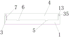
FIG. 1 is a front view of an intelligent monitoring system for monitoring the machining progress of metal cutting machining according to the present invention;
fig. 2 is a side view of a fixing seat structure of an intelligent processing progress monitoring system for metal cutting processing provided by the present invention;
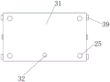
fig. 3 is a top view of a structure of a rotating plate of the intelligent processing progress monitoring system for metal cutting processing according to the present invention;
fig. 4 is the utility model provides a metal cutting is with processing progress intelligent monitoring system's hoist and mount plate structure side view.
In the figure: the cutting machine comprises a fixed seat 1, supporting legs 2, a guide groove 3, a cutting table 4, a sliding groove 5, a sliding rail 6, a rack 7, a first stepping motor 8, a through hole 9, a gear 10, a mounting plate 11, a displacement sensor 12, a baffle 13, an upright post 14, a top plate 15, a side plate 16, a screw rod 17, a guide rod 18, an adjusting seat 19, a rotating shaft 20, a first connecting plate 21, a second stepping motor 22, a worm wheel 23, a support block 24, an expansion rod 25, a spring 26, a worm 27, a second connecting plate 28, a hoisting plate 29, an arc-shaped guide rail 30, a rotating plate 31, a hydraulic rod 32, a cutting seat 33, a cutting knife 34, a vertical baffle 35, an inclination angle sensor 36, a PLC (programmable logic controller) 37, an electric expansion rod 38 and a guide block 39.
Detailed Description
The technical solutions in the embodiments of the present invention will be described clearly and completely with reference to the accompanying drawings in the embodiments of the present invention, and it is obvious that the described embodiments are only some embodiments of the present invention, not all embodiments.
Referring to fig. 1-4, an intelligent monitoring system for metal cutting process, comprising a fixed base 1, supporting legs 2 are fixedly mounted at four corners of a lower side wall of the fixed base 1, a guide groove 3 is formed in the center of an upper side wall of the fixed base 1, a cutting table 4 is arranged in an inner cavity of the guide groove 3, a sliding groove 5 is formed in the lower side wall of the guide groove 3, a sliding rail 6 matched with the sliding groove 5 is fixedly mounted on the lower side wall of the cutting table 4, a driving device is arranged on a front side wall of the cutting table 4, the driving device comprises a rack 7, the rack 7 is fixedly mounted on the front side wall of the cutting table 4, a first stepping motor 8 is fixedly mounted on the left side of the front side wall of the fixed base 1, a gear 10 is fixedly mounted on an output end of the first stepping motor 8, a through hole 9 matched with the gear 10 is formed in the left side of the front side wall of the fixed base 1, and the gear 10 extends to the inner cavity of the guide groove 3 through the through hole 9, gear 10 is connected with the meshing of rack 7, first step motor 8 and PLC controller 37 electric connection, and the top of cutting bed 4 is used for placing the metal of treating the cutting, and first step motor 8 is used for driving gear 10 to rotate at start-up during operation, and gear 10 is used for driving when rotating and drives cutting bed 4 through rack 7 and at the inner chamber side-to-side movement of guide way 3, and then drives the removal to cutting panel to the control of panel cutting progress is realized.
A cutting table 4, a PLC controller 37 is fixedly installed on the front side wall of a fixed seat 1, an installation plate 11 is fixedly installed on one side of the lower side wall of the cutting table 4, a displacement sensor 12 is fixedly installed at the center of one side of the installation plate 11 close to the fixed seat 1, the displacement sensor 12 is electrically connected with the PLC controller 37, a top plate 15 is arranged above the fixed seat 1, stand columns 14 are fixedly installed at four corners of the lower side wall of the top plate 15, the stand columns 14 are fixedly connected with the fixed seat 1, side plates 16 are fixedly installed at two sides of the lower side wall of the top plate 15, a motor-driven lead screw 17 is rotatably installed between the two sets of side plates 16, an adjusting seat 19 is slidably installed on the outer side of the lead screw 17, a first connecting plate 21 is fixedly installed on the lower side wall of the adjusting seat 19, a rotating shaft 20 is rotatably installed at the center of the lower side wall of the first connecting plate 21, an adjusting device is arranged on the outer side of the rotating shaft 20, the adjusting device comprises a worm wheel 23, the worm wheel 23 is fixedly installed on the outer side of the rotating shaft 20, the lower side wall of the first connecting plate 21 is fixedly provided with a second stepping motor 22, the second stepping motor 22 is electrically connected with the PLC controller 37, the output end of the second stepping motor 22 is fixedly provided with a worm 27 meshed with the worm wheel 23, the outer side of the worm 27 is rotatably provided with a support block 24, the support block 24 is fixedly connected with the first connecting plate 21, the displacement sensor 12 is used for detecting the distance between the mounting plate 11 and the fixing seat 1 in real time to judge the displacement of the cutting table 4 and transmit the displacement to the PLC controller 37 in real time, so that the metal cutting progress is judged, the screw rod 17 is used for driving the adjusting seat 19 to move back and forth when rotating, so that the front and back positions of the whole cutting are adjusted, the second stepping motor 22 is used for driving the worm wheel 23 and the rotating shaft 20 to rotate through the worm 27 when starting to work, and further adjustment of the cutting direction is realized.
A second connecting plate 28 is fixedly arranged on the lower side wall of the rotating shaft 20, hoisting plates 29 are fixedly arranged on both sides of the lower side wall of the second connecting plate 28, rotating plates 31 are rotatably arranged on opposite sides of the two groups of hoisting plates 29, a hydraulic rod 32 is rotatably arranged in the center of the lower side wall of the second connecting plate 28, the output end of the hydraulic rod 32 is rotatably connected with the front side of the lower side wall of the rotating plate 31, four corners of the upper side wall of the rotating plate 31 are rotatably provided with telescopic rods 25, the outer side of each telescopic rod 25 is sleeved with a telescopic rod 25, one end of each telescopic rod 25 far away from the rotating plate 31 is rotatably connected with the second connecting plate 28, an inclination angle sensor 36 is fixedly arranged on the upper side wall of the rotating plate 31, the inclination angle sensor 36 and the hydraulic rod 32 are electrically connected with a PLC 37, a cutting seat 33 is arranged below the rotating plate 31, an electric telescopic rod 38 is fixedly arranged between the cutting seat 33 and the rotating plate 31, and the electric telescopic rod 38 is electrically connected with the PLC 37, motor drive's cutting sword 34 is installed in the inner chamber rotation of cutting seat 33, hydraulic stem 32 is used for driving traction rotor plate 31 and rotates starting work hour, and then realize the regulation to cutting angle, it adds man-hour to have avoided traditional cutting at the metal, need just can be to the cutting of the different angles of metal through the angle of adjustment cutting metal, not only waste time and energy, and frequently adjust the position of metal and increased the probability that the metal damaged, inclination sensor 36 is used for the angle of rotor plate 31 to measure, and real-time transmission to cutting sword 34, so as to know cutting angle in real time, adjust seat 19 and drive cutting sword 34 up-and-down motion when being used for restarting, and then realize the regulation to cutting height.
Two sets of symmetry fixed mounting of the last lateral wall of fixing base 1 have found baffle 35, and the both sides top symmetry fixed mounting of cutting bed 4 has baffle 13, and baffle 13 is located the top of founding baffle 35, and baffle 13 and found baffle 35 and be used for stopping that the piece of metal cutting falls between rack 7 and gear 10, have reduced the wearing and tearing of rack 7 and gear 10.
The outer side of the adjusting seat 19 is slidably provided with a guide rod 18, two ends of the guide rod 18 are respectively rotatably connected with the two groups of side plates 16, and the guide rod 18 is used for guiding the movement of the adjusting seat 19.
The two sides of the rotating plate 31 are symmetrically and fixedly provided with guide blocks 39, the opposite side walls of the two groups of hoisting plates 29 are provided with arc-shaped guide rails 30 matched with the guide blocks 39, and the guide blocks 39 and the arc-shaped guide rails 30 are matched with each other to guide the rotation of the rotating plate 31.
The working principle is as follows: when the utility model is used, the cut metal is fixed above the cutting table 4, then the PLC controller 37 is used for controlling the motor driving the cutting knife 34, so that the cutting knife 34 continuously rotates, then the position, the angle and the depth of the metal material are cut as required, the PLC controller 37 is used for controlling the motor driving the screw rod 17, the second stepping motor 22, the hydraulic rod 32 and the adjusting seat 19 to start, the screw rod 17 is driven to rotate when the motor driving the screw rod 17 starts, the screw rod 17 drives the adjusting seat 19 to move back and forth when rotating, and further drives the cutting knife 34 to move back and forth, and further adjusts the cutting knife 34 to the corresponding position, the rotating plate 31 is driven to rotate when the hydraulic rod 32 starts, the inclination angle sensor 36 starts to work simultaneously, the angle of the inclination of the rotating plate 31 is measured in real time and transmitted to the PLC controller 37, after the hydraulic rod 32 drives the cutting knife 34 to rotate to a required inclination angle, the PLC controller 37 controls the hydraulic rod 32 to stop working, so that the cutting knife 34 is kept at a required angle, then the adjusting seat 19 is started, so that the adjusting seat 19 drives the cutting knife 34 to move up and down, the cutting knife 34 is adjusted to a required height, then the first stepping motor 8 is started, so that the first stepping motor 8 drives the gear 10 to rotate, the gear 10 drives the rack 7 and the cutting table 4 to move rightwards when rotating, so as to cut metal, the displacement sensor 12 can detect the distance between the mounting plate 11 and the fixing seat 1 in real time when cutting metal, and then judge the size of the cutting table 4 and the metal displacement, and transmit the size to the PLC controller 37 in real time, and further judge the cutting progress of the metal at the position.
The above, only be the concrete implementation of the preferred embodiment of the present invention, but the protection scope of the present invention is not limited thereto, and any person skilled in the art is in the technical scope of the present invention, according to the technical solution of the present invention and the utility model, the concept of which is equivalent to replace or change, should be covered within the protection scope of the present invention.
Claims (6)
1. The utility model provides a metal cutting is processing progress intelligent monitoring system for processing, includes fixing base (1), its characterized in that, the equal fixed mounting in lower lateral wall four corners of fixing base (1) has supporting leg (2), the last lateral wall center department of fixing base (1) has seted up guide way (3), the inner chamber of guide way (3) is equipped with cutting bed (4), spout (5) have been seted up to the lower lateral wall of guide way (3), the lower lateral wall fixed mounting of cutting bed (4) have with slide rail (6) of spout (5) looks adaptation, the preceding lateral wall of cutting bed (4) is equipped with drive arrangement, cutting bed (4), the preceding lateral wall fixed mounting of fixing base (1) has PLC controller (37), lower lateral wall one side fixed mounting of cutting bed (4) has mounting panel (11), mounting panel (11) are close to one side center department fixed mounting of fixing base (1) has displacement sensor (12), displacement sensor (12) with PLC controller (37) electric connection, the top of fixing base (1) is equipped with roof (15), the equal fixed mounting in lower lateral wall four corners of roof (15) has stand (14), stand (14) with fixing base (1) fixed connection, the equal fixed mounting in lower lateral wall both sides of roof (15) has curb plate (16), rotate between two sets of curb plate (16) and install motor drive's lead screw (17), the outside slidable mounting of lead screw (17) has regulation seat (19), the lower lateral wall fixed mounting of regulation seat (19) has first connecting plate (21), the lower lateral wall center department of first connecting plate (21) rotates and installs pivot (20), the outside of pivot (20) is equipped with adjusting device, the lower lateral wall fixed mounting of pivot (20) has second connecting plate (28), hoisting plates (29) are fixedly mounted on two sides of the lower side wall of the second connecting plate (28), rotating plates (31) are rotatably mounted on opposite sides of the two groups of hoisting plates (29), hydraulic rods (32) are rotatably mounted at the center of the lower side wall of the second connecting plate (28), the output ends of the hydraulic rods (32) are rotatably connected with the front sides of the lower side walls of the rotating plates (31), telescopic rods (25) are rotatably mounted at four corners of the upper side wall of the rotating plates (31), the outer side of each telescopic rod (25) is sleeved with a telescopic rod (25), one end, far away from the rotating plates (31), of each telescopic rod (25) is rotatably connected with the second connecting plate (28), an inclination angle sensor (36) is fixedly mounted on the upper side wall of the rotating plate (31), and the inclination angle sensor (36) and the hydraulic rods (32) are electrically connected with the PLC (37), the utility model discloses a motor drive's cutting tool, including rotor plate (31), cutting seat (33) is equipped with cutting seat (33) below rotor plate (31), cutting seat (33) with fixed mounting has electric telescopic handle (38) between rotor plate (31), electric telescopic handle (38) with PLC controller (37) electric connection, motor drive's cutting sword (34) are installed in the inner chamber rotation of cutting seat (33).
2. The intelligent processing progress monitoring system for metal cutting processing according to claim 1, wherein the driving device comprises a rack (7), the rack (7) is fixedly mounted on the front side wall of the cutting table (4), a first stepping motor (8) is fixedly mounted on the left side of the front side wall of the fixing seat (1), a gear (10) is fixedly mounted at the output end of the first stepping motor (8), a through hole (9) matched with the gear (10) is formed in the left side of the front side wall of the fixing seat (1), the gear (10) penetrates through the through hole (9) and extends to the inner cavity of the guide groove (3), the gear (10) is meshed with the rack (7) and is connected, and the first stepping motor (8) is electrically connected with the PLC (37).
3. The intelligent processing progress monitoring system for metal cutting processing as claimed in claim 1, wherein the adjusting device comprises a worm wheel (23), the worm wheel (23) is fixedly installed on the outer side of the rotating shaft (20), a second stepping motor (22) is fixedly installed on the lower side wall of the first connecting plate (21), the second stepping motor (22) is electrically connected with the PLC (37), a worm (27) meshed with the worm wheel (23) is fixedly installed on the output end of the second stepping motor (22), a support block (24) is rotatably installed on the outer side of the worm (27), and the support block (24) is fixedly connected with the first connecting plate (21).
4. The intelligent processing progress monitoring system for metal cutting processing according to claim 1, wherein two groups of vertical baffles (35) are symmetrically and fixedly mounted on the upper side wall of the fixed seat (1), baffles (13) are symmetrically and fixedly mounted on the tops of two sides of the cutting table (4), and the baffles (13) are located above the vertical baffles (35).
5. The intelligent monitoring system for the processing progress of metal cutting processing according to claim 1, characterized in that a guide rod (18) is slidably mounted on the outer side of the adjusting seat (19), and two ends of the guide rod (18) are respectively and rotatably connected with the two groups of side plates (16).
6. The intelligent processing progress monitoring system for metal cutting processing as recited in claim 1, wherein guide blocks (39) are symmetrically and fixedly mounted on both sides of the rotating plate (31), and arc-shaped guide rails (30) matched with the guide blocks (39) are respectively formed on opposite side walls of the two groups of hoisting plates (29).
Priority Applications (1)
| Application Number | Priority Date | Filing Date | Title |
|---|---|---|---|
| CN202022673804.1U CN214109779U (en) | 2020-11-18 | 2020-11-18 | Intelligent processing progress monitoring system for metal cutting |
Applications Claiming Priority (1)
| Application Number | Priority Date | Filing Date | Title |
|---|---|---|---|
| CN202022673804.1U CN214109779U (en) | 2020-11-18 | 2020-11-18 | Intelligent processing progress monitoring system for metal cutting |
Publications (1)
| Publication Number | Publication Date |
|---|---|
| CN214109779U true CN214109779U (en) | 2021-09-03 |
Family
ID=77505139
Family Applications (1)
| Application Number | Title | Priority Date | Filing Date |
|---|---|---|---|
| CN202022673804.1U Active CN214109779U (en) | 2020-11-18 | 2020-11-18 | Intelligent processing progress monitoring system for metal cutting |
Country Status (1)
| Country | Link |
|---|---|
| CN (1) | CN214109779U (en) |
Cited By (1)
| Publication number | Priority date | Publication date | Assignee | Title |
|---|---|---|---|---|
| CN113878168A (en) * | 2021-11-01 | 2022-01-04 | 平湖市华晟精密机械有限公司 | Aviation connector shell machining process and cutting machine for machining aviation connector shell |
-
2020
- 2020-11-18 CN CN202022673804.1U patent/CN214109779U/en active Active
Cited By (1)
| Publication number | Priority date | Publication date | Assignee | Title |
|---|---|---|---|---|
| CN113878168A (en) * | 2021-11-01 | 2022-01-04 | 平湖市华晟精密机械有限公司 | Aviation connector shell machining process and cutting machine for machining aviation connector shell |
Similar Documents
| Publication | Publication Date | Title |
|---|---|---|
| CN214109779U (en) | Intelligent processing progress monitoring system for metal cutting | |
| CN210188687U (en) | Sawing machine for steel processing | |
| CN214769062U (en) | Drilling equipment that multi-angle was adjusted | |
| CN201211696Y (en) | Hinge grooving mechanism of full-automatic wood door processor | |
| CN2526114Y (en) | Milling machine for internal hole key seat of large parts | |
| CN219310124U (en) | Radial drilling machine with drilling depth limiting mechanism | |
| CN200991783Y (en) | Fully-automatic single-axle round milling machine | |
| CN112317977A (en) | CNC automatic cutting device for plate production | |
| CN213615353U (en) | Multifunctional overturning platform | |
| CN215786893U (en) | Milling and drilling device for oil field base | |
| CN216176646U (en) | Turning mechanism for flange production | |
| CN211641650U (en) | Multifunctional vertical stone carving machine | |
| CN112207590A (en) | Multifunctional overturning platform | |
| CN2477335Y (en) | Woodworking engraving and milling machine | |
| CN220462397U (en) | Semi-automatic section bar cutting device | |
| CN220717947U (en) | Plate cutting saw for cutting metal plate | |
| CN219212275U (en) | Positioning mechanism for metal cutting machine tool | |
| CN214819828U (en) | Groove cutting device for groove cutting machine for dry-hanging side surface of stone | |
| CN215468341U (en) | Section end face milling device | |
| CN220718599U (en) | Auxiliary positioning structure of rocker arm drill | |
| CN212264505U (en) | Aluminum alloy jumbo size work piece rising head cutting machine convenient to operation | |
| CN219403905U (en) | Diamond adjustable structure for filament cutter | |
| CN219541876U (en) | Grooving machine with limiting function | |
| CN212705754U (en) | Automatic to high cutting water installation | |
| CN215279650U (en) | Water conservancy construction is with adjustable bar cutter who cuts off aircraft nose |
Legal Events
| Date | Code | Title | Description |
|---|---|---|---|
| GR01 | Patent grant | ||
| GR01 | Patent grant | ||
| TR01 | Transfer of patent right | ||
| TR01 | Transfer of patent right |
Effective date of registration: 20211109 Address after: 201500 No. 88, Tinghua Road, Tinglin Town, Jinshan District, Shanghai Patentee after: Riming computer accessories (Shanghai) Co.,Ltd. Address before: No.99, Bilin street, high tech Zone, Chengdu, Sichuan 610000 Patentee before: Sun Kui |