CN201211696Y - Hinge grooving mechanism of full-automatic wood door processor - Google Patents
Hinge grooving mechanism of full-automatic wood door processor Download PDFInfo
- Publication number
- CN201211696Y CN201211696Y CNU200820087402XU CN200820087402U CN201211696Y CN 201211696 Y CN201211696 Y CN 201211696Y CN U200820087402X U CNU200820087402X U CN U200820087402XU CN 200820087402 U CN200820087402 U CN 200820087402U CN 201211696 Y CN201211696 Y CN 201211696Y
- Authority
- CN
- China
- Prior art keywords
- hinge
- frame
- milling cutter
- support body
- automatic wood
- Prior art date
- Legal status (The legal status is an assumption and is not a legal conclusion. Google has not performed a legal analysis and makes no representation as to the accuracy of the status listed.)
- Expired - Fee Related
Links
Images


Abstract
The utility model relates to wood processing equipment, in particular to a hinge notching mechanism of a full automatic wooden door lock and a hinge processing machine, which comprises a framework (9) and is characterized in that a worktable controlled by an electric motor to move horizontally is matched with the framework in a sliding way; a wooden door is horizontally placed on the worktable; the lateral side of the framework is provided with a wooden door clamping device (4), and one side of the framework is provided with an electric milling cutter device (3) which can move relatively to the framework and has an adjustable pitching angle. Through the matching relation of a seat frame device as well as a horizontal shaft rotating structure, a screw-and-nut pair structure driven by an electric motor, and the worktable controlled by the electric motor to move horizontally, each electric motor is controlled by a computer chip, so that a milling cutter does elevating and pitching actions automatically according to a procedure, and simultaneously finishes notching to three hinge notches and can automatically process bevel hinge notches with obvious improvement for the processing efficiency and notching quality.
Description
Technical field
The utility model relates to wooden process equipment, particularly a kind of hinge fluting mechanism of full-automatic wood processing machine.
Background technology
In the production and processing of timber, need process the hole or the groove that are used to install lock or hinge, the processing method of present existing timber hole or groove, major part is used chisel and hand hammer by hand, and efficient is low, and is of poor quality.Chinese patent 200720002056.6 disclosed a kind of timber hinge groovers, realize mechanical slotting, but can only open one by one, need manual operation, operating efficiency and automaticity can not be satisfactory, the hinge groove of existing many doors need be processed into the inclined-plane in addition, does not find to process automatically the equipment of inclined-plane hinge groove at present as yet.
The utility model content
The purpose of this utility model is the hinge fluting mechanism of a kind of full-automatic wood processing machine of design, high efficiency, and can process inclined-plane hinge groove automatically.
In order to achieve the above object, the utility model is by the following technical solutions:
The hinge fluting mechanism of full-automatic wood processing machine, comprise frame, it is characterized in that the workbench and the frame that are moved horizontally by Electric Machine Control are slidingly matched, timber lies on the workbench, the side of frame is equipped with the timber clamping device, at the Electric milling cutter device that side installation can be moved relative to frame, the angle of pitch is adjustable of frame.
Described Electric milling cutter device is installed on the stand apparatus, stand apparatus comprise with frame length to parallel crossbeam, with the support body that crossbeam flexibly connects, the quantity of Electric milling cutter device is three of left, center, right; The cutter motor seat top and the cutter motor that are loaded on the mounting crossbeam are horizontal sliding matching structure.
The support body of described mounting is rotatably assorted with the trunnion axis that is fixed in frame, the mounting support body bottom of the Electric milling cutter device in the middle of being positioned at is connected with bolt and nut is secondary, and wherein nut and frame are fixed, and rocking handle is equipped with in the screw rod outer end, middle part serial connection shaft coupling, the pitch rotation structure of formation mounting.
On the mounting support body of the Electric milling cutter device in the middle of above-mentioned being positioned at the motor that rotating shaft makes progress is housed also, the extension of machine shaft is a screw rod, fixedlys connected with cutter motor seat base cross members with this screw rod nut engaged, makes the rotating drive cutter motor lifting of screw rod.
The crane of the mounting crossbeam bottom of the above-mentioned left and right Electric milling cutter device that is positioned at both sides respectively is equipped with balance cylinder, and the push rod of balance cylinder is fixedlyed connected with crane; The sidepiece of mounting support body is shaped on the longitudinal rail that the chute with the motor cabinet sidepiece is slidingly matched, and relative support body of motor cabinet or frame can be slided up and down.
Slide block structure is made on the top of described cutter motor seat, and guide rail structure is made in the cutter motor bottom, and has locking device.
The utility model stand apparatus by with the trunnion axis rotational structure, and by motor-driven bolt and nut auxiliary structure and the workbench matching relationship that moves horizontally by Electric Machine Control, each motor is controlled by computer chip, make the automatic follow procedure of milling cutter do lifting, pitching action, finish the system of opening simultaneously to three hinge grooves, and can process inclined-plane hinge groove automatically, solved the processing difficult problem of inclined-plane hinge groove, working (machining) efficiency, fluting quality and machining accuracy obviously improve, for full-automatic wood door lock, hinge processing machine have been realized automatic hinge fluting function.
Description of drawings
The utility model is described in further detail below in conjunction with drawings and Examples.
Fig. 1 is the front view of this full-automatic wood processing machine.
Fig. 2 is the right view of Fig. 1.
Fig. 3 is the lifting structure schematic diagram of this automatic hinge fluting mechanism Electric milling cutter device among Fig. 2.
Fig. 4 is the luffing structure schematic diagram of this automatic hinge fluting mechanism Electric milling cutter device among Fig. 2.
Fig. 5 is the balanced structure schematic diagram of this automatic hinge fluting mechanism Electric milling cutter device among Fig. 2.
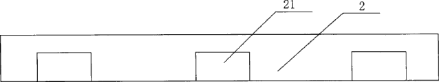
Fig. 6 opens the front view of system hinge face for timber.
The specific embodiment
With reference to Fig. 1, Fig. 2, this full-automatic wood door lock, hinge processing machine comprise frame 9, control the workbench 23 that moves horizontally by servomotor 1, workbench and frame 9 are slidingly matched, processed timber 2 lies on the workbench 23, a plurality of timber air clampers 4 are housed on the frame of workbench side, are exclusively used in out the Electric milling cutter device 3 of making the hinge groove with three of left, center, right can moving relative to frame, the angle of pitch is adjustable.Mounting lowering or hoisting gear 5 and elevation mount 8 are installed in the frame below of the Electric milling cutter device in the middle of being positioned at, and the bascule 6 of Electric milling cutter device is installed in the frame below that is positioned at two left and right Electric milling cutter devices.
With reference to Fig. 3, the Electric milling cutter device is installed on the stand apparatus 5, stand apparatus comprises long to parallel crossbeam 51 with frame 9, crossbeam 51 flexibly connects by angle steel 52 and support body 50, support body 50 installs horizontal support 58, horizontal support 58 and fulcrum 7 rotatable cooperate of horizontal fixed in frame 9 fronts make whole stand apparatus 5 frame 9 pitch rotation relatively.A servomotor 57 is installed in the bottom of support body 50, and its rotating shaft is connected up and with screw rod 55, and screw rod 55 tops are loaded on the top of support body 50 by bearing; Screw rod 55 and swivel nut 54 threaded engagement, swivel nut 54 is fixedlyed connected with angle steel 52 by pipe box 53, servomotor 57 drive screws 55 rotate swivel nut 54 are moved up and down, and swivel nut 54 drives angle steel 52 again and moves up and down, thus make on the crossbeam 51 Electric milling cutter device 3 relatively support body 50 do elevating movement.
Be loaded on aluminium alloy platform on the mounting crossbeam 51 and pull 37 end faces and be shaped on horizontal concrete chute, cutter motor seat bottom surface is shaped on above-mentioned horizontal concrete chute and cooperates slide rail 36, and the motor 31 that milling cutter 32 is housed can laterally be slided.The cutter motor seat is cooperated by chute slide rail pair 33,35 and constitutes, make cutter motor 31 can before and after slide and carry out the position adjustment, and can be by 34 lockings of bolt swing handle.
With reference to Fig. 4, the bottom of connecting rod 56 upper ends and support body 50 is fixed, lower end and screw rod 84 threaded engagement that have crank 81, and the tail end of screw rod 84 and nut 83 threaded engagement that are fixed in frame 9, the middle part of screw rod 84 is connected in series a Hooks coupling universal coupling 82.When carrying out skewed slot, needs open when system, shake crank 81 and make connecting rod 56 lower ends advance and retreat, because horizontal support 58 and fulcrum 7 rotatable cooperate of horizontal fixed in frame 9 fronts can rotate whole stand apparatus 5 around fulcrum 7, mill out inclined-plane hinge groove thereby drive cutter motor 31 as pitch rotation.
With reference to Fig. 5, because three Electric milling cutter device 3 weight in left, center, right are heavier, machine three Electric milling cutter device 3 easy run-off the straights and not in same level, influence machining accuracy in running so need also need to support in and arranged on left and right sides.Below left and right two Electric milling cutter devices 3, the mounting support body 50 that is installed on the horizontal support 58 is housed also, support body 50 and horizontal 7 rotatable cooperations of fulcrum, the sidepiece of support body 50 is shaped on longitudinal rail 63; Relative support body of motor cabinet or frame can be slided up and down.Respectively fall frame 61 in the bottom, relevant position of crossbeam 51 balance cylinder 65 is housed by the lifting motor seat, the medial surface of crane 61 is shaped on the chute 62 that is slidingly matched with above-mentioned longitudinal rail 63, balance cylinder 65 is installed on the link plate 64 that stretches out from support body 50, and the push rod of balance cylinder 65 is fixedlyed connected with crane 61.
The course of work: at first processed timber 2 is placed on the workbench 23, timber is fixedly clamped with air clamper 4; Startup servomotor 57 and balance cylinder 65 rise to the milling cutter top with three Electric milling cutter device 3 levels and timber hinge groove lower edge is touched, and the length of touching is the degree of depth of hinge groove; Start Electric milling cutter device 3 and microcomputer program controller, the servomotor 1 that can import predefined parameter, cyclelog is controlled each servomotor 57 and is milled out one earlier pod from bottom to top, servomotor 1 drives the move to left distance of a hinge length of timber, and each servomotor 57 mills out another road pod more from bottom to top; Servomotor 1 drives the reciprocal move left and right of timber, and each servomotor 57 progressively moves down, and will mill flat between the above-mentioned two vertical roads line by line and finishes the system of opening of three hinge grooves simultaneously, as shown in Figure 6.If need open the system surface groove, then shake crank 81 earlier and three Electric milling cutter devices 3 are in set the angle of pitch and get final product.
Claims (6)
1, the hinge of full-automatic wood processing machine fluting mechanism, comprise frame (9), it is characterized in that the workbench and the frame that are moved horizontally by Electric Machine Control are slidingly matched, timber lies on the workbench, the side of frame is equipped with timber clamping device (4), at the Electric milling cutter device (3) that side installation can be moved relative to frame, the angle of pitch is adjustable of frame.
2, according to the hinge of the described full-automatic wood processing machine of claim 1 fluting mechanism, it is characterized in that Electric milling cutter device (3) is installed on the stand apparatus (5), stand apparatus comprise with frame length to parallel crossbeam (51), with the support body (50) that crossbeam flexibly connects, the quantity of Electric milling cutter device is three of left, center, right; The cutter motor seat top and the cutter motor that are loaded on the mounting crossbeam are horizontal sliding matching structure.
3, according to the hinge of the described full-automatic wood processing machine of claim 2 fluting mechanism, the support body (50) that it is characterized in that described mounting is rotatably assorted with the trunnion axis (7) that is fixed in frame, the mounting support body bottom of the Electric milling cutter device in the middle of being positioned at is connected with bolt and nut is secondary, wherein nut (83) is fixing with frame (9), rocking handle (81) is equipped with in screw rod (84) outer end, middle part serial connection Hooks coupling universal coupling (82), the pitch rotation structure of formation mounting.
4, according to the hinge of claim 2 or 3 described full-automatic wood processing machines fluting mechanism, on the mounting support body (50) of the Electric milling cutter device in the middle of it is characterized in that being positioned at the motor (57) that rotating shaft makes progress is housed also, the extension of machine shaft is screw rod (55), fixedly connected with cutter motor seat base cross members with this screw rod nut engaged (54), make rotating drive cutter motor (31) lifting of screw rod.
5, according to the hinge of claim 1 or 2 described full-automatic wood processing machines fluting mechanism, the crane (61) of mounting crossbeam bottom that it is characterized in that being positioned at the left and right Electric milling cutter device of both sides respectively is equipped with balance cylinder (65), and the push rod of balance cylinder is fixedlyed connected with crane (61); The sidepiece of mounting support body (50) is shaped on the longitudinal rail (63) that the chute (61) with motor cabinet crane (61) sidepiece is slidingly matched, and relative support body of motor cabinet or frame can be slided up and down.
6, according to the hinge of the described full-automatic wood processing machine of claim 2 fluting mechanism, it is characterized in that cutter motor seat top makes slide block structure, guide rail structure is made in the cutter motor bottom, and has locking device.
Priority Applications (1)
| Application Number | Priority Date | Filing Date | Title |
|---|---|---|---|
| CNU200820087402XU CN201211696Y (en) | 2008-05-15 | 2008-05-15 | Hinge grooving mechanism of full-automatic wood door processor |
Applications Claiming Priority (1)
| Application Number | Priority Date | Filing Date | Title |
|---|---|---|---|
| CNU200820087402XU CN201211696Y (en) | 2008-05-15 | 2008-05-15 | Hinge grooving mechanism of full-automatic wood door processor |
Publications (1)
| Publication Number | Publication Date |
|---|---|
| CN201211696Y true CN201211696Y (en) | 2009-03-25 |
Family
ID=40495852
Family Applications (1)
| Application Number | Title | Priority Date | Filing Date |
|---|---|---|---|
| CNU200820087402XU Expired - Fee Related CN201211696Y (en) | 2008-05-15 | 2008-05-15 | Hinge grooving mechanism of full-automatic wood door processor |
Country Status (1)
| Country | Link |
|---|---|
| CN (1) | CN201211696Y (en) |
Cited By (6)
| Publication number | Priority date | Publication date | Assignee | Title |
|---|---|---|---|---|
| CN102490212A (en) * | 2011-12-20 | 2012-06-13 | 广州珠江钢琴集团股份有限公司 | Automatic drilling machine for piano hammer heads, multi-angle automatic drilling machine for piano hammer heads and automatic drilling system for piano hammer heads |
| CN103273543A (en) * | 2013-06-14 | 2013-09-04 | 广州珠江恺撒堡钢琴有限公司 | Automatic drilling machine for mediant hammer head in piano and drilling method |
| CN103659922A (en) * | 2012-09-21 | 2014-03-26 | 董金奎 | Batten fabricating device |
| CN106003266A (en) * | 2016-05-24 | 2016-10-12 | 苏州铨智动机械科技有限公司 | Processing technology for door frame waistline anti-cracking edge |
| CN108177212A (en) * | 2018-01-08 | 2018-06-19 | 海宁市豪派新材料科技有限公司 | A kind of timber installation hinge grooving |
| RU2755785C1 (en) * | 2019-09-05 | 2021-09-21 | Наньтун Юэтун Си Эн Си Эквипмент Ко., Лтд. | Control device for adjusting position of sawcut for hinge on machine |
-
2008
- 2008-05-15 CN CNU200820087402XU patent/CN201211696Y/en not_active Expired - Fee Related
Cited By (9)
| Publication number | Priority date | Publication date | Assignee | Title |
|---|---|---|---|---|
| CN102490212A (en) * | 2011-12-20 | 2012-06-13 | 广州珠江钢琴集团股份有限公司 | Automatic drilling machine for piano hammer heads, multi-angle automatic drilling machine for piano hammer heads and automatic drilling system for piano hammer heads |
| CN102490212B (en) * | 2011-12-20 | 2014-10-08 | 广州珠江钢琴集团股份有限公司 | Automatic drilling machine for piano hammer heads, multi-angle automatic drilling machine for piano hammer heads and automatic drilling system for piano hammer heads |
| CN103659922A (en) * | 2012-09-21 | 2014-03-26 | 董金奎 | Batten fabricating device |
| CN103273543A (en) * | 2013-06-14 | 2013-09-04 | 广州珠江恺撒堡钢琴有限公司 | Automatic drilling machine for mediant hammer head in piano and drilling method |
| CN103273543B (en) * | 2013-06-14 | 2015-03-18 | 广州珠江恺撒堡钢琴有限公司 | Automatic drilling machine for mediant hammer head in piano and drilling method |
| CN106003266A (en) * | 2016-05-24 | 2016-10-12 | 苏州铨智动机械科技有限公司 | Processing technology for door frame waistline anti-cracking edge |
| CN106003266B (en) * | 2016-05-24 | 2018-10-02 | 苏州铨木智能科技有限公司 | The anti-chip processing technology of waist in a kind of doorframe |
| CN108177212A (en) * | 2018-01-08 | 2018-06-19 | 海宁市豪派新材料科技有限公司 | A kind of timber installation hinge grooving |
| RU2755785C1 (en) * | 2019-09-05 | 2021-09-21 | Наньтун Юэтун Си Эн Си Эквипмент Ко., Лтд. | Control device for adjusting position of sawcut for hinge on machine |
Similar Documents
| Publication | Publication Date | Title |
|---|---|---|
| CN101279454B (en) | Full-automatic wood door lock, hinge groove and hole processor | |
| CN201189687Y (en) | Door keyhole and slot processing mechanism of full-automatic wood door processor | |
| CN201211696Y (en) | Hinge grooving mechanism of full-automatic wood door processor | |
| CN111085735B (en) | Processing device for non-involute variable thickness gear | |
| CN205969356U (en) | Novel floor four sides edge milling machines | |
| CN205341587U (en) | Servo follow -up forestock material mechanism | |
| CN209614418U (en) | Sheet end surface cutting equipment | |
| CN214109779U (en) | Intelligent processing progress monitoring system for metal cutting | |
| CN213615353U (en) | Multifunctional overturning platform | |
| CN211804032U (en) | Portable machining milling machine equipment | |
| CN112207590A (en) | Multifunctional overturning platform | |
| CN212682561U (en) | Metal processing milling machine | |
| CN218576325U (en) | Paperboard slotting equipment | |
| CN214394574U (en) | Horizontal puncher of regulation type plank | |
| CN2778502Y (en) | Upper horizontal cutter spindle carriage lifting device for four-side planing machine | |
| CN218192759U (en) | Steel plate edge milling device | |
| CN214079358U (en) | Multi-angle hinge drill | |
| CN215468341U (en) | Section end face milling device | |
| CN219520724U (en) | Multifunctional tapping machine | |
| CN209477360U (en) | A kind of aluminium door and window single head profiling machine | |
| CN216758959U (en) | CNC part turning device | |
| CN219255778U (en) | Paperboard cutting mechanism | |
| CN215510351U (en) | Plank beveling machine beveling position adjusting device | |
| CN219521474U (en) | Pitching adjusting device of ram of horizontal milling and boring machine | |
| CN220006270U (en) | Nut thread rolling machine with high shock absorption |
Legal Events
| Date | Code | Title | Description |
|---|---|---|---|
| C14 | Grant of patent or utility model | ||
| GR01 | Patent grant | ||
| CF01 | Termination of patent right due to non-payment of annual fee |
Granted publication date: 20090325 Termination date: 20150515 |
|
| EXPY | Termination of patent right or utility model |