CN214058694U - Kitchen waste recycling equipment - Google Patents
Kitchen waste recycling equipment Download PDFInfo
- Publication number
- CN214058694U CN214058694U CN202022468554.8U CN202022468554U CN214058694U CN 214058694 U CN214058694 U CN 214058694U CN 202022468554 U CN202022468554 U CN 202022468554U CN 214058694 U CN214058694 U CN 214058694U
- Authority
- CN
- China
- Prior art keywords
- box
- fixed
- motor
- broken
- crushing
- Prior art date
- Legal status (The legal status is an assumption and is not a legal conclusion. Google has not performed a legal analysis and makes no representation as to the accuracy of the status listed.)
- Active
Links
Images


Abstract
The utility model discloses a recovery plant of rubbish from cooking, the power distribution box comprises a box body, the top of box inner wall is fixed respectively and is equipped with first broken fill and the broken fill of second, and the top of first broken fill inner wall is rotated and is installed two matched with crushing rollers, and the top fixed mounting of box one side has two first motors of operation opposite direction, the output shaft of two first motors respectively with the one end fixed connection of two crushing roller rollers, the bottom fixed interlude of first broken fill is connected with first feed cylinder, the bottom of first broken fill is through two L type bracing piece fixedly connected with mounting boxes, the beneficial effects of the utility model are that: cooperate through the inside crushing roller of first broken hopper and the inside toper sword of first feed cylinder and grinding head and can smash stereoplasm rubbish, can smash soft rubbish through the inside broken blade of the broken hopper of second, and categorised crushing avoids harder thing to cause card machine phenomenon like bone, shell etc. increase of service life.
Description
Technical Field
The utility model relates to a recovery plant, in particular to recovery plant of rubbish from cooking belongs to refuse treatment technical field.
Background
The main components of the kitchen garbage comprise rice and flour food residues, vegetables, animal and vegetable oil, meat and bones and the like, and the kitchen garbage comprises starch, cellulose, protein, lipid and inorganic salt in chemical composition. The kitchen waste is mainly characterized by rich organic matter content, high water content and easy decay, the properties and smell of the kitchen waste can cause bad influence on environmental sanitation, and harmful substances such as pathogenic microorganisms, mycotoxin and the like can be easily grown. The nutrient components in the kitchen garbage are easy to be digested and utilized by animals, and are good feed raw materials.
Present rubbish from cooking recovery plant gets the processing mode to rubbish from cooking and beats the breakage with the tooth axle of high-speed rotation, grind and realize smashing, because rubbish kind is more, can't realize categorised crushing storage, be unfavorable for subsequent processing, often can meet harder thing like bone, shell etc. in smashing and cause the card machine phenomenon, it is not convenient enough to use, the life of motor has still been reduced simultaneously, and present rubbish from cooking recovery plant residue is for the general direct discharge of health, extravagant nutrient composition, can't store for a long time.
SUMMERY OF THE UTILITY MODEL
An object of the utility model is to provide a recovery plant of rubbish from cooking to solve the unable categorised crushing storage of the current rubbish from cooking recovery plant who proposes in the above-mentioned background art, cause the problem of card machine phenomenon and unable long-time storage easily.
In order to achieve the above object, the utility model provides a following technical scheme: a kitchen waste recycling device comprises a box body, wherein a first crushing hopper and a second crushing hopper are fixedly arranged at the top of the inner wall of the box body respectively, two matched crushing rollers are rotatably arranged at the top of the inner wall of the first crushing hopper, two first motors with opposite operation directions are fixedly arranged at the top of one side of the box body, output shafts of the two first motors are fixedly connected with one ends of two crushing roller shafts respectively, a first feed cylinder is fixedly and alternately connected to the bottom end of the first crushing hopper, a mounting box is fixedly connected to the bottom of the first crushing hopper through two L-shaped support rods, a double-shaft motor is fixedly arranged in the mounting box, a conical cutter is fixedly arranged on one output shaft of the double-shaft motor, a grinding head matched with the conical cutter is fixedly arranged in the first feed cylinder, and a rotating shaft is alternately arranged in the second crushing hopper, the avris on box top is fixed and is equipped with the second motor, the output shaft of second motor and the top fixed connection of pivot, the fixed broken blade that is equipped with of top of pivot, first breakage is fought and is fixed between the broken fill of second and is equipped with the baffle, the fixed type of falling V filter screen that is equipped with in bottom of box inner wall, the bottom of baffle and the middle part fixed connection on type of falling V filter screen top.
As an optimal technical scheme of the utility model, the bottom mounting interlude that the broken fill of second is connected with feed cylinder under the second, the middle part fixed mounting of pivot has the auger leaf with feed cylinder matched with under the second.
As an optimal technical scheme of the utility model, all fixed a plurality of stirring leaf that is equipped with the bottom of pivot on another output shaft of biax motor.
As a preferred technical scheme of the utility model, the bottom of box is equipped with the subassembly of supplying air, the subassembly of supplying air includes air heater and blast pipe, the fixed bottom that sets up at box another avris of air heater, the fixed bottom that sets up at the type of falling V filter screen of blast pipe, the air-out end of air heater passes through the fixed intercommunication of another avris of connecting pipe with the blast pipe, the top fixed mounting of blast pipe has the jet-propelled head of a plurality of.
As a preferred technical scheme of the utility model, the both sides side of box is equipped with exhaust subassembly, exhaust subassembly includes two blast pipes and two sleeve pipes, two the blast pipe is fixed respectively and alternates the middle part that sets up at box both sides side, two the sleeve pipe is threaded sleeve respectively and is established the one end at two blast pipes, two the inside both ends of sleeve pipe are fixed respectively and are equipped with two pairs and separate the net, and are every right it has the active carbon granule all to fill in the inside that separates the net.
As an optimal technical scheme of the utility model, the both sides side on box top articulates respectively has two case lids, the fixed flush mounting plate that is equipped with in middle part of box one side, flush mounting plate's surface is installed first motor control switch, biax motor control switch, the positive reverse switch of second motor and air heater control switch respectively, two first motor, biax motor, second motor and air heater are respectively through first motor control switch, biax motor control switch, the positive reverse switch of second motor and air heater control switch and external power supply electric connection.
Compared with the prior art, the beneficial effects of the utility model are that: the utility model relates to a recovery plant of surplus rubbish in kitchen, cooperate with the grinding head through the crushing roller inside the first crushing fill and the toper sword inside the first feed cylinder and can smash stereoplasm rubbish, can smash soft rubbish through the crushing blade inside the second crushing fill, categorised crushing avoids harder things such as bone, shell etc. to cause the card machine phenomenon, and the life is prolonged, can classify the storage to the rubbish after smashing through the baffle simultaneously, can classify the storage with profit and rubbish through the type of falling V filter screen, avoid mixing, the subsequent processing of being convenient for; can carry out the ventilation drying and disinfect the disinfection of disinfecting to the rubbish after smashing through supplying gas subassembly and exhaust subassembly cooperateing, the disinfection is more comprehensive thorough, has reached rapid draing, thoroughly sterile effect, is favorable to long-term storage.
Drawings
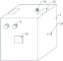
Fig. 1 is a schematic view of the overall structure of the present invention;
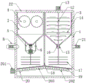
fig. 2 is a schematic sectional structure of the present invention;
FIG. 3 is an enlarged schematic view of part A of FIG. 2 according to the present invention;
fig. 4 is an enlarged schematic view of a portion B of fig. 2 according to the present invention.
In the figure: 1. a box body; 2. a first crushing hopper; 3. a second crushing hopper; 4. a crushing roller; 5. a first motor; 6. an L-shaped support bar; 7. mounting a box; 8. a double-shaft motor; 9. a conical cutter; 10. a first charging barrel; 11. a grinding head; 12. a rotating shaft; 13. a second motor; 14. crushing the blade; 15. a second charging barrel; 16. auger leaves; 17. stirring blades; 18. a partition plate; 19. an inverted V-shaped filter screen; 20. an air supply assembly; 201. a hot air blower; 202. an air supply pipe; 203. a gas showerhead; 21. an exhaust assembly; 211. an exhaust pipe; 212. a sleeve; 213. separating the net; 214. activated carbon particles; 22. a box cover; 23. a switch panel.
Detailed Description
The technical solutions in the embodiments of the present invention will be described clearly and completely with reference to the accompanying drawings in the embodiments of the present invention, and it is obvious that the described embodiments are only some embodiments of the present invention, not all embodiments. Based on the embodiments in the present invention, all other embodiments obtained by a person skilled in the art without creative work belong to the protection scope of the present invention.
Referring to fig. 1-4, the utility model provides a kitchen waste recycling device, which comprises a box body 1, wherein a first crushing bucket 2 and a second crushing bucket 3 are respectively fixed on the top of the inner wall of the box body 1, two matched crushing rollers 4 are rotatably installed on the top of the inner wall of the first crushing bucket 2, two first motors 5 with opposite operation directions are fixedly installed on the top of one side of the box body 1, the output shafts of the two first motors 5 are respectively fixedly connected with one ends of the roller shafts of the two crushing rollers 4, a first discharging barrel 10 is fixedly and alternately connected with the bottom end of the first crushing bucket 2, a mounting box 7 is fixedly connected with the bottom end of the first crushing bucket 2 through two L-shaped support rods 6, a double-shaft motor 8 is fixedly installed inside the mounting box 7, a conical cutter 9 is fixedly installed on one of the output shafts of the double-shaft motor 8, a grinding head 11 matched with the conical cutter 9 is fixedly installed inside the first discharging barrel 10, the inside of the broken 3 of fighting of second rotates and alternates and is equipped with pivot 12, the fixed second motor 13 that is equipped with of avris on 1 top of box, the output shaft of second motor 13 and the top fixed connection of pivot 12, the fixed a plurality of crushing blade 14 that is equipped with in top of pivot 12, cooperate through the crushing roller 4 of first broken 2 inside of fighting and the inside toper sword 9 of first feed cylinder 10 with grinding head 11 and can smash stereoplasm rubbish, can smash soft rubbish through the inside crushing blade 14 of the broken 3 of fighting of second, categorised crushing, avoid harder thing such as bone, shell etc. cause the card machine phenomenon, increase of service life, the fixed baffle 18 that is equipped with between first broken 2 of fighting and the broken 3 of second, the fixed inverted V filter screen 19 that is equipped with in bottom of box 1 inner wall, the bottom of baffle 18 and the middle part fixed connection on inverted V filter screen 19 tops.
Preferably, the bottom end of the second crushing hopper 3 is fixedly inserted and connected with a second discharging barrel 15, the middle part of the rotating shaft 12 is fixedly provided with an auger blade 16 matched with the second discharging barrel 15, the auger blade 16 is matched with the second discharging barrel 15 when the second motor 13 rotates forwards and backwards to facilitate discharging and material storage, a plurality of stirring blades 17 are fixedly arranged on the other output shaft of the double-shaft motor 8 and the bottom of the rotating shaft 12, the crushed garbage can be stirred and ventilated through the stirring blades 17 to improve the drying and sterilizing effects, the bottom of the box body 1 is provided with an air supply component 20, the air supply component 20 comprises an air heater 201 and an air supply pipe 202, the air heater 201 is fixedly arranged at the bottom of the other side of the box body 1, the air supply pipe 202 is fixedly arranged at the bottom of the inverted V-shaped filter screen 19, the air outlet end of the air heater 201 is fixedly communicated with the other side of the air supply pipe 202 through a connecting pipe, the top end of the air supply pipe 202 is fixedly provided with a plurality of air injection heads 203, the air heater 201 generates hot air which is conveyed to the blast pipe 202 through the connecting pipe, and then the crushed garbage can be ventilated, dried and sterilized through the ejection of the plurality of air nozzles 203, the sterilization is more comprehensive and thorough, the effects of quick drying and thorough sterilization are achieved, the exhaust assembly 21 is arranged on the two sides of the box body 1, the exhaust assembly 21 comprises two exhaust pipes 211 and two sleeve pipes 212, the two exhaust pipes 211 are respectively and fixedly inserted and arranged in the middle of the two sides of the box body 1, the two sleeve pipes 212 are respectively sleeved at one end of the two exhaust pipes 211 in a threaded manner, two pairs of partition nets 213 are respectively and fixedly arranged at the two ends inside the two sleeve pipes 212, activated carbon particles 214 are filled in each pair of partition nets 213, the activated carbon particles 214 passing through the exhaust assembly 21 can adsorb peculiar smell and toxic gas, the surrounding air environment is ensured, the human health is ensured, two box covers 22 are respectively hinged on the two sides of the top end of the box body 1, the fixed flush mounting plate of switch panel 23 that is equipped with in middle part of 1 one side of box, first motor control switch is installed respectively to flush mounting plate 23's surface, biax motor control switch, second motor just reverse switch and air heater control switch, two first motors 5, biax motor 8, second motor 13 and air heater 201 are respectively through first motor control switch, biax motor control switch, second motor just reverse switch and air heater control switch and external power supply electric connection, be convenient for control whole equipment through flush mounting plate of switch 23, and is easy and simple to handle.
When the kitchen garbage recycling device is used, firstly, the whole device is installed at a proper position, when garbage is thrown away, classified throwing is carried out according to the garbage types, when hard garbage is thrown away, one box cover 22 is opened to throw the hard garbage into the first crushing hopper 2, two first motors 5 and two shaft motors 8 are simultaneously started through a switch panel 23, two crushing rollers 4 are driven to rotate through the two first motors 5 to carry out pre-crushing, then a conical cutter 9 is driven to be matched with a grinding head 11 in a first discharging barrel 10 through the two shaft motors 8 to carry out secondary grinding, the crushing effect is improved, the crushed hard garbage falls to the other side of the top end of an inverted V-shaped filter screen 19, when soft garbage is thrown into the second crushing hopper 3 through the other box cover 22, and a second motor 13 is started through the switch panel 23, the second motor 13 drives the rotating shaft 12 to rotate forwards, the crushing blade 14 can be driven to crush the soft garbage, classification crushing is carried out, the phenomenon of blocking due to harder objects such as bones and shells is avoided, the service life is prolonged, meanwhile, the auger blade 16 and the second lower charging barrel 15 are matched for storing materials, the second motor 13 rotates backwards after crushing is finished to drive the rotating shaft 12 to rotate backwards, the auger blade 16 and the second lower charging barrel 15 are matched for blanking, the crushed soft garbage falls to the side of the top end of the inverted V-shaped filter screen 19, the crushed garbage is separated through the inverted V-shaped filter screen 19, the crushed garbage can be classified and stored through the partition plate 18, oil water and the garbage can be classified and stored through the inverted V-shaped filter screen 19 to avoid mixing, subsequent treatment is facilitated, the box cover 22 is covered after crushing is finished, the hot air heater 201 is started through the switch panel 23, hot air generated by the hot air heater 201 is conveyed to the air supply pipe 202 through the connecting pipe, the garbage after being crushed can be ventilated, dried and sterilized through the ejection of the plurality of air nozzles 203, the sterilization is more comprehensive and thorough, the effects of quick drying and thorough sterilization are achieved, the long-term storage is facilitated, hot air carrying moisture can be discharged out of the box body 1 through the exhaust assembly 21, peculiar smell and toxic gas can be adsorbed through the activated carbon particles 214 of the exhaust assembly 21, the surrounding air environment is ensured, and the human health is guaranteed.
In the description of the present invention, it should be understood that the indicated orientation or positional relationship is based on the orientation or positional relationship shown in the drawings, and is only for convenience of description and simplification of description, and does not indicate or imply that the indicated device or element must have a particular orientation, be constructed and operated in a particular orientation, and thus should not be construed as limiting the present invention.
In the present invention, unless otherwise explicitly specified or limited, for example, it may be fixedly connected, detachably connected, or integrated; can be mechanically or electrically connected; they may be directly connected or indirectly connected through an intermediate medium, and may be connected through the inside of two elements or in an interaction relationship between two elements, unless otherwise specifically defined, and the specific meaning of the above terms in the present invention will be understood by those skilled in the art according to specific situations.
Although embodiments of the present invention have been shown and described, it will be appreciated by those skilled in the art that changes, modifications, substitutions and alterations can be made in these embodiments without departing from the principles and spirit of the invention, the scope of which is defined in the appended claims and their equivalents.
Claims (6)
1. The kitchen waste recycling device comprises a box body (1) and is characterized in that a first crushing hopper (2) and a second crushing hopper (3) are fixedly arranged at the top of the inner wall of the box body (1) respectively, two matched crushing rollers (4) are rotatably arranged at the top of the inner wall of the first crushing hopper (2), two first motors (5) with opposite operation directions are fixedly arranged at the top of one side of the box body (1), output shafts of the two first motors (5) are fixedly connected with one ends of roll shafts of the two crushing rollers (4) respectively, a first charging barrel (10) is fixedly and alternately connected at the bottom end of the first crushing hopper (2), a mounting box (7) is fixedly connected at the bottom of the first crushing hopper (2) through two L-shaped support rods (6), and a double-shaft motor (8) is fixedly arranged inside the mounting box (7), fixed mounting has toper sword (9) on one of them output shaft of biax motor (8), the fixed grinding head (11) that is equipped with and toper sword (9) matched with in inside of first feed cylinder (10) down, the inside rotation that the broken fill of second (3) alternates and is equipped with pivot (12), the fixed second motor (13) that is equipped with of avris on box (1) top, the output shaft of second motor (13) and the top fixed connection of pivot (12), the fixed broken blade (14) of a plurality of that are equipped with in top of pivot (12), fixed baffle (18) that are equipped with between the broken fill of first broken fill (2) and second (3), the fixed type filter screen that falls V (19) that is equipped with in bottom of box (1) inner wall, the bottom of baffle (18) and the middle part fixed connection on type filter screen (19) top of falling V.
2. The recycling apparatus of kitchen waste according to claim 1, characterized in that: the bottom fixed interlude of second broken fill (3) is connected with feed cylinder (15) under the second, the middle part fixed mounting of pivot (12) has feed cylinder (15) matched with auger leaf (16) under with the second.
3. The recycling apparatus of kitchen waste according to claim 1, characterized in that: and a plurality of stirring blades (17) are fixedly arranged on the other output shaft of the double-shaft motor (8) and the bottom of the rotating shaft (12).
4. The recycling apparatus of kitchen waste according to claim 1, characterized in that: the bottom of box (1) is equipped with air supply assembly (20), air supply assembly (20) include air heater (201) and blast pipe (202), air heater (201) fixed setting is in the bottom of box (1) another avris, blast pipe (202) are fixed to be set up in the bottom of type of falling V filter screen (19), the air-out end of air heater (201) passes through the fixed intercommunication of another avris of connecting pipe and blast pipe (202), the top fixed mounting of blast pipe (202) has a plurality of jet-propelled head (203).
5. The recycling apparatus of kitchen waste according to claim 1, characterized in that: the both sides side of box (1) is equipped with exhaust subassembly (21), exhaust subassembly (21) include two blast pipes (211) and two sleeve pipes (212), two blast pipe (211) are fixed respectively and are alternated the middle part that sets up at box (1) both sides side, two sleeve pipe (212) threaded sleeve respectively is established in the one end of two blast pipes (211), two the inside both ends of sleeve pipe (212) are fixed respectively and are equipped with two pairs and separate net (213), and is every right the inside that separates net (213) all is filled with activated carbon granule (214).
6. The recycling apparatus of kitchen waste according to claim 4, characterized in that: the utility model discloses a box, including box (1), air heater (201), box (1) top, the both sides side articulates respectively has two case lids (22), the fixed flush mounting plate of switch panel (23) that is equipped with in middle part of box (1) one side, first motor control switch, biax motor control switch, the positive reverse switch of second motor and air heater control switch are installed respectively to the surface of flush mounting plate of switch (23), two first motor (5), biax motor (8), second motor (13) and air heater (201) are respectively through first motor control switch, biax motor control switch, the positive reverse switch of second motor and air heater control switch and external power supply electric connection.
Priority Applications (1)
| Application Number | Priority Date | Filing Date | Title |
|---|---|---|---|
| CN202022468554.8U CN214058694U (en) | 2020-10-30 | 2020-10-30 | Kitchen waste recycling equipment |
Applications Claiming Priority (1)
| Application Number | Priority Date | Filing Date | Title |
|---|---|---|---|
| CN202022468554.8U CN214058694U (en) | 2020-10-30 | 2020-10-30 | Kitchen waste recycling equipment |
Publications (1)
| Publication Number | Publication Date |
|---|---|
| CN214058694U true CN214058694U (en) | 2021-08-27 |
Family
ID=77398934
Family Applications (1)
| Application Number | Title | Priority Date | Filing Date |
|---|---|---|---|
| CN202022468554.8U Active CN214058694U (en) | 2020-10-30 | 2020-10-30 | Kitchen waste recycling equipment |
Country Status (1)
| Country | Link |
|---|---|
| CN (1) | CN214058694U (en) |
-
2020
- 2020-10-30 CN CN202022468554.8U patent/CN214058694U/en active Active
Similar Documents
| Publication | Publication Date | Title |
|---|---|---|
| CN110314743B (en) | Organic garbage treatment device for environment-friendly cultivation | |
| KR102096205B1 (en) | Drying and sterilizing device for died stock | |
| CN108816417B (en) | Cattle feed processing device | |
| CN205435905U (en) | Commercial food and beverage garbage disposer | |
| CN214058694U (en) | Kitchen waste recycling equipment | |
| KR100267499B1 (en) | Method and apparatus for manufacturing forage using garbage | |
| CN210847113U (en) | Deodorization type kitchen garbage classification device | |
| CN210417807U (en) | Deodorant kitchen garbage bin with shredding function | |
| CN205797404U (en) | For contaminating the grinding barrel of epidemic disease food processor | |
| CN210876720U (en) | Kitchen waste treatment device | |
| CN213645342U (en) | Household kitchen waste processor | |
| CN211272626U (en) | A degassing unit for organic wet rubbish of kitchen cabinet | |
| CN115382882A (en) | Harmless treatment equipment for medical wastes | |
| CN212791245U (en) | Dustproof effectual food processingequipment | |
| JP2000000555A (en) | Apparatus for drying solid residue such as waste food or the like | |
| CN211686743U (en) | Garbage disposal environment-friendly device | |
| CN208066439U (en) | A kind of refuse disposal installation of New-type instant recycling | |
| CN211190989U (en) | Intelligent kitchen garbage screening equipment | |
| CN108339638A (en) | A kind of home-use rubbish apparatus for crushing and treating | |
| JP2002143709A (en) | Organic waste pulverization throwing device | |
| KR20070067843A (en) | Processing device of food wastes | |
| KR101314870B1 (en) | foodwaste reduced an apparatus | |
| CN112295477A (en) | Garbage recycling and decomposing system for recycling environmental resources | |
| CN219194918U (en) | Kitchen waste fermentation device | |
| CN218058959U (en) | Kitchen garbage microbial fermentation and exhaust-gas treatment integration equipment |
Legal Events
| Date | Code | Title | Description |
|---|---|---|---|
| GR01 | Patent grant | ||
| GR01 | Patent grant |