CN213539427U - Curtain wall glass convenient to install - Google Patents
Curtain wall glass convenient to install Download PDFInfo
- Publication number
- CN213539427U CN213539427U CN202022402066.7U CN202022402066U CN213539427U CN 213539427 U CN213539427 U CN 213539427U CN 202022402066 U CN202022402066 U CN 202022402066U CN 213539427 U CN213539427 U CN 213539427U
- Authority
- CN
- China
- Prior art keywords
- plate
- curtain wall
- install
- metal plate
- wall glass
- Prior art date
- Legal status (The legal status is an assumption and is not a legal conclusion. Google has not performed a legal analysis and makes no representation as to the accuracy of the status listed.)
- Active
Links
Images


Abstract
The utility model discloses curtain wall glass convenient to install, in particular to the technical field of curtain wall glass, which comprises a glass body, wherein installation mechanisms are arranged on two sides of the glass body; the mounting mechanism comprises a circular rib plate, a metal plate is arranged on the inner side of the circular rib plate and movably connected with the circular rib plate through a rotating shaft, a plate groove is formed in the metal plate, two sliding blocks are slidably connected to the inner part of the plate groove, a threaded rod is fixedly arranged at the inner end of each sliding block and is arranged on the inner side of the metal plate, and two L-shaped plates are arranged at the inner end of the metal plate. The utility model discloses a mounting structure can install fixedly to the curtain wall glass of different thickness, not only easy dismounting and can the demand of different building outer walls of adjusting position and inclination adaptation.
Description
Technical Field
The embodiment of the utility model provides a curtain wall glass technical field, concretely relates to curtain wall glass easy to assemble.
Background
The curtain wall glass of modern high-rise building adopts hollow glass which is formed by combining mirror glass and common glass and filling dry air or inert gas into an interlayer. The hollow glass has the advantages of sound insulation, heat insulation, frost prevention, moisture prevention, high wind pressure resistance and the like. It was measured that when the outdoor temperature was-10 deg.c, the temperature before the single-layer glass window was-2 deg.c, and the indoor temperature using the triple-layer hollow glass was 13 deg.c. In hot summer, the double-layer hollow glass can block 90% of solar radiation heat. The sunlight still can permeate the glass curtain wall, but the sunshine can not feel hot on the body mostly. The room using the hollow curtain wall glass can be warm in winter and cool in summer, and the living environment is greatly improved.
The prior art has the following defects: due to the fact that the thickness of the curtain wall glass is different, time and labor are wasted when high-altitude installation operation is carried out, and installation is inconvenient.
SUMMERY OF THE UTILITY MODEL
Therefore, the embodiment of the utility model provides a curtain wall glass easy to assemble can install fixedly to the curtain wall glass of different thickness through mounting structure, not only easy dismounting and can the different building outer walls of adjusting position and inclination adaptation demand to solve among the prior art because curtain wall glass's thickness is not different to be accompanied with and carries out high altitude installation operation and waste time and energy and lead to installing inconvenient problem.
In order to achieve the above object, the embodiment of the present invention provides the following technical solutions: the curtain wall glass convenient to mount comprises a glass body, wherein mounting mechanisms are arranged on two sides of the glass body;
the glass body comprises a glass body, and is characterized in that the installation mechanism comprises a circular rib plate, a metal plate is arranged on the inner side of the circular rib plate and movably connected with the circular rib plate through a rotating shaft, a plate groove is formed in the metal plate, two sliders are slidably connected to the inner portion of the plate groove, a threaded rod is fixedly arranged at the inner end of each slider, the threaded rod is arranged on the inner side of the metal plate, two L-shaped plates are arranged at the inner end of the metal plate, the threaded rod penetrates through the L-shaped plates, nuts are connected to the outer ends of the threaded rods in a threaded manner, the nuts are arranged on the inner sides of the L-shaped plates, a strip-shaped hole is formed in the outer side of each L-shaped plate, a strip-shaped hole penetrates.
Further, the top of slider is fixed and is equipped with the bracing piece, the spout has been seted up on the top of metal sheet, the top of bracing piece runs through the spout and extends to the metal sheet top.
Further, the fixed diaphragm that is equipped with in top of bracing piece, the inside threaded connection of diaphragm has the quantity to be two sets of bolt one, the bottom of bolt one extends into the inside of diaphragm and contacts with the top of metal sheet, two the both sides at the spout are established respectively to bolt one, bolt one and diaphragm threaded connection.
Further, the outer end of the supporting rod is connected with the inner wall of the sliding groove in a sliding mode.
Further, the glass body is fixedly connected with the sealing sleeve through adhesive.
Further, the strip-shaped hole is connected with the threaded rod in a sliding mode.
Further, the outer end of the sealing sleeve is in contact with the inner side of the metal plate.
Furthermore, a fixing plate is fixedly arranged on one side of the metal plate, the fixing plate is arranged on the inner side of the circular rib plate, a second bolt is connected to the inner portion of the fixing plate in a threaded mode, and the rear end of the second bolt penetrates through the fixing plate and contacts with the inner side of the circular rib plate.
The embodiment of the utility model provides a have following advantage:
the utility model moves the two slide blocks on one side of the glass body horizontally in the metal plate, the slide blocks drive the L-shaped plate to move horizontally together through the threaded rods, so that the two L-shaped plates are clamped at the outer end of the glass body to fix the glass body, the front and back positions of the glass body are convenient to adjust, the strip-shaped holes on the L-shaped plates can be adjusted to a proper position along the outer end of the sliding block, thereby driving the glass body to move up and down to realize the adjustment of the up-and-down position of the glass body, rotating the metal plate to drive the glass body to rotate to a proper angle by taking the rotating shaft as the center of a circle to realize the angle adjustment of the glass body, the installation mechanism can be used for installing and fixing curtain wall glass with different thicknesses, is convenient to disassemble and assemble, and can adjust the position and the inclination angle to meet the requirements of different building outer walls.
Drawings
In order to more clearly illustrate the embodiments of the present invention or the technical solutions in the prior art, the drawings used in the description of the embodiments or the prior art will be briefly described below. It should be apparent that the drawings in the following description are merely exemplary, and that other embodiments can be derived from the drawings provided by those of ordinary skill in the art without inventive effort.
The structure, ratio, size and the like shown in the present specification are only used for matching with the content disclosed in the specification, so as to be known and read by people familiar with the technology, and are not used for limiting the limit conditions which can be implemented by the present invention, so that the present invention has no technical essential significance, and any structure modification, ratio relationship change or size adjustment should still fall within the scope which can be covered by the technical content disclosed by the present invention without affecting the efficacy and the achievable purpose of the present invention.
Fig. 1 is a schematic view of an overall top-view structure provided by the present invention;
FIG. 2 is a schematic side view of the structure of the circular rib plate provided by the present invention;
fig. 3 is a schematic front view of a metal plate structure provided by the present invention;
fig. 4 is a schematic top view of a metal plate structure provided by the present invention;
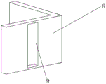
fig. 5 is a schematic structural view of an L-shaped plate provided by the present invention;
fig. 6 is a schematic front view of the overall structure provided by the present invention;
in the figure: 1 circular gusset, 2 pivot, 3 metal sheets, 4 board grooves, 5 sliders, 6 transverse plates, 7 bolt I, 8L-shaped plates, 9 strip-shaped holes, 10 nuts, 11 glass bodies, 12 sealing sleeves, 13 fixed plates, 14 bolt II, 15 threaded rods and 16 support rods.
Detailed Description
The present invention is described in terms of specific embodiments, and other advantages and benefits of the present invention will become apparent to those skilled in the art from the following disclosure. Based on the embodiments in the present invention, all other embodiments obtained by a person skilled in the art without creative work belong to the protection scope of the present invention.
Referring to the attached fig. 1-6 in the specification, the curtain wall glass convenient to mount in the embodiment includes a glass body 11, and mounting mechanisms are arranged on two sides of the glass body 11;
the mounting mechanism comprises a circular rib plate 1, a metal plate 3 is arranged on the inner side of the circular rib plate 1, the metal plate 3 is movably connected with the circular rib plate 1 through a rotating shaft 2, a plate groove 4 is arranged inside the metal plate 3, two sliding blocks 5 are connected inside the plate groove 4 in a sliding way, threaded rods 15 are fixedly arranged at the inner ends of the two sliding blocks 5, the threaded rod 15 is arranged on the inner side of the metal plate 3, two L-shaped plates 8 are arranged at the inner end of the metal plate 3, the threaded rod 15 penetrates through the L-shaped plate 8, the outer end of the threaded rod 15 is connected with a nut 10 in a threaded manner, the nut 10 is arranged on the inner side of the L-shaped plate 8, the outer side of the L-shaped plate 8 is provided with a strip-shaped hole 9, the strip-shaped hole 9 penetrates through the L-shaped plate 8, the threaded rod 15 runs through the strip-shaped hole 9, sealing sleeves 12 are arranged on two sides of the glass body 11, and the sealing sleeves 12 are arranged between the two L-shaped plates 8.
Further, the top of slider 5 is fixed and is equipped with bracing piece 16, the spout has been seted up on the top of metal sheet 3, the top of bracing piece 16 runs through the spout and extends to the top of metal sheet 3, and the slider 5 motion drives bracing piece 16 along the spout motion.
Further, the fixed diaphragm 6 that is equipped with in top of bracing piece 16, the inside threaded connection of diaphragm 6 has quantity to be two sets of bolt 7, the bottom of bolt 7 extends into the inside of diaphragm 6 and contacts with the top of metal sheet 3, two the both sides at the spout are established respectively to bolt 7, bolt 7 and diaphragm 6 threaded connection, thereby bracing piece 16 drives the motion of bolt 7 on diaphragm 6 and the diaphragm 6.
Furthermore, the outer end of the support rod 16 is connected with the inner wall of the sliding groove in a sliding manner, so that the position of the transverse plate 6 at the top end of the support rod 16 can be changed.
Further, the glass body 11 and the sealing sleeve 12 are fixedly connected through adhesive, and the glass body 11 is protected and sealed.
Further, the strip-shaped hole 9 is connected with the threaded rod 15 in a sliding mode, and therefore the upper position and the lower position of the L-shaped plate 8 are changed.
Further, the outer end of the sealing sleeve 12 is in contact with the inner side of the metal plate 3, and is tightly attached to the sealing sleeve 12.
Further, a fixing plate 13 is fixedly arranged on one side of the metal plate 3, the fixing plate 13 is arranged on the inner side of the circular rib plate 1, a second bolt 14 is connected to the inner portion of the fixing plate 13 in a threaded manner, the rear end of the second bolt 14 penetrates through the fixing plate 13 to be in contact with the inner side of the circular rib plate 1, and the glass body 11 is fixed and the inclination angle of the glass body is adjusted.
The implementation scenario is specifically as follows: firstly, a glass body 11 is arranged between two L-shaped plates 8, then the positions of two sliding blocks 5 on one side of the glass body 11 are horizontally moved in the metal plate 3, the sliding blocks 5 drive the L-shaped plates 8 to move together in the horizontal direction through threaded rods 15, meanwhile, the sliding blocks 5 move to drive supporting rods 16 to move along sliding grooves, so that a transverse plate 6 and bolts 7 on the transverse plate 6 are driven to move, when the two L-shaped plates 8 are clamped at the outer end of the glass body 11, the sliding blocks 5 are stopped to move, then the bolts 7 are screwed down to fix the transverse plate 6 and the top end of the metal plate 3, so that the supporting rods 16, the sliding blocks 5, the threaded rods 15 and the L-shaped plates 8 are fixed, meanwhile, the front and back positions of the glass body 11 are convenient to adjust, strip-shaped holes 9 on the L-shaped plates 8 can be adjusted to proper positions up and down, accomplish the fixed to L shaped plate 8 and glass body 11, and then realize adjusting glass body 11's upper and lower position, it uses pivot 2 to rotate suitable angle to rotate to the pivot to rotate metal sheet 3, screw bolt two 14 again, it is fixed to metal sheet 3 and glass body 11, the regulation of angle has been carried out to glass body 11, one side that will keep away from bolt two 14 is fixed on the building outer wall, can accomplish the installation of curtain wall glass, this installation mechanism can install fixedly to the curtain wall glass of different thickness, not only easy dismounting and can the different building outer wall's of adjusting position and inclination adaptation demand, this implementation mode has specifically solved among the prior art because the thickness of curtain wall glass is not different to be along with carrying out high altitude construction work and wastes time and energy and lead to the inconvenient problem of installation.
Although the invention has been described in detail with respect to the general description and the specific embodiments, it will be apparent to those skilled in the art that modifications and improvements can be made based on the invention. Therefore, such modifications and improvements are intended to be within the scope of the invention as claimed.
Claims (8)
1. The utility model provides a curtain wall glass easy to assemble, includes glass body (11), its characterized in that: mounting mechanisms are arranged on two sides of the glass body (11);
the installation mechanism comprises a circular rib plate (1), a metal plate (3) is arranged on the inner side of the circular rib plate (1), the metal plate (3) is movably connected with the circular rib plate (1) through a rotating shaft (2), a plate groove (4) is formed in the metal plate (3), two sliders (5) are slidably connected in the plate groove (4), a threaded rod (15) is fixedly arranged at the inner end of each slider (5), the threaded rod (15) is arranged on the inner side of the metal plate (3), two L-shaped plates (8) are arranged at the inner end of the metal plate (3), the threaded rod (15) penetrates through the L-shaped plates (8), a nut (10) is connected at the outer end of the threaded rod (15) through threads, the nut (10) is arranged on the inner side of the L-shaped plates (8), a strip-shaped hole (9) is formed in the outer side of the L-shaped plates (8), and the strip-shaped hole, the threaded rod (15) penetrates through the strip-shaped hole (9), sealing sleeves (12) are arranged on two sides of the glass body (11), and the sealing sleeves (12) are arranged between the two L-shaped plates (8).
2. The curtain wall glass convenient to install of claim 1, wherein: the top of slider (5) is fixed and is equipped with bracing piece (16), the spout has been seted up on the top of metal sheet (3), the spout extends to metal sheet (3) top is run through on the top of bracing piece (16).
3. The curtain wall glass convenient to install of claim 2, wherein: the fixed diaphragm (6) that is equipped with in top of bracing piece (16), the inside threaded connection of diaphragm (6) has quantity to be two sets of bolt (7), the bottom of bolt (7) extends into the inside of diaphragm (6) and contacts with the top of metal sheet (3), two the both sides at the spout are established respectively in bolt (7), bolt (7) and diaphragm (6) threaded connection.
4. The curtain wall glass convenient to install of claim 2, wherein: the outer end of the supporting rod (16) is connected with the inner wall of the sliding groove in a sliding mode.
5. The curtain wall glass convenient to install of claim 1, wherein: the glass body (11) is fixedly connected with the sealing sleeve (12) through adhesive.
6. The curtain wall glass convenient to install of claim 1, wherein: the strip-shaped holes (9) are connected with the threaded rods (15) in a sliding mode.
7. The curtain wall glass convenient to install of claim 1, wherein: the outer end of the sealing sleeve (12) is in contact with the inner side of the metal plate (3).
8. The curtain wall glass convenient to install of claim 1, wherein: a fixing plate (13) is fixedly arranged on one side of the metal plate (3), the fixing plate (13) is arranged on the inner side of the circular rib plate (1), a second bolt (14) is connected to the inner portion of the fixing plate (13) in a threaded mode, and the rear end of the second bolt (14) penetrates through the fixing plate (13) to be in contact with the inner side of the circular rib plate (1).
Priority Applications (1)
| Application Number | Priority Date | Filing Date | Title |
|---|---|---|---|
| CN202022402066.7U CN213539427U (en) | 2020-10-26 | 2020-10-26 | Curtain wall glass convenient to install |
Applications Claiming Priority (1)
| Application Number | Priority Date | Filing Date | Title |
|---|---|---|---|
| CN202022402066.7U CN213539427U (en) | 2020-10-26 | 2020-10-26 | Curtain wall glass convenient to install |
Publications (1)
| Publication Number | Publication Date |
|---|---|
| CN213539427U true CN213539427U (en) | 2021-06-25 |
Family
ID=76500136
Family Applications (1)
| Application Number | Title | Priority Date | Filing Date |
|---|---|---|---|
| CN202022402066.7U Active CN213539427U (en) | 2020-10-26 | 2020-10-26 | Curtain wall glass convenient to install |
Country Status (1)
| Country | Link |
|---|---|
| CN (1) | CN213539427U (en) |
-
2020
- 2020-10-26 CN CN202022402066.7U patent/CN213539427U/en active Active
Similar Documents
| Publication | Publication Date | Title |
|---|---|---|
| CN201826680U (en) | Dual hollow built-in sunshade energy-saving door and window system | |
| CN203891277U (en) | Steel structure solar glass curtain wall | |
| CN102536055A (en) | Pivoted sun-shade low-emissivity glass window | |
| CN213539427U (en) | Curtain wall glass convenient to install | |
| CN219431683U (en) | Aluminum alloy door and window heat insulation device | |
| WO2023226447A1 (en) | Environmentally friendly glass curtain wall structure | |
| CN201241584Y (en) | Thermal insulation heating window casing | |
| CN204593916U (en) | Flat panel solar heat collecting plate illumination angle adjustable support | |
| CN207079778U (en) | A kind of novel energy-saving construction curtain wall | |
| CN202073438U (en) | Unit window suitable for a curtain wall | |
| CN216588408U (en) | Energy-saving sun-shading blind window with direct light modification function | |
| CN220122832U (en) | Angle-adjustable trough type solar panel light-following device | |
| CN220273600U (en) | Wind-resistant photovoltaic module mounting bracket | |
| CN216041992U (en) | Adjustable green energy-saving building curtain wall | |
| CN216016783U (en) | Heat-insulation solar aluminum frame with adjustable supporting structure | |
| CN215255913U (en) | Adjustable green energy-saving building curtain wall | |
| CN204163297U (en) | A kind of solar energy heating heating structure | |
| CN217428052U (en) | Support for photovoltaic panel | |
| CN219365069U (en) | Windproof waterproof photovoltaic curtain wall component | |
| CN216197515U (en) | Building energy-saving sunshade green door and window structure | |
| CN204043217U (en) | Solar thermal collector and collecting plate thereof and be integrated with the window of this collecting plate | |
| CN213295192U (en) | Nano energy-saving glass for building | |
| CN216360954U (en) | Green building heat preservation sunshade system | |
| CN219808542U (en) | Double-layer curtain wall capable of adjusting temperature difference between inside and outside glass | |
| CN214462720U (en) | A sectional fixture for glass curtain wall construction |
Legal Events
| Date | Code | Title | Description |
|---|---|---|---|
| GR01 | Patent grant | ||
| GR01 | Patent grant |