CN213536268U - High slope material lifting machine - Google Patents
High slope material lifting machine Download PDFInfo
- Publication number
- CN213536268U CN213536268U CN202022417162.9U CN202022417162U CN213536268U CN 213536268 U CN213536268 U CN 213536268U CN 202022417162 U CN202022417162 U CN 202022417162U CN 213536268 U CN213536268 U CN 213536268U
- Authority
- CN
- China
- Prior art keywords
- hopper
- base
- high slope
- connecting piece
- slope material
- Prior art date
- Legal status (The legal status is an assumption and is not a legal conclusion. Google has not performed a legal analysis and makes no representation as to the accuracy of the status listed.)
- Expired - Fee Related
Links
- 239000000463 material Substances 0.000 title claims abstract description 27
- 230000007306 turnover Effects 0.000 claims description 13
- 238000009434 installation Methods 0.000 claims description 4
- 229910000831 Steel Inorganic materials 0.000 claims description 3
- 239000010959 steel Substances 0.000 claims description 3
- 238000010276 construction Methods 0.000 abstract description 7
- 239000007858 starting material Substances 0.000 description 2
- 230000009286 beneficial effect Effects 0.000 description 1
- 230000003139 buffering effect Effects 0.000 description 1
- 230000000694 effects Effects 0.000 description 1
- 238000000034 method Methods 0.000 description 1
- 238000004064 recycling Methods 0.000 description 1
- 238000004804 winding Methods 0.000 description 1
Images


Abstract
The utility model relates to a material transport technical field, more specifically say, relate to a high slope material hoist. Including the hopper dolly, slide rail and mounting bracket, the mounting bracket sets up on the side slope, slide rail and mounting bracket fixed connection, the hopper dolly includes the base, turning device and hopper, turning device sets up on the base, turning device upper portion and hopper bottom fixed connection, the base bottom is provided with the pulley, the base bottom is provided with the cylinder, the cylinder both sides are provided with motor and bearing frame respectively, the cylinder passes through driving shaft and motor and bearing frame hookup, the slide rail top is provided with the connecting block, be connected with wire rope on the cylinder, wire rope's the other end is fixed on the connecting block. The device promotes stability well, and is efficient, is showing the working strength who has alleviateed constructor's transport, has improved the construction security. The utility model discloses mainly use in the aspect of the high slope material lifting.
Description
Technical Field
The utility model relates to a material transport technical field, more specifically say, relate to a high slope material hoist.
Background
Traditional cutting high slope protection material transportation all needs the manpower to move, and the conveying efficiency is low, consumes huge manpower, and along with time, the increase in number of times of moving in addition, artifical inevitable can be because the amount of labour is too big produces tired sense, has accident such as tired type incident or manual operation error.
SUMMERY OF THE UTILITY MODEL
For overcoming the not enough of existence among the above-mentioned prior art, the utility model provides a high slope material lifting machine, the device adapt to various side slopes, and the lift process is steady, and work efficiency is high, has characteristics such as relative cost is lower, high efficiency, factor of safety height.
In order to solve the technical problem, the utility model discloses the technical scheme who takes does:
the utility model provides a high slope material lifting machine, includes hopper dolly, slide rail and mounting bracket, the mounting bracket sets up on the side slope, slide rail and mounting bracket fixed connection, the hopper dolly includes base, turning device and hopper, turning device sets up on the base, turning device upper portion and hopper bottom fixed connection, the base bottom is provided with the pulley, the base bottom is provided with the cylinder, the cylinder both sides are provided with motor and bearing frame respectively, the cylinder passes through driving shaft and motor and bearing frame hookup, the slide rail top is provided with the connecting block, be connected with wire rope on the cylinder, wire rope's the other end is fixed on the connecting block.
One side of the base is provided with a control box, and the control box is electrically connected with the motor.
And a baffle is arranged at the top of the rear end of the hopper.
The rear end of the hopper is provided with a handle.
The base is provided with a cushion block, and the cushion block is arranged at the position where the base is contacted with the hopper.
The mounting bracket comprises a positioning vertical rod and a transverse rod, the positioning vertical rod is symmetrically arranged at two ends of the transverse rod, and the transverse rod is fixedly connected with the positioning vertical rods at the two ends.
The turnover device is arranged at the front end of the base and comprises a first connecting piece and a second connecting piece, the first connecting piece is fixedly arranged on the base, the second connecting piece is fixedly arranged at the lower part of the hopper, and the first connecting piece and the second connecting piece are hinged through a high-strength bolt.
Compared with the prior art, the utility model discloses the beneficial effect who has does:
the installation frame is arranged, so that the device can adapt to the construction of side slopes with various gradients, the installation frame is convenient to erect, and the requirement of recycling is met; the arrangement of the pulleys enables the hopper trolley to stably run on the slide rails, so that the trolley can be better controlled; due to the arrangement of the turnover device, the unloading operation of constructors is met after the materials are transported to the side slope by the trolley, namely, the materials can be unloaded by turning over the hopper through the turnover device, and the hopper does not need to be manually carried; the combination of the roller and the motor enables the trolley to stably move upwards along the side slope, so that the material is lifted; the setting of cushion has reduced the collision of hopper with the base, has improved the life of product. The device promotes stability well, and is efficient, is showing the working strength who has alleviateed constructor's transport, has improved the construction security.
Drawings
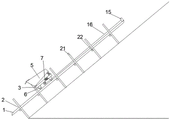
FIG. 1 is a schematic view of the construction of the present invention;
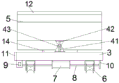
FIG. 2 is a side view of a part of a hopper car of the present invention;
FIG. 3 is a partial front view of the hopper car of the present invention;
FIG. 4 is a partial top view of the hopper car of the present invention;
FIG. 5 is a schematic view of the slide rail of the present invention;
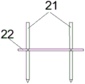
FIG. 6 is a schematic view of a part of the structure of the mounting rack of the present invention;
in the figure: the device comprises a sliding rail 1, a mounting frame 2, a positioning vertical rod 21, a transverse rod 22, a base 3, a turnover device 4, a first connecting piece 41, a second connecting piece 42, a high-strength bolt 43, a hopper 5, a pulley 6, a roller 7, a driving shaft 8, a motor 9, a bearing seat 10, a control box 11, a baffle 12, a handle 13, a cushion block 14, a connecting block 15 and a steel wire rope 16.
Detailed Description
The technical solutions in the embodiments of the present invention will be described clearly and completely with reference to the accompanying drawings in the embodiments of the present invention, and it is obvious that the described embodiments are only some embodiments of the present invention, not all embodiments. Based on the embodiments in the present invention, all other embodiments obtained by a person skilled in the art without creative work belong to the protection scope of the present invention.
As shown in fig. 1 to 6, a high slope material elevator comprises a hopper trolley, a slide rail 1 and a mounting rack 2, the mounting rack 2 is arranged on a slope, the slide rail 1 is fixedly connected with the mounting rack 2 in a binding manner, the hopper trolley comprises a base 3, a turnover device 4 and a hopper 5, the turnover device 4 is arranged on the base 3, the upper part of the turnover device 4 is fixedly connected with the bottom of the hopper 5, pulleys 6 are arranged at the bottom of the base 3, two pairs of pulleys 6 are symmetrically arranged, a roller 7 is arranged at the bottom of the base 3, a motor 9 and a bearing seat 10 are respectively arranged at two sides of the roller 7, the tops of the motor 9 and the bearing seat 10 are both fixedly connected with the base 3, the roller 7 is connected with the motor 9 and the bearing seat 10 through driving shafts 8 at two sides, the roller 7 is fixedly connected with the driving shafts 8, the driving shafts 8 are connected, the other end of the wire rope 16 is fixed on the connecting block 15. Set up mounting bracket 2 on the slope, the ligature of slide rail 1 is fixed on mounting bracket 2, and 6 interlocks of pulley of dolly are on slide rail 1, and starter motor 9, motor 9 pass through driving shaft 8 and drive cylinder 7 and rotate, and when cylinder 7 rotated, twine wire rope 16 on cylinder 7, because wire rope's the other end is fixed to be set up on connecting block 15, so the hopper dolly can be followed slide rail 1 and upwards removed.
Preferably, a control box 11 is arranged on one side of the base 3, the control box 11 is electrically connected with the motor 9, and the control box 11 can control the rotation direction and the rotation speed of the motor 9.
Preferably, a baffle 12 is arranged at the top of the rear end of the hopper 5, and the baffle 12 is arranged to prevent the materials from falling from the rear of the hopper 5 when the inclination angle is large.
Preferably, the rear end of the hopper 5 is provided with a handle 13, and a constructor can turn over the hopper through the handle 13 so as to unload materials.
Preferably, the base 3 is provided with a cushion block 14, the cushion block 14 is arranged at a position where the base 3 is contacted with the hopper 5, and the cushion block 14 is made of a buffering wear-resistant material.
Preferably, the mounting rack 2 comprises a positioning vertical rod 21 and a cross rod 22, the positioning vertical rod 21 is symmetrically arranged at two ends of the cross rod 22, the cross rod 22 is fixedly connected with the positioning vertical rod 21 at the two ends, and a conical pointed end is arranged at the bottom of the positioning vertical rod 21, so that the positioning vertical rod 21 can be firmly inserted into the side slope.
Preferably, the turnover device 4 is arranged at the front end of the base 3, the turnover device 4 comprises a first connecting piece 41 and a second connecting piece 42, the first connecting piece 41 is fixedly arranged on the base 3, the second connecting piece 42 is fixedly arranged at the lower part of the hopper 5, and the first connecting piece 41 and the second connecting piece 42 are hinged through a high-strength bolt 43.
During construction, erect mounting bracket 2 on the construction side slope, fix slide rail 1 ligature on mounting bracket 2, place the hopper dolly on slide rail 1, the pulley 6 and the interlock of slide rail 1 of dolly, the material is put into hopper 5, through control box 11 starter motor 9, motor 9 drives cylinder 7 and rotates, make 16 at the uniform velocity windings of wire rope on cylinder 7, reach the effect that promotes the hopper dolly, when the dolly removes to the construction height, operating personnel makes motor 9 stop work through control box 11, handheld 13 upset hoppers 5 of handle, unload through the material, the hopper dolly of controlling again falls to the starting point and feeds materials once more.
The above description has been made in detail only for the preferred embodiment of the present invention, but the present invention is not limited to the above embodiment, and various changes can be made without departing from the spirit of the present invention within the knowledge scope of those skilled in the art, and all such changes are intended to be encompassed by the present invention.
Claims (7)
1. The utility model provides a high slope material hoist which characterized in that: comprises a hopper trolley, a slide rail (1) and an installation rack (2), wherein the installation rack (2) is arranged on a side slope, the slide rail (1) is fixedly connected with the mounting rack (2), the hopper trolley comprises a base (3), a turnover device (4) and a hopper (5), the turnover device (4) is arranged on the base (3), the upper part of the turnover device (4) is fixedly connected with the bottom of the hopper (5), the bottom of the base (3) is provided with a pulley (6), the bottom of the base (3) is provided with a roller (7), a motor (9) and a bearing seat (10) are respectively arranged at two sides of the roller (7), the roller (7) is connected with a motor (9) and a bearing seat (10) through a driving shaft (8), the top of the sliding rail (1) is provided with a connecting block (15), the roller (7) is connected with a steel wire rope (16), and the other end of the steel wire rope (16) is fixed on the connecting block (15).
2. The high slope material hoist of claim 1, characterized in that: base (3) one side is provided with control box (11), control box (11) and motor (9) electric connection.
3. The high slope material hoist of claim 1, characterized in that: and a baffle (12) is arranged at the top of the rear end of the hopper (5).
4. The high slope material hoist of claim 1, characterized in that: and a handle (13) is arranged at the rear end of the hopper (5).
5. The high slope material hoist of claim 1, characterized in that: the hopper is characterized in that a cushion block (14) is arranged on the base (3), and the cushion block (14) is arranged at the position where the base (3) is in contact with the hopper (5).
6. The high slope material hoist of claim 1, characterized in that: the mounting rack (2) comprises a positioning vertical rod (21) and a transverse rod (22), the positioning vertical rod (21) is symmetrically arranged at two ends of the transverse rod (22), and the transverse rod (22) is fixedly connected with the positioning vertical rod (21) at the two ends.
7. The high slope material hoist of claim 1, characterized in that: turning device (4) set up the front position in base (3), turning device (4) include first connecting piece (41) and second connecting piece (42), first connecting piece (41) are fixed to be set up on base (3), second connecting piece (42) are fixed to be set up in hopper (5) lower part, first connecting piece (41) and second connecting piece (42) are articulated through high strength bolt (43).
Priority Applications (1)
| Application Number | Priority Date | Filing Date | Title |
|---|---|---|---|
| CN202022417162.9U CN213536268U (en) | 2020-10-27 | 2020-10-27 | High slope material lifting machine |
Applications Claiming Priority (1)
| Application Number | Priority Date | Filing Date | Title |
|---|---|---|---|
| CN202022417162.9U CN213536268U (en) | 2020-10-27 | 2020-10-27 | High slope material lifting machine |
Publications (1)
| Publication Number | Publication Date |
|---|---|
| CN213536268U true CN213536268U (en) | 2021-06-25 |
Family
ID=76500842
Family Applications (1)
| Application Number | Title | Priority Date | Filing Date |
|---|---|---|---|
| CN202022417162.9U Expired - Fee Related CN213536268U (en) | 2020-10-27 | 2020-10-27 | High slope material lifting machine |
Country Status (1)
| Country | Link |
|---|---|
| CN (1) | CN213536268U (en) |
Cited By (1)
| Publication number | Priority date | Publication date | Assignee | Title |
|---|---|---|---|---|
| CN115199043A (en) * | 2022-07-04 | 2022-10-18 | 广西交通职业技术学院 | Integrated device for on-site transporting and pouring of sand-free macroporous concrete |
-
2020
- 2020-10-27 CN CN202022417162.9U patent/CN213536268U/en not_active Expired - Fee Related
Cited By (1)
| Publication number | Priority date | Publication date | Assignee | Title |
|---|---|---|---|---|
| CN115199043A (en) * | 2022-07-04 | 2022-10-18 | 广西交通职业技术学院 | Integrated device for on-site transporting and pouring of sand-free macroporous concrete |
Similar Documents
| Publication | Publication Date | Title |
|---|---|---|
| CN108792634A (en) | A kind of classification box for material circulation apparatus for automatically loading | |
| CN107082291A (en) | A kind of feedbag entrucking palletizing apparatus and palletizing method, storage medium | |
| CN213536268U (en) | High slope material lifting machine | |
| US3945522A (en) | Apparatus for loading goods | |
| CN2871459Y (en) | Cantilever lump forming unit | |
| CN212768216U (en) | Floating belt conveyor | |
| CN210557297U (en) | Material elevator | |
| CN203033294U (en) | Container wood floor automatic material trimming and feeding conveying device | |
| CN205555556U (en) | Promote truck -loading facilities | |
| CN212173854U (en) | Automatic feeding device for alloy baking furnace | |
| CN209740233U (en) | Chain type lifting material pouring machine | |
| CN106629466A (en) | Rapid and convenient loading and unloading truck | |
| CN213568499U (en) | Movable loading and unloading elevator | |
| CN213504515U (en) | Portable sample groove device | |
| CN220519296U (en) | Lifting conveyor | |
| CN218909158U (en) | Simple grain unloading device | |
| CN216566499U (en) | Novel high-speed elevator | |
| CN212769655U (en) | Building engineering material conveyor | |
| CN110624837A (en) | Continuous vertical sorting system | |
| CN213325461U (en) | Two-way band conveyer of slope adjustable | |
| CN217025209U (en) | Continuous circulating elevator | |
| CN109760997A (en) | A kind of brick stacking machine receipts plate hoisting mechanism | |
| CN218433201U (en) | Conveying device for ALC (autoclaved lightweight concrete) board production | |
| CN220282531U (en) | Vehicle-mounted conveying device | |
| CN213445702U (en) | Double-car reciprocating type elevator |
Legal Events
| Date | Code | Title | Description |
|---|---|---|---|
| GR01 | Patent grant | ||
| GR01 | Patent grant | ||
| CF01 | Termination of patent right due to non-payment of annual fee |
Granted publication date: 20210625 |
|
| CF01 | Termination of patent right due to non-payment of annual fee |