CN213530343U - Stamping production integrated equipment - Google Patents
Stamping production integrated equipment Download PDFInfo
- Publication number
- CN213530343U CN213530343U CN202022543483.3U CN202022543483U CN213530343U CN 213530343 U CN213530343 U CN 213530343U CN 202022543483 U CN202022543483 U CN 202022543483U CN 213530343 U CN213530343 U CN 213530343U
- Authority
- CN
- China
- Prior art keywords
- stamping
- assembly
- sheet
- driving
- taking
- Prior art date
- Legal status (The legal status is an assumption and is not a legal conclusion. Google has not performed a legal analysis and makes no representation as to the accuracy of the status listed.)
- Active
Links
Images


Abstract
The utility model provides a stamping production integration device, which relates to the technical field of stamping machinery and comprises a material storage device, a positioning device, a material moving device and a control device; the storage device comprises an object stage; the positioning device comprises a first rack, a first material taking assembly and a correcting assembly, wherein the first material taking assembly is movably arranged on the first rack, the correcting assembly and the object stage are arranged at intervals along the moving direction of the first material taking assembly, the first material taking assembly is used for conveying a sheet material to be processed on the object stage to the correcting assembly, and the correcting assembly is used for positioning the sheet material to be processed; the material moving device comprises a second material taking assembly and a material moving driving mechanism; the material storage device, the positioning device and the material moving device are all electrically connected with the control device. Through this punching production integrated equipment, solved current punching equipment in the production process, artifical the participation too much leads to the great technical problem of intensity of labour.
Description
Technical Field
The utility model belongs to the technical field of the stamping machine technique and specifically relates to a stamping production integrated equipment is related to.
Background
In China, as a large manufacturing country, sheet metal part stamping is widely applied to various fields of national economy, and for example, stamping is performed in the industries of machinery, electrical appliances, light industry and the like. Stamping of sheet metal parts is an important component of transmission machining, and has the irreplaceable advantages of stable quality, low cost, simple and convenient stamping operation and the like.
In the production process of the sheet metal stamping process, a stamping press is one of the most common devices, and the stamping press mainly completes stamping forming work of sheet metal parts. And this production process generally puts into stamping press through the manual work sheet metal component of taking, and this mode can accurately place the sheet metal component in stamping die, but blowing and material taking process are participated in by the manual work mostly, and this greatly increased artificial intensity of labour.
SUMMERY OF THE UTILITY MODEL
An object of the utility model is to provide a stamping production integrated equipment to alleviate stamping equipment among the prior art in the production process, artifical the participation too much leads to the great technical problem of intensity of labour.
In a first aspect, an embodiment of the present invention provides a stamping production integrated equipment, including: storage device, positioner, move material device and controlling means.
The storing device comprises a carrying platform for placing a material pile to be processed.
The positioning device comprises a first rack, a first material taking assembly and a correcting assembly, wherein the first material taking assembly is movably arranged on the first rack, the correcting assembly and the object stage are arranged at intervals along the moving direction of the first material taking assembly, the first material taking assembly is used for conveying the sheet materials to be processed on the object stage to the correcting assembly, and the correcting assembly is used for positioning the sheet materials to be processed.
The material moving device comprises a second material taking assembly and a material moving driving mechanism in transmission connection with the second material taking assembly, and the second material taking assembly is used for conveying the sheet materials and/or stamping parts to be processed under the driving of the material moving driving mechanism.
The material storage device, the positioning device and the material moving device are electrically connected with the control device.
In an alternative embodiment, the magazine further comprises a lifting mechanism and a first sensor element.
The output end of the lifting mechanism is connected with the objective table and used for lifting the objective table.
The first sensing element is used for sensing the height position of the top sheet stock of the material pile on the object stage, the first sensing element and the lifting mechanism are both electrically connected with the control device, and the control device is used for controlling the lifting action of the lifting mechanism and keeping the top sheet stock of the material pile on the object stage at a preset height.
In an alternative embodiment, the stamping production integrated equipment further comprises a feeding device, and the feeding device comprises a track and a feeding trolley connected to the track in a sliding mode.
The feeding trolley comprises a trolley body used for placing a material pile to be processed, and a position avoiding hole used for the objective table to pass through is formed in the trolley body.
The feeding trolley runs along the track and can be arranged above the objective table, and the objective table can penetrate through the avoiding hole under the driving of the lifting mechanism and lift the material pile to be processed on the trolley body.
In an optional implementation mode, at least two groups of limiting assemblies are arranged on the vehicle body.
Each group of limiting assemblies comprises a pressing plate and vertical plates, the pressing plate is fixedly arranged on the upper surface of the trolley body, the vertical plates are vertically arranged on the pressing plate, and at least two vertical plates can limit the position of the two side surfaces of the material pile to be processed.
In an alternative embodiment, the installation position of the vertical plate on the pressure plate is adjustable and is used for adapting to the sheets to be processed with different sizes.
In an optional embodiment, the first sensing element is disposed on the vertical plate of at least one set of the limiting assemblies.
In an optional embodiment, the storage devices are two groups, and the two groups of storage devices are arranged at intervals along the extending direction of the track.
Every group storage device all corresponds and is provided with the pay-off dolly, positioner and move the material device.
In an optional embodiment, the first rack includes an upper rack, a lower rack, and an accommodating area, and the upper rack and the accommodating area are both located below the upper rack.
First material taking assembly sliding connection in upper support body.
The correction assembly is arranged on the lower layer frame body.
The objective table is arranged in the accommodating area, and a reserved space for enabling the feeding trolley to be erected on the objective table is arranged between the objective table and the upper shelf body.
In an alternative embodiment, the first take-off assembly is slidably coupled to the first frame.
The first material taking assembly comprises a material taking power element and a material taking clamp connected with the material taking power element in a transmission mode, and the material taking clamp can be close to or far away from the objective table under the driving of the material taking power element.
In an alternative embodiment, the correction assembly includes a base plate, a fixing block disposed on the base plate, a sliding block slidably connected to the base plate, and a positioning driving element for driving the sliding block to move.
The sliding block is driven by the positioning driving element, so that the distance between the sliding block and the fixed block can be matched with the size of a sheet to be processed.
In an optional embodiment, a sheet separating sensing element for sensing the number of sheets to be processed is arranged on the bottom plate, and the sheet separating sensing element is electrically connected with the control device.
In an alternative embodiment, the positioning device further comprises a magnetic distractor, which is mounted to the first frame.
The magnetic separator comprises a magnetic part, wherein the magnetic part is arranged facing the objective table and is used for magnetically separating sheet materials at the top end of the material pile on the objective table.
In an optional embodiment, the second material taking assembly comprises a material taking clamp and a stamping part taking clamp, and the material taking clamp and the stamping part taking clamp are arranged at intervals.
Move material actuating mechanism including driving horizontal actuating mechanism and vertical actuating mechanism, horizontal actuating mechanism is used for driving get piece material anchor clamps with get stamping workpiece anchor clamps synchronous motion in the horizontal direction, vertical actuating mechanism is used for driving get piece material anchor clamps with get stamping workpiece anchor clamps synchronous motion in the vertical direction.
The movement direction of the sheet taking clamp and the movement direction of the sheet taking clamp in the horizontal direction are the same as the movement direction of the first material taking assembly.
In an optional embodiment, the stamping production integrated equipment further comprises a material receiving device.
The receiving device comprises a discharging platform, and the two times of the distance between the sheet taking clamp and the stamping part taking clamp are matched with the distance between the object stage and the discharging platform.
In an optional embodiment, the material receiving device further comprises a second frame.
The discharging table adopts a belt type conveying assembly, and the belt type conveying assembly comprises a belt driving element, a plurality of belt pulleys pivoted to the second rack and a plurality of belts connected with the belt pulleys.
The front end of second frame is equipped with second sensing element, the rear end of second frame is equipped with third sensing element, second sensing element with third sensing element all is used for the response whether have the stamping workpiece on the belt.
The belt driving element, the second sensing element and the third sensing element are all electrically connected with the control device.
Has the advantages that:
the utility model provides a punching press production integrated equipment, the objective table is used for placing the material heap of waiting to process, because correction subassembly and objective table are laid along the direction of movement interval of first material subassembly of getting, under the effect of first material subassembly of getting, the first material subassembly of getting can replace the artifical sheet stock of waiting to process of taking on the objective table, and send this sheet stock of waiting to process to the correction subassembly, thereby treat through the correction subassembly and process the sheet stock and fix a position, in order to ensure that the sheet stock of waiting to process can be in the position that has predetermine before getting into punching press equipment, be used for ensuring the precision of punching press production process; and moreover, the second material taking assembly can convey the sheet materials and/or the stamping parts to be processed under the driving of the material moving driving mechanism.
According to the stamping production integration equipment, the material storage device, the positioning device, the material moving device and the control device are integrated together, the material storage device, the positioning device and the material moving device are controlled through the control device, the cooperative action among the material storage device, the positioning device and the material moving device is ensured, the machine replaces manpower to reduce the participation of the manpower, the labor intensity of the manpower is reduced, and the threat of the manual sheet material taking to operators is effectively reduced.
Drawings
In order to more clearly illustrate the embodiments of the present invention or the technical solutions in the prior art, the drawings used in the embodiments or the technical solutions in the prior art will be briefly described below, and it is obvious that the drawings in the following description are some embodiments of the present invention, and for those skilled in the art, other drawings can be obtained according to these drawings without creative efforts.
Fig. 1 is a schematic structural diagram of a stamping production integration apparatus provided in an embodiment of the present invention;
fig. 2 is a schematic structural view of a storage device and a track in the stamping production integration equipment provided by the embodiment of the present invention;
fig. 3 is a schematic structural view of a feeding trolley in the stamping production integrated equipment provided by the embodiment of the present invention;
fig. 4 is a schematic structural diagram of a positioning device in the integrated stamping and production equipment provided by an embodiment of the present invention;
fig. 5 is a schematic structural diagram of a material moving device in the integrated stamping and production equipment provided by the embodiment of the present invention;
fig. 6 is a schematic structural diagram of a material receiving device in the integrated equipment for stamping production provided by the embodiment of the present invention.
Icon:
100-a storage device; 110-an object stage; 120-a lifting mechanism;
200-a positioning device; 210-a first rack; 220-a first take-off assembly; 230-a correction component; 240-magnetic separator; 231-a base plate; 232-fixed block; 233-a slider; 234-distraction sensing elements;
300-a material moving device; 310-a sheet taking clamp; 320-taking a stamping part clamp; 330-lateral drive mechanism; 340-vertical drive mechanism;
400-a control device;
500-a feeding device; 510-a track; 520-a feeding trolley; 521-a vehicle body; 522-a press plate; 523-vertical plate; 5211-avoiding holes;
600-a material receiving device; 610-a discharge table; 620-a second rack; 630-a second inductive element; 640-a third inductive element;
700-punching device.
Detailed Description
In order to make the objects, technical solutions and advantages of the embodiments of the present invention clearer, the embodiments of the present invention will be clearly and completely described below with reference to the accompanying drawings in the embodiments of the present invention, and it is obvious that the described embodiments are some, but not all, embodiments of the present invention. The components of embodiments of the present invention, as generally described and illustrated in the figures herein, may be arranged and designed in a wide variety of different configurations.
Thus, the following detailed description of the embodiments of the present invention, presented in the accompanying drawings, is not intended to limit the scope of the invention, as claimed, but is merely representative of selected embodiments of the invention. Based on the embodiments in the present invention, all other embodiments obtained by a person skilled in the art without creative efforts belong to the protection scope of the present invention.
It should be noted that: like reference numbers and letters refer to like items in the following figures, and thus, once an item is defined in one figure, it need not be further defined and explained in subsequent figures.
In the description of the present invention, it should be noted that the terms "center", "upper", "lower", "left", "right", "vertical", "horizontal", "inner", "outer", and the like indicate the position or positional relationship based on the position or positional relationship shown in the drawings, or the position or positional relationship which is usually placed when the product of the present invention is used, and are only for convenience of description and simplification of the description, but do not indicate or imply that the device or element referred to must have a specific position, be constructed and operated in a specific orientation, and thus, should not be construed as limiting the present invention. Furthermore, the terms "first," "second," "third," and the like are used solely to distinguish one from another and are not to be construed as indicating or implying relative importance.
Furthermore, the terms "horizontal", "vertical" and the like do not imply that the components are required to be absolutely horizontal or pendant, but rather may be slightly inclined. For example, "horizontal" merely means that the direction is more horizontal than "vertical" and does not mean that the structure must be perfectly horizontal, but may be slightly inclined.
In the description of the present invention, it should also be noted that, unless otherwise explicitly specified or limited, the terms "disposed," "mounted," "connected," and "connected" are to be construed broadly, e.g., as meaning either a fixed connection, a removable connection, or an integral connection; can be mechanically or electrically connected; they may be connected directly or indirectly through intervening media, or they may be interconnected between two elements. The specific meaning of the above terms in the present invention can be understood in specific cases to those skilled in the art.
Some embodiments of the present invention will be described in detail below with reference to the accompanying drawings. The embodiments described below and the features of the embodiments can be combined with each other without conflict.
Examples
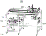
The embodiment provides a stamping production integrated device, as shown in fig. 1, fig. 2 and fig. 4, the production integrated device includes a storage device 100, a positioning device 200, a material moving device 300 and a control device 400; the storing device 100 comprises a carrier 110 for placing a stack to be processed; the positioning device 200 comprises a first rack 210, a first material taking assembly 220 and a correcting assembly 230, wherein the first material taking assembly 220 is movably arranged on the first rack 210, the correcting assembly 230 and the object stage 110 are arranged at intervals along the moving direction of the first material taking assembly 220, the first material taking assembly 220 is used for conveying the sheet to be processed on the object stage 110 to the correcting assembly 230, and the correcting assembly 230 is used for positioning the sheet to be processed; the material moving device 300 comprises a second material taking assembly and a material moving driving mechanism in transmission connection with the second material taking assembly, and the second material taking assembly is used for conveying the sheet materials to be processed and the stamping parts under the driving of the material moving driving mechanism; the storing device 100, the positioning device 200 and the material moving device 300 are all electrically connected with the control device 400.
In the stamping production integration equipment provided by the embodiment, the object stage 110 is used for placing a material pile to be processed, and as the correcting component 230 and the object stage 110 are arranged at intervals along the moving direction of the first material taking component 220, under the action of the first material taking component 220, the first material taking component 220 can replace manual work to take the material piece to be processed on the object stage 110 and send the material piece to be processed to the correcting component 230, so that the material piece to be processed is positioned by the correcting component 230, and the material piece to be processed can be in a preset position before entering the stamping equipment, so as to ensure the precision of the stamping production process; moreover, the second material taking assembly can convey the sheet materials and the stamping parts to be processed under the driving of the material moving driving mechanism.
According to the stamping production integration equipment, the material storage device 100, the positioning device 200, the material moving device 300 and the control device 400 are integrated together, the control device 400 controls the material storage device 100, the positioning device 200 and the material moving device 300, the cooperative action among the material storage device 100, the positioning device 200 and the material moving device 300 is ensured, manual participation is reduced by replacing manual work with a machine, the labor intensity of the manual work is reduced, and the threat of manually taking the sheet material to operators is effectively reduced.
It should be noted that the above-mentioned "sheet material to be processed" may be a sheet metal part; the 'stack to be processed' is formed by vertically stacking a plurality of sheet-shaped sheet metal parts together.
The control device 400 of the present embodiment may be a control cabinet, and the technology for controlling the cooperative work of the stocker 100, the positioning device 200, and the material moving device 300 is well known to those skilled in the art, and will not be described herein.
Referring to fig. 2, the magazine 100 further includes a lifting mechanism 120 and a first sensing element; the output end of the lifting mechanism 120 is connected to the object stage 110, and is used for lifting the object stage 110; the first sensing element is used for sensing the height position of the top sheet stock of the stack on the object stage 110, the first sensing element and the lifting mechanism 120 are both electrically connected with the control device 400, and the control device 400 is used for controlling the lifting action of the lifting mechanism 120 and keeping the top sheet stock of the stack on the object stage 110 at a preset height. The lifting mechanism 120 may take a variety of forms. For example, the lifting mechanism 120 is powered by a lift cylinder, the guide posts provide guidance, and the stage 110 is used to lift the pile to be processed.
The first sensing element may be a height sensor, and the cooperation of the first sensing element, the lifting mechanism 120 and the control device 400 maintains the top sheet stock of the stack on the object stage 110 at a preset height. Specifically, when the top sheet of the previous stack is removed by the first picking assembly 220, the first sensing element will send a signal to the control device 400 after the first sensing element fails to sense the sheet to be processed, and the control device 400 receives the signal and controls the lifting mechanism 120 to lift the object stage 110 upward by a distance corresponding to the thickness of the sheet to be processed, so as to maintain the top sheet of the stack on the object stage 110 at the preset height.
The production integration equipment further comprises a feeding device 500, wherein the feeding device 500 comprises a track 510 and a feeding trolley 520 connected to the track 510 in a sliding manner; the feeding trolley 520 comprises a trolley body 521 for placing a material pile to be processed, and the trolley body 521 is provided with a position avoiding hole 5211 for the objective table to pass through; the feeding trolley 520 runs along the track and can be placed above the object stage 110, and the object stage 110 can pass through the clearance hole 5211 under the driving of the lifting mechanism 120 and lift the stack to be processed on the vehicle body 521. It should be noted that the initial position and the stop position of the feeding cart 520 can be sensed by providing a sensor on the track 510, so that the feeding cart 520 can perform a corresponding feeding action at a predetermined position. Wherein, different initial positions can be set according to different application scenes.
Optionally, the supporting base of the rail 510 may be adjustable, so as to adjust different heights according to different requirements, and ensure that the sheet stock at the top end of the pile is controlled within a predetermined height range.
Referring to fig. 3, at least two sets of limiting assemblies are arranged on the vehicle body 521; each group of limiting components comprises a pressing plate 522 and a vertical plate 523, the pressing plate 522 is fixedly arranged on the upper surface of the vehicle body 521, the vertical plate 523 is vertically arranged on the pressing plate 522, and at least two vertical plates 523 can limit the material pile to be processed from two sides of the material pile to be processed.
Specifically, referring to fig. 3, two sets of limiting members are disposed on the vehicle body 521, and the two sets of limiting members are disposed adjacent to each other. In some embodiments, in addition to two sets of limiting assemblies, a pressing plate 522 may be disposed on the vehicle body 521 in the remaining two directions, and this configuration can provide multiple options for mounting the vertical plate 523.
Further, the installation position of the vertical plate 523 on the pressing plate 522 is adjustable, and the vertical plate is used for being matched with the sheet materials to be processed with different sizes.
Optionally, the upper surface of the vehicle body 521 is provided with a plurality of connecting holes, the connecting holes are connected with the pressing plate 522 through bolts, and the mounting position of the vertical plate 523 on the pressing plate 522 can be adjusted by selecting the positions of the connecting holes so as to adapt to sheet materials with different sizes.
On the basis of the above embodiments, the first sensing element is disposed on the vertical plate 523 of at least one set of limiting assemblies. Optionally, a first sensing element is disposed on the vertical plate 523 of one group of limiting assemblies.
Referring to fig. 1, the storage devices 100 are two groups, and the two groups of storage devices 100 are arranged at intervals along the extending direction of the track 510; every storage device 100 of group all corresponds and is provided with pay-off dolly 520, positioner 200 and moves material device 300, can satisfy two punch presses simultaneous workings through this setting.
Further, referring to fig. 1 and 4, the first frame 210 includes an upper frame, a lower frame, and an accommodating area, where the upper frame and the accommodating area are located below the upper frame; the first material taking assembly 220 is slidably connected to the upper shelf body; the correcting assembly 230 is disposed on the lower frame body; the object stage 110 is disposed in the accommodating area, and a reserved space for the feeding cart 520 to be erected on the object stage 110 is disposed between the object stage 110 and the upper shelf.
Optionally, in conjunction with fig. 2 and 3, the vehicle body 521 is a frame structure, and this arrangement can ensure that the feeding cart 520 is erected directly above the object table 110 when traveling along the track 510. It should be noted that the above-mentioned "erection" means that the lifting mechanism 120 is located in the frame structure of the vehicle body 521 according to the feeding cart 520 shown on the right side of fig. 1.
Referring to fig. 4, the first reclaiming assembly 220 is slidably connected to the first frame 210; the first material taking assembly 220 comprises a material taking power element and a material taking clamp in transmission connection with the material taking power element, and the material taking clamp can be close to or far away from the object stage 110 under the driving of the material taking power element.
Wherein, the material taking power element can be an air cylinder; the take-off clamp may be a sucker clamp. The suction cup holder is well known to those skilled in the art and will not be described in detail herein. Optionally, the first material taking assembly 220 further comprises a guide post, and the guide post can provide accurate vertical direction guidance to prevent the sheet material to be processed from shifting in the moving process.
Further, referring to fig. 4, the correcting assembly 230 includes a base plate 231, a fixing block 232 disposed on the base plate 231, a sliding block 233 slidably connected to the base plate 231, and a positioning driving element for driving the sliding block 233 to move; the sliding block 233 is driven by the positioning driving element, so that the distance between the sliding block 233 and the fixed block 232 can be matched with the size of the sheet to be processed.
Under the initial setting condition, the distance between the fixed block 232 and the sliding block 233 is larger than the size of the sheet material to be processed; in operation, the positioning driving element pushes the sliding block 233 to move toward the fixed block 232, so that one side of the sheet to be processed contacts the fixed block 232.
Alternatively, the positioning driving element may be a cylinder, and a piston rod of the cylinder is fixedly connected to the sliding block 233, which can ensure that the piston rod of the cylinder can drive the sliding block 233 to move in a direction away from the fixed block 232 when retracting.
In some embodiments, the position of the fixed block 232 and the sliding block 233 on the base 231 is adjustable to accommodate different positioning positions of the sheet to be processed and different sizes of the sheet to be processed.
Optionally, a height adjusting structure is disposed at the bottom end of the first frame 210, and the height adjusting structure includes a bolt and a nut, so that the height of the first frame 210 can be adjusted to suit the height of the stamping die.
Referring to fig. 4, the bottom plate 231 is provided with a sheet separation sensing element 234 for sensing the number of sheets to be processed, and the sheet separation sensing element 234 is electrically connected to the control device 400. The tension sensing element 234 may be a tension sensing element of the prior art.
Further, the positioning device 200 further comprises a magnetic separator 240, wherein the magnetic separator 240 is mounted on the first frame 210; the magnetic separator 240 includes a magnetic portion disposed facing the stage 110 for magnetically separating the top sheet of the stack on the stage 110. Wherein, the magnetic separator 240 can adopt a magnetic separator in the prior art.
In operation, for the sheet material with magnetic conductivity, when the first material taking assembly 220 takes the sheet material to be processed, the magnetic separator 240 can magnetically separate the sheet material at the top end of the stack on the object stage 110, and then when the sheet material to be processed is placed on the bottom plate 231, the sheet sensing element 234 can further detect whether the sheet material is single sheet material or multiple sheet material, and when the sheet sensing element 234 senses multiple sheet materials, a signal is sent to the control device 400 to stop the operation of the whole apparatus.
In this embodiment, referring to fig. 5, the second material taking assembly includes a sheet taking clamp 310 and a stamping part taking clamp 320, and the sheet taking clamp 310 and the stamping part taking clamp 320 are arranged at intervals; the material moving driving mechanism comprises a driving transverse driving mechanism 330 and a driving vertical driving mechanism 340, the transverse driving mechanism is used for driving the sheet taking material clamp 310 and the stamping part taking clamp 320 to synchronously move in the horizontal direction, and the driving vertical driving mechanism 340 is used for driving the sheet taking material clamp 310 and the stamping part taking clamp 320 to synchronously move in the vertical direction; the direction of movement of the pick holder 310 and the pick holder 320 in the horizontal direction is the same as the direction of movement of the first take assembly 220.
Optionally, the structure of the sheet taking clamp 310 is the same as that of the sheet taking clamp 320, both of which adopt suction cup clamps, and the heights of the suction cups are the same.
The lateral drive mechanism 330 and the vertical drive mechanism 340 may take various forms, among others. For example, the horizontal driving mechanism 330 and the vertical driving mechanism 340 are integrated together and are provided in the form of a two-dimensional screw module, and of course, the driving form as long as the above requirements can be satisfied is within the scope of the present invention.
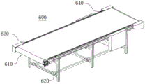
Further, referring to fig. 6, the stamping production integrated equipment further includes a material receiving device 600; the material receiving device comprises a discharge platform 610, and twice the distance between the sheet taking clamp 310 and the sheet taking clamp 320 is matched with the distance between the object platform 110 and the discharge platform 610. Optionally, the aforesaid setting can ensure that the action of sucking the sheet material to be processed and the action of sucking the stamping part are performed simultaneously, thereby ensuring that the stamping part can be placed on the discharging table 610 while the sheet material to be processed is placed on the stamping die.
It should be noted that, when the punching operation is performed, since the sheet taking jig 310 and the punching jig 320 are disposed at an interval, the interval between the two may avoid the punching die, so as to ensure the normal operation of the punching operation.
Besides the arrangement, the second material taking assembly can be set to be in a mode of only conveying to-be-processed sheet materials or stamping parts, and detailed description is omitted.
Referring to fig. 6, the material receiving device 600 further includes a second frame 620; the discharge station 610 employs a belt conveyor assembly including a belt drive element (e.g., a motor), a plurality of belt pulleys pivotally connected to the second frame, and a belt connected to the plurality of belt pulleys; a second sensing element 630 is arranged at the front end of the second frame 620, a third sensing element 640 is arranged at the rear end of the second frame 620, and the second sensing element and the third sensing element are used for sensing whether a stamping part is arranged on the belt or not; the belt driving element, the second sensing element 630 and the third sensing element 640 are all electrically connected with the control device.
Optionally, the second sensing element and the third sensing element may be infrared sensors or photoelectric sensors.
It should be noted that the front end and the rear end of the second frame 620 are relatively speaking, the front end of the second frame 620 is the left end of the second frame 620 shown in fig. 6, and the rear end of the second frame 620 is the right end of the second frame 620 shown in fig. 6.
The second sensing element 630 is used for sensing whether a stamping part is arranged on the belt or not, and controls the conveying stop position of the stamping part through the third sensing element 640, and finally, the stamping part is stacked or conveyed through manual work or other stacking equipment.
Referring to fig. 1, the integrated manufacturing apparatus may further include a punching device 700, wherein the punching device 700 may be installed in the installation position shown in fig. 1.
To further reduce human involvement, the stockpile may be placed on a pallet. Taking the sheet material to be punched to have the magnetic conduction function as an example, referring to fig. 1 to 6, the working process of the production integration equipment is as follows:
manually placing the material pile on the feeding trolley 520 through a forklift;
starting the feeding trolley 520 for feeding to the left side, and stopping the feeding trolley 520 after the feeding trolley 520 runs to a position corresponding to the left-side object stage 110; starting the lifting mechanism 120 to enable the object stage 110 to move upwards and stop after lifting the material pile on the feeding trolley 520;
starting the first material taking assembly 220, the material taking clamp of the first material taking assembly 220 is driven by a material taking power element to move downwards, the material taking clamp of the first material taking assembly 220 sucks the sheet material to be processed under the action of the magnetic sheet separator 240 and sends the sheet material to be processed to the bottom plate 231 of the correcting assembly 230, and the sheet separation sensing element 234 further detects whether the sheet material is single sheet or multiple sheets; if the sheet is a single sheet, starting the positioning driving element to enable the positioning driving element to push the sliding block 233 to move towards the direction close to the fixed block 232 until one side edge of the sheet to be processed is contacted with the fixed block 232; on the contrary, if there are more than one sheets, the sheet-separating sensing element 234 will send a signal to the control device 400, and the control device 400 will stop the operation of the whole apparatus;
starting the material moving device 300, if the material moving device is in the initial use state, the material taking clamp 310 of the material moving device 300 sucks the sheet material to be processed, and the sheet material to be processed is placed on the stamping die of the stamping device 700 under the driving of the transverse driving mechanism 330; if the sheet material is in a continuous use state, the sheet material taking clamp 310 of the material moving device 300 sucks the sheet material to be processed, meanwhile, the sheet material taking clamp 320 sucks the stamping part, the sheet material to be processed is placed on a stamping die of the stamping device 700 by the sheet material taking clamp 310 under the drive of the transverse driving mechanism 330, and meanwhile, the sheet material to be processed is placed on the discharging table 610 by the sheet material taking clamp 320;
at this time, the second sensing element 630 senses that the belt has a stamping part, when the belt moves to the position of the third sensing element 640, the third sensing element 640 sends a signal to the control device 400, and the control device 400 controls the belt to stop running;
when the sheet material to be processed is placed on the discharging table 610, the transverse driving mechanism 330 drives the sheet material taking clamp 310 and the stamping part taking clamp 320 to move in opposite directions, so that the stamping die of the stamping device 700 is located between the sheet material taking clamp 310 and the stamping part taking clamp 320.
Finally, it should be noted that: the above embodiments are only used to illustrate the technical solution of the present invention, and not to limit the same; although the present invention has been described in detail with reference to the foregoing embodiments, it should be understood by those skilled in the art that: the technical solutions described in the foregoing embodiments may still be modified, or some or all of the technical features may be equivalently replaced; such modifications and substitutions do not depart from the spirit and scope of the present invention.
Claims (15)
1. An integrated stamping production apparatus, comprising: the device comprises a material storage device (100), a positioning device (200), a material moving device (300) and a control device (400);
the storing device (100) comprises a loading platform (110) for placing a material pile to be processed;
the positioning device (200) comprises a first rack (210), a first material taking assembly (220) and a correcting assembly (230), wherein the first material taking assembly (220) is movably arranged on the first rack (210), the correcting assembly (230) and the object stage (110) are arranged at intervals along the moving direction of the first material taking assembly (220), the first material taking assembly (220) is used for conveying the sheet stock to be processed on the object stage (110) to the correcting assembly (230), and the correcting assembly (230) is used for positioning the sheet stock to be processed;
the material moving device (300) comprises a second material taking assembly and a material moving driving mechanism in transmission connection with the second material taking assembly, and the second material taking assembly is used for conveying the sheet materials and/or stamping parts to be processed under the driving of the material moving driving mechanism;
the material storage device (100), the positioning device (200) and the material moving device (300) are electrically connected with the control device (400).
2. The integrated press production plant according to claim 1, wherein said magazine (100) further comprises a lifting mechanism (120) and a first inductive element;
the output end of the lifting mechanism (120) is connected with the objective table (110) and used for lifting the objective table (110);
the first sensing element is used for sensing the height position of the top sheet stock of the material pile on the object stage (110), the first sensing element and the lifting mechanism (120) are both electrically connected with the control device (400), and the control device (400) is used for controlling the lifting action of the lifting mechanism (120) and keeping the top sheet stock of the material pile on the object stage (110) at a preset height.
3. The integrated press production plant according to claim 2, further comprising a feeding device (500), the feeding device (500) comprising a rail (510) and a feeding trolley (520) slidably connected to the rail (510);
the feeding trolley (520) comprises a trolley body (521) for placing a material pile to be processed, and a position avoiding hole (5211) for the objective table (110) to pass through is formed in the trolley body (521);
the feeding trolley (520) runs along the track (510) and can be placed above the object stage (110), and the object stage (110) can penetrate through the avoiding hole (5211) under the driving of the lifting mechanism (120) and lift the material stack to be processed on the trolley body (521).
4. The stamping production integration equipment according to claim 3, wherein at least two groups of limiting assemblies are arranged on the vehicle body (521);
each group of limiting assemblies comprises a pressing plate (522) and vertical plates (523), the pressing plate (522) is fixedly arranged on the upper surface of the trolley body (521), the vertical plates (523) are vertically arranged on the pressing plate (522), and at least two vertical plates (523) can limit the position of two side surfaces of a material pile to be processed.
5. The integrated stamping and production plant according to claim 4, wherein the mounting position of the vertical plate (523) on the pressure plate (522) is adjustable for adapting to different sizes of sheets to be processed.
6. The integrated stamping production apparatus according to claim 4, wherein the first inductive element is disposed on the vertical plate (523) of at least one set of the position-limiting assemblies.
7. The stamping production integrated equipment according to claim 3, wherein the storage devices (100) are arranged in two groups, and the two groups of storage devices (100) are arranged at intervals along the extending direction of the track (510);
every group storage device (100) all correspond be provided with pay-off dolly (520), positioner (200) and move material device (300).
8. The stamping production integration apparatus of claim 3, wherein the first frame (210) comprises an upper frame, a lower frame, and a receiving area, the upper frame and the receiving area both being located below the upper frame;
the first material taking assembly (220) is connected to the upper layer rack body in a sliding mode;
the correcting component (230) is arranged on the lower shelf body;
the object stage (110) is arranged in the accommodating area, and a reserved space for enabling the feeding trolley (520) to be erected on the object stage (110) is arranged between the object stage (110) and the upper shelf body.
9. The integrated press production plant according to any one of claims 1 to 8, wherein the first take off assembly (220) is slidably connected to the first frame (210);
the first material taking assembly (220) comprises a material taking power element and a material taking clamp in transmission connection with the material taking power element, and the material taking clamp can be close to or far away from the objective table (110) under the driving of the material taking power element.
10. The integrated stamping production device according to claim 9, wherein the correction assembly (230) comprises a base plate (231), a fixed block (232) arranged on the base plate (231), a sliding block (233) slidably connected to the base plate (231), and a positioning driving element for driving the sliding block (233) to move;
the sliding block (233) can enable the distance between the sliding block (233) and the fixed block (232) to be matched with the size of a sheet to be processed under the driving of the positioning driving element.
11. The integrated stamping and production equipment according to claim 10, wherein a piece sensing element for sensing the number of sheets to be processed is arranged on the base plate (231), and the piece sensing element (234) is electrically connected with the control device (400).
12. The integrated stamping and production apparatus according to claim 9, wherein the positioning device (200) further comprises a magnetic distractor (240), the magnetic distractor (240) being mounted to the first frame (210);
the magnetic separator (240) comprises a magnetic part, wherein the magnetic part is arranged facing the object stage (110) and is used for carrying out magnetic separation on top sheet stocks on the object stage (110).
13. The stamping production integrated equipment according to any one of claims 1 to 8, wherein the second material taking assembly comprises a piece taking clamp (310) and a stamping taking clamp (320), and the piece taking clamp (310) is arranged at a distance from the stamping taking clamp (320);
the material moving driving mechanism comprises a driving transverse driving mechanism (330) and a driving vertical driving mechanism (340), the driving transverse driving mechanism (330) is used for driving the sheet taking material clamp (310) and the sheet taking and stamping part clamp (320) to synchronously move in the horizontal direction, and the driving vertical driving mechanism (340) is used for driving the sheet taking material clamp (310) and the sheet taking and stamping part clamp (320) to synchronously move in the vertical direction;
the movement direction of the sheet taking clamp (310) and the sheet taking and stamping clamp (320) in the horizontal direction is the same as the movement direction of the first taking assembly (220).
14. The integrated press production plant according to claim 13, further comprising a receiving device (600);
the material receiving device (600) comprises a discharging platform (610), and two times of the distance between the sheet taking clamp (310) and the sheet taking and stamping clamp (320) are matched with the distance between the object stage (110) and the discharging platform (610).
15. The integrated stamping and production plant according to claim 14, wherein the receiving device (600) further comprises a second frame (620);
the discharge station (610) adopts a belt type conveying assembly which comprises a belt driving element, a plurality of belt pulleys pivoted to the second rack (620) and a belt connected with the plurality of belt pulleys;
a second sensing element (630) is arranged at the front end of the second rack (620), a third sensing element (640) is arranged at the rear end of the second rack (620), and the second sensing element (630) and the third sensing element (640) are used for sensing whether a stamping part is arranged on the belt or not;
the belt driving element, the second sensing element (630) and the third sensing element (640) are all electrically connected with the control device (400).
Priority Applications (1)
| Application Number | Priority Date | Filing Date | Title |
|---|---|---|---|
| CN202022543483.3U CN213530343U (en) | 2020-11-06 | 2020-11-06 | Stamping production integrated equipment |
Applications Claiming Priority (1)
| Application Number | Priority Date | Filing Date | Title |
|---|---|---|---|
| CN202022543483.3U CN213530343U (en) | 2020-11-06 | 2020-11-06 | Stamping production integrated equipment |
Publications (1)
| Publication Number | Publication Date |
|---|---|
| CN213530343U true CN213530343U (en) | 2021-06-25 |
Family
ID=76480438
Family Applications (1)
| Application Number | Title | Priority Date | Filing Date |
|---|---|---|---|
| CN202022543483.3U Active CN213530343U (en) | 2020-11-06 | 2020-11-06 | Stamping production integrated equipment |
Country Status (1)
| Country | Link |
|---|---|
| CN (1) | CN213530343U (en) |
-
2020
- 2020-11-06 CN CN202022543483.3U patent/CN213530343U/en active Active
Similar Documents
| Publication | Publication Date | Title |
|---|---|---|
| CN208326664U (en) | A kind of automatic emptying machine | |
| CN111229926B (en) | Automatic change fork panel beating production line | |
| CN113955501A (en) | PCB board separates paper board collecting machine | |
| CN212892716U (en) | Single-piece material feeding system | |
| CN211965599U (en) | Automatic change fork panel beating production line | |
| JPH0773765B2 (en) | Multi-collecting small product sorting / collecting device | |
| JP2000044010A (en) | Automatic warehouse system | |
| CN214442352U (en) | Multi-station progressive die material storage and conveying mechanism | |
| CN113320987A (en) | Feeding equipment | |
| CN213530343U (en) | Stamping production integrated equipment | |
| CN110421637B (en) | Battery protection board production equipment | |
| EP3257794B1 (en) | Glass processing table with separate loading and processing areas | |
| CN111151674A (en) | Hydraulic feeding machine | |
| CN216831307U (en) | Punching equipment and punching system | |
| CN112275873A (en) | Stamping production integrated equipment | |
| CN114426190B (en) | Contact placing device | |
| CN111036793A (en) | Double-station sheet metal part feeding mechanism with magnetic force separating function | |
| CN215973643U (en) | Nylon plate feeding mechanism | |
| CN214311798U (en) | Smart card RFID semi-manufactured goods production line | |
| CN213622209U (en) | Buttress material device of breaking a jam | |
| CN212305068U (en) | Stator-rotor notching automatic production device | |
| CN211728147U (en) | Lower electrode plate mounting device of automobile PTC water heater | |
| CN112657866A (en) | Feeding and pressure maintaining integrated assembly line | |
| CN111546031A (en) | Automatic assembling production line for control panel of water heater | |
| CN216795288U (en) | Equipment of circular arc magnet to wireless earphone shell that charges |
Legal Events
| Date | Code | Title | Description |
|---|---|---|---|
| GR01 | Patent grant | ||
| GR01 | Patent grant |